Why Outsource PCB Assembly? 4 Key Benefits

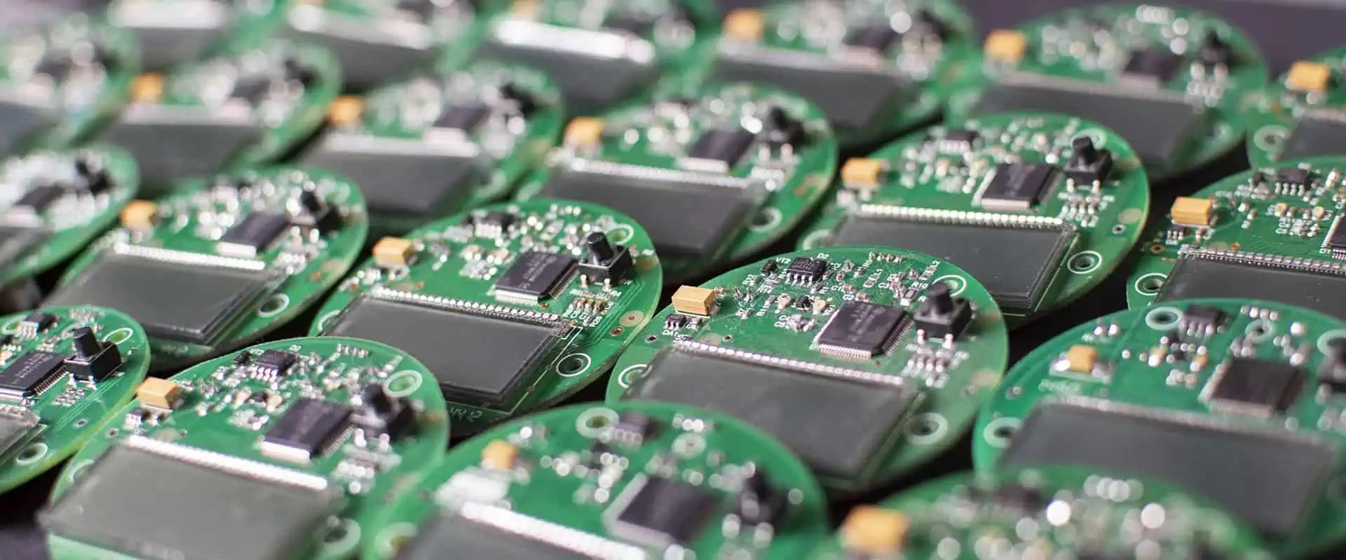
As a procurement professional with over 15 years of experience managing electronics manufacturing partnerships, I’ve seen firsthand how the decision to outsource PCB assembly can make or break a product’s success. Early in my career, I worked for a mid-sized electronics company that insisted on keeping everything in-house. We struggled with quality inconsistencies, astronomical equipment costs, and missed deadlines that frustrated our customers. It wasn’t until we made the strategic shift to outsource our PCB assembly that I truly understood the transformative power of this decision.

Today, I want to share the four key benefits that have consistently proven themselves across multiple industries and countless projects. Whether you’re a startup founder evaluating your first production run or a seasoned engineer reconsidering your manufacturing strategy, understanding these advantages will help you make an informed decision that aligns with your business goals.

Benefit #1: Significant Cost Reduction and Financial Flexibility
Let me be blunt: the financial case for outsourcing PCB assembly is overwhelming. When I first calculated the true cost of in-house assembly for one of my previous employers, the numbers were staggering. We weren’t just paying for the assembly equipment—we were carrying the burden of maintenance contracts, facility costs, insurance, utilities, and a specialized workforce that sat idle during slow periods.

Capital Equipment Investment

The upfront investment required for PCB assembly equipment is substantial. A professional-grade pick-and-place machine alone can cost anywhere from $50,000 to $500,000, depending on its capabilities. Then you need reflow ovens ($20,000-$100,000), solder paste printers ($15,000-$80,000), AOI (Automated Optical Inspection) systems ($30,000-$200,000), and various testing equipment. When I tallied the full equipment list for a modest assembly line, we were looking at an initial investment exceeding $300,000—and that’s before considering the space requirements and infrastructure upgrades.

When you outsource, you eliminate this capital expenditure entirely. Your PCB assembly partner has already made these investments and amortizes them across hundreds of clients. You’re essentially renting access to state-of-the-art equipment without the depreciation headache.

Labor Cost Optimization

One of the most eye-opening revelations in my purchasing career was understanding the true cost of specialized labor. PCB assembly requires trained technicians, quality control specialists, and engineers who understand the intricacies of surface-mount technology, through-hole assembly, and various testing protocols. In my experience, maintaining a full-time assembly team for anything less than continuous high-volume production creates significant inefficiencies.

I remember one particular quarter when our product demand dropped by 40% due to seasonal fluctuations. Our in-house assembly team still needed to be paid, but they had limited work. We tried to find alternative tasks, but the reality was clear: we were paying for capacity we didn’t need. With outsourcing, you only pay for the assemblies you actually produce. This variable cost structure has saved my current company hundreds of thousands of dollars annually.

Reduced Overhead and Hidden Costs

Beyond the obvious expenses, in-house assembly carries numerous hidden costs that often surprise decision-makers. Climate-controlled environments for component storage, ESD-safe workstations, regular equipment calibration, consumables like solder paste and flux, waste disposal for hazardous materials, and compliance with environmental regulations all add up quickly.

In one memorable instance, our facility failed an environmental audit because our solder waste disposal procedures weren’t up to code. The corrective actions cost us $30,000 and three weeks of production downtime. A reputable PCB assembly partner already has these systems in place and the expertise to maintain compliance.

Benefit #2: Access to Advanced Technology and Expertise

The pace of technological advancement in PCB assembly is relentless. New component packages, assembly techniques, and quality control methods emerge constantly. Keeping pace with these developments while managing your core business operations is nearly impossible.

Cutting-Edge Equipment and Processes

Professional PCB assembly services invest continuously in the latest technology because it’s their core business. Last year, I worked with a contract manufacturer that had just installed a new high-speed pick-and-place machine capable of placing 80,000 components per hour with 99.99% accuracy. This machine cost over $600,000. For our project volume, purchasing this equipment ourselves would have taken 15 years to justify financially—by which time it would be obsolete.

These partners also maintain expertise across various assembly technologies. Whether you need traditional through-hole assembly, advanced surface-mount technology, ball grid array (BGA) placement, or chip-on-board assembly, experienced providers have the right equipment and trained personnel. When we developed a product requiring 0201 components (incredibly tiny surface-mount devices measuring just 0.6mm x 0.3mm), our outsourcing partner handled it without hesitation. Attempting this in-house would have required new equipment and months of training.

Specialized Knowledge and Problem-Solving

One of the most valuable aspects of outsourcing is tapping into your partner’s accumulated knowledge. Experienced PCB assembly providers have seen thousands of designs and encountered virtually every assembly challenge imaginable. They can identify potential manufacturing issues during design review and suggest modifications that improve yield and reduce costs.

I recall a project where our engineering team designed a board with components placed too close together for automated assembly. Our assembly partner caught this during the DFM (Design for Manufacturing) review and suggested minor layout changes that prevented what would have been a 30% yield loss. Their expertise saved us from a costly mistake that our in-house team, despite their competence in design, simply didn’t have the assembly experience to foresee.

Quality Systems and Certifications

Reputable PCB assembly services maintain rigorous quality management systems and industry certifications that would be prohibitively expensive for most companies to achieve independently. ISO 9001, ISO 13485 (for medical devices), AS9100 (for aerospace), IATF 16949 (for automotive), and IPC certifications demonstrate a commitment to quality that provides peace of mind.

During my tenure in the medical device industry, we needed ISO 13485 certification for our assembly processes. Achieving this certification in-house would have required an 18-month effort, extensive documentation, facility upgrades, and annual audits. Our outsourcing partner already maintained this certification, allowing us to leverage their compliance framework and bring our product to market 12 months faster.

Benefit #3: Accelerated Time-to-Market and Scalability

In today’s competitive landscape, time-to-market can determine whether a product succeeds or fails. Outsourcing PCB assembly provides flexibility and speed that in-house operations struggle to match.

Rapid Production Ramp-Up

When you need to go from prototype to production, the timeline matters enormously. Setting up an in-house assembly line, even a modest one, typically requires 6-12 months when you factor in equipment procurement, facility preparation, staff hiring and training, and process validation. I’ve worked with PCB assembly partners who can transition from prototype to full production in as little as 2-4 weeks.

This speed proved critical for one of my most memorable projects—a consumer electronics product launching during the holiday season. Our original timeline had us starting production in May for October delivery. Due to design revisions, we didn’t finalize the product until July. An outsourcing partner with available capacity and experience in similar products helped us compress the production timeline, ultimately delivering on schedule. Attempting this in-house would have been impossible.

Flexible Scaling for Business Growth

Business demands fluctuate, and production capacity must adapt accordingly. With in-house assembly, you’re forced to choose between maintaining excess capacity (wasting resources during slow periods) or insufficient capacity (losing sales opportunities during peaks). Outsourcing elegantly solves this dilemma.

I currently manage electronics procurement for a company experiencing 200% year-over-year growth. Our PCB assembly partner has scaled with us seamlessly, from producing 1,000 units monthly in our first year to over 20,000 units today. They’ve allocated additional production lines, adjusted scheduling, and maintained consistent quality throughout this growth. Building this capacity internally would have required millions in investment and carried enormous risk if our growth trajectory changed.

Focus on Core Competencies

Perhaps the most strategic benefit of outsourcing is allowing your organization to focus on what it does best. Unless PCB assembly is your core business, managing it internally diverts attention and resources from activities that truly differentiate your company.

In my experience, the most successful electronics companies excel at product design, customer relationships, market positioning, or innovative features—not necessarily manufacturing. When we outsourced assembly, our engineering team stopped spending 30% of their time on manufacturing issues and redirected that effort toward next-generation product development. This focus accelerated our innovation cycle and strengthened our competitive position.

Benefit #4: Enhanced Risk Management and Quality Assurance

Manufacturing carries inherent risks—quality defects, supply chain disruptions, regulatory compliance, and technological obsolescence. Experienced PCB assembly partners help mitigate these risks through established systems and industry expertise.

Comprehensive Quality Control

Professional assembly services implement multi-stage quality control processes that catch defects early and prevent costly failures. These typically include incoming component inspection, solder paste inspection (SPI), automated optical inspection (AOI) after placement and reflow, X-ray inspection for hidden connections, in-circuit testing (ICT), and functional testing.

I learned the value of thorough quality control the hard way. Early in my career, working with a company doing in-house assembly, we shipped a batch of 500 units with a placement error that caused intermittent failures. The warranty claims, replacement costs, and damaged reputation cost us dearly. Since outsourcing to partners with comprehensive QC systems, our field failure rate has dropped by 85%.

Supply Chain Management and Component Procurement

PCB assembly requires procuring dozens or hundreds of different components from various suppliers. Managing these relationships, ensuring component authenticity, maintaining appropriate inventory levels, and navigating supply chain disruptions demands significant expertise and buying power.

Established assembly partners maintain relationships with authorized distributors and component manufacturers, providing access to better pricing and allocation during shortages. During the recent global chip shortage, our assembly partner’s established relationships and inventory management helped us maintain production while competitors faced months-long delays. Their purchasing power and expertise in component substitution proved invaluable.

Reduced Liability and Compliance Burden

Manufacturing carries legal responsibilities related to worker safety, environmental compliance, and product liability. Outsourcing transfers many of these risks to your assembly partner, who has specialized expertise in managing them.

This doesn’t mean you’re completely insulated from liability—you’re still responsible for your product’s design and performance. However, manufacturing-related issues like workplace accidents, environmental violations, or process-related defects become the assembly partner’s responsibility. The insurance requirements alone for manufacturing operations can be substantial; leveraging your partner’s coverage reduces your risk exposure.

Making the Outsourcing Decision: Practical Considerations

After outlining these four key benefits, I want to share some practical guidance for actually making the outsourcing decision and selecting the right partner.

When Does Outsourcing Make Sense?

Based on my experience, outsourcing PCB assembly typically makes strong sense when:

  • Your annual production volume is under 100,000 units (above this, in-house may be economical)
  • Your product design changes frequently, requiring assembly process flexibility
  • You lack specialized assembly expertise in-house
  • Capital is limited or better deployed elsewhere in your business
  • You need to scale production quickly to meet market demands
  • Your products require industry certifications you don’t currently maintain

Selecting the Right Assembly Partner

Not all PCB assembly services are equal. I evaluate potential partners using these criteria:

Technical Capabilities: Ensure they can handle your component types, board complexity, and volume requirements. Request capability statements and tour their facilities if possible.

Quality Systems: Verify appropriate certifications for your industry. Ask about defect rates, quality control processes, and how they handle non-conformances.

Communication: Responsive, clear communication is essential. During the vetting process, assess how quickly they respond and how well they understand your requirements.

Financial Stability: You’re entering a long-term partnership. Review their business history and financial health to ensure they’ll be around for your product’s lifecycle.

References and Reputation: Speak with current customers about their experiences. Online reviews provide some insight, but direct conversations reveal more.

Pricing Structure: Understand all costs including setup fees, component procurement markups, testing charges, and shipping. The lowest quote isn’t always the best value.

Conclusion: Strategic Advantage Through Smart Outsourcing

After years of managing electronics procurement and working with dozens of PCB assembly partners, I’m convinced that outsourcing is not just a cost-cutting measure—it’s a strategic advantage that enables companies to compete more effectively in today’s fast-paced market.

The four benefits I’ve outlined—cost reduction, access to advanced technology, accelerated time-to-market, and enhanced risk management—compound over time. The money you save on equipment and overhead can fund product development. The expertise you gain access to improves your designs. The time you save accelerates your innovation cycle. The risks you mitigate protect your business reputation.

That said, successful outsourcing requires finding the right partner and managing the relationship actively. Treat your PCB assembly service as a strategic partner, not just a vendor. Share your roadmap, communicate openly about challenges, and work collaboratively to optimize processes and costs.

Whether you’re producing your first prototype or scaling to meet explosive growth, the right PCB assembly partner can be the difference between struggling with manufacturing challenges and focusing on what truly drives your business forward. In my experience, that focus—on innovation, customers, and market opportunities—is what ultimately determines success in the competitive electronics industry.

Understanding Controlled Impedance in PCB Design: A Complete Guide

impedance control pcb

In modern electronics, controlled impedance has become a critical consideration for PCB designers working with high-speed digital circuits. As signal frequencies increase and rise times decrease, understanding and implementing controlled impedance becomes essential for maintaining signal integrity and ensuring reliable circuit performance.

This comprehensive guide explores everything you need to know about controlled impedance in PCB design, from fundamental concepts to practical implementation strategies.

YouTube video

What is Controlled Impedance?

Controlled impedance refers to the characteristic impedance of a transmission line on a printed circuit board that has been designed and manufactured to meet specific impedance requirements. Unlike standard PCB traces, controlled impedance traces have precise geometric and material specifications that determine their electrical properties.

The characteristic impedance of a transmission line represents the ratio of voltage to current for a signal propagating along that line. In PCB design, this impedance must be carefully controlled to prevent signal reflections, maintain signal quality, and ensure proper communication between components.

When a signal travels through a PCB trace, it encounters the trace’s impedance. If this impedance matches the source and load impedances, the signal transmits efficiently. However, impedance mismatches cause signal reflections, leading to data errors, electromagnetic interference, and circuit malfunction.

Why Controlled Impedance Matters in Modern PCB Design

The importance of controlled impedance has grown exponentially with advancing technology. High-speed digital interfaces like USB, HDMI, PCIe, DDR memory, and Ethernet all require precise impedance control for reliable operation.

Several factors make controlled impedance critical:

Signal Integrity: Impedance mismatches cause reflections that distort signal waveforms. These distortions can result in timing errors, increased jitter, and reduced noise margins. Controlled impedance ensures clean signal transmission.

EMI Reduction: Proper impedance matching minimizes electromagnetic interference. When impedance is controlled, signals propagate smoothly without generating excessive radiated emissions that could interfere with other circuits or violate regulatory standards.

Power Efficiency: Impedance mismatches waste power through reflections. Controlled impedance maximizes power transfer from source to load, improving overall system efficiency.

Design Reliability: Modern communication protocols specify impedance tolerances. Meeting these specifications ensures compatibility and reliable operation across different devices and manufacturers.

Key Factors Affecting Controlled Impedance

Multiple parameters influence the impedance of PCB traces. Understanding these factors helps designers create accurate controlled impedance structures.

Trace Geometry

The physical dimensions of the trace significantly impact impedance. Trace width, thickness, and length all contribute to the overall impedance value. Wider traces generally have lower impedance, while narrower traces have higher impedance.

The relationship between trace width and impedance is not linear. Small changes in trace width can produce significant impedance variations, especially with narrower traces. This makes precise manufacturing control essential.

Dielectric Material Properties

The PCB substrate material plays a crucial role in determining controlled impedance. The dielectric constant (Dk or εr) of the PCB material affects how electromagnetic fields propagate through the board.

Common FR-4 materials have dielectric constants ranging from 3.8 to 4.8, depending on resin content and glass weave. High-performance applications often use specialized materials like Rogers or Isola substrates with tighter Dk tolerances and lower loss characteristics.

The dielectric thickness between the signal trace and reference plane directly affects impedance. Thicker dielectrics increase impedance, while thinner dielectrics decrease it. Manufacturers must maintain tight thickness tolerances to achieve controlled impedance.

Reference Planes

Ground and power planes serve as reference planes for controlled impedance traces. The distance between the signal trace and its reference plane is critical for impedance calculation.

Microstrip traces have a reference plane on one side, while stripline traces have reference planes on both sides. The configuration choice depends on the specific impedance requirements and board stack-up design.

Copper Weight

The thickness of copper used in PCB traces affects impedance, though less dramatically than trace width or dielectric thickness. Standard copper weights include 0.5 oz, 1 oz, and 2 oz per square foot.

Heavier copper provides better current-carrying capacity but can complicate controlled impedance design. The manufacturing process also affects final copper thickness through plating processes.

Calculating Controlled Impedance

Designers use several methods to calculate controlled impedance values. The complexity of these calculations depends on the trace geometry and board stack-up.

Microstrip Impedance

Microstrip traces run on the outer layers of a PCB with a reference plane below. The basic formula for microstrip impedance considers trace width, trace height, dielectric thickness, and dielectric constant.

Field solver software provides accurate impedance calculations by solving Maxwell’s equations numerically. These tools account for complex geometries and material variations that analytical formulas cannot handle precisely.

Stripline Impedance

Stripline traces exist between two reference planes within the PCB stack-up. This configuration provides better electromagnetic shielding and more symmetrical field distribution compared to microstrip.

Stripline impedance calculations require knowing the distances to both reference planes and the dielectric properties of surrounding materials. Asymmetric stripline designs, where the trace is not centered between planes, require more complex calculations.

Differential Impedance

Differential signaling uses two traces carrying complementary signals. The differential impedance depends not only on single-ended impedance but also on coupling between the trace pair.

Differential impedance calculations must account for trace spacing, as closer spacing increases coupling and reduces differential impedance. Many high-speed interfaces specify both single-ended and differential impedance requirements.

Common Controlled Impedance Values

Industry standards specify particular impedance values for different applications. Understanding these standard values helps designers make appropriate choices.

50 Ohms: This is the most common single-ended impedance specification. RF applications, antenna connections, and many high-speed digital interfaces use 50-ohm impedance. This value provides a good balance between power handling and signal loss.

75 Ohms: Video applications and cable television systems typically use 75-ohm impedance. This higher impedance reduces cable loss for video signals.

85-100 Ohms: Differential pairs often target this impedance range. USB specifies 90 ohms differential, while HDMI requires 100 ohms differential impedance.

PCIe and SATA: These high-speed serial interfaces require 85-ohm differential impedance with tight tolerances, typically ±10%.

DDR Memory: Memory interfaces commonly use 40-50 ohm single-ended impedance, with specific values depending on the DDR generation and implementation.

Design Considerations for Controlled Impedance

Successfully implementing controlled impedance requires careful attention throughout the design process.

Stack-up Planning

The PCB stack-up fundamentally determines controlled impedance capabilities. Designers must work closely with manufacturers to develop stack-ups that meet impedance requirements while considering manufacturing capabilities and cost constraints.

A well-designed stack-up places signal layers adjacent to reference planes with appropriate dielectric thicknesses. This arrangement provides controlled impedance while maintaining signal integrity.

Trace Routing

Maintaining consistent trace geometry throughout the routing is essential. Width variations, voids in reference planes, and routing near board edges can all disrupt controlled impedance.

Designers should avoid routing controlled impedance traces across gaps in reference planes. When plane crossings are unavoidable, stitching capacitors help maintain a continuous return path.

Length Matching

Many high-speed interfaces require matched trace lengths in addition to controlled impedance. Differential pairs must maintain tight length matching to prevent skew. DDR memory interfaces require length matching across multiple signal groups.

Serpentine routing patterns can adjust trace lengths, but designers must ensure these patterns maintain proper spacing and impedance control.

Documentation

Clear documentation communicates impedance requirements to manufacturers. Fabrication drawings should specify target impedance values, tolerances, and which traces require impedance control.

Many designers create impedance tables that list all controlled impedance requirements with their associated net names or net classes. This documentation helps prevent manufacturing errors.

Testing and Verification

Verifying controlled impedance ensures manufactured boards meet design specifications.

Time Domain Reflectometry (TDR)

TDR testing sends fast-rise-time pulses down traces and measures reflections. The reflection pattern reveals impedance discontinuities and allows precise impedance measurement along the trace length.

TDR testing can identify specific problem areas, such as via transitions, connector interfaces, or manufacturing defects. This detailed information helps debug impedance issues.

Coupon Testing

Manufacturers often include test coupons on PCB panels specifically for impedance verification. These coupons contain representative controlled impedance structures that can be tested without damaging production boards.

Coupon testing provides statistical confidence that the manufacturing process achieves target impedance values across the entire production run.

Common Controlled Impedance Challenges

Even experienced designers encounter challenges when implementing controlled impedance.

Manufacturing Variation

PCB manufacturing processes have inherent variations. Copper thickness, dielectric thickness, and dielectric constant can all vary within specified tolerances. These variations affect final impedance values.

Designers must account for manufacturing tolerances when specifying controlled impedance. Working with the fabricator to understand their process capabilities helps set realistic expectations.

Via Transitions

Vias create impedance discontinuities because their geometry differs from trace geometry. The capacitance and inductance of vias can cause reflections at high frequencies.

Designers minimize via impacts by using smaller via diameters, back-drilling unused via stubs, and optimizing via pad sizes. Some designs use ground vias adjacent to signal vias to improve impedance matching.

Component Interfaces

Connecting controlled impedance traces to component pads often creates impedance discontinuities. The pad geometry differs from the trace geometry, causing localized impedance changes.

Careful pad design and trace tapering can minimize these discontinuities. Some designs use impedance-matching networks or termination components to compensate for unavoidable mismatches.

Conclusion

Controlled impedance represents a fundamental aspect of modern PCB design. As signal speeds increase and digital interfaces evolve, understanding and implementing proper impedance control becomes increasingly critical for design success.

By carefully considering trace geometry, material properties, stack-up design, and manufacturing capabilities, designers can create robust controlled impedance structures that ensure signal integrity and reliable circuit operation. The investment in proper controlled impedance design pays dividends through improved performance, reduced EMI, and fewer design iterations.

Whether you’re designing simple 50-ohm RF connections or complex differential pairs for high-speed digital interfaces, mastering controlled impedance principles enables you to create professional, reliable PCB designs that meet modern performance requirements.

The Essential Role of Prototyping in Circuit Board Development

Introduction

Prototyping is the backbone of successful circuit board development. It bridges the gap between your initial design concept and full-scale production. This critical phase allows you to test, validate, and refine your PCB designs before investing in expensive manufacturing runs.

Modern electronics development has made prototyping more accessible than ever. However, this accessibility has also made it more essential. Today’s compressed development timelines and complex circuit requirements mean that skipping the prototype phase is simply not an option.

In this article, we’ll explore why prototyping plays such a vital role in circuit board development. You’ll discover how it saves time, reduces costs, and ultimately leads to better products.

YouTube video

Why Design Validation Matters

Testing Theory Against Reality

Your PCB design software is powerful, but it can’t predict everything. Schematic capture tools and simulators have limitations. Real-world factors like parasitic capacitance, electromagnetic interference, and thermal behavior often surprise even experienced engineers.

Prototyping lets you test your designs under actual operating conditions. You can verify that components mount correctly and solder joints form properly. More importantly, you can confirm that your board performs as expected across its full temperature range.

Measuring What Matters

For high-frequency designs, prototypes are absolutely essential. You need to measure real signal integrity, not just simulate it. Parameters like rise times, crosstalk, and impedance matching can make or break your design.

Additionally, prototypes reveal your actual power consumption. They show you thermal hotspots through infrared imaging. They prove whether your board fits properly in its enclosure. This empirical data is invaluable for optimization.

Catching Problems Early Saves Money

The Cost of Late Detection

Here’s a simple truth: finding errors early costs far less than fixing them later. A design flaw caught during prototyping might cost a few hundred dollars to correct. The same flaw discovered after manufacturing 10,000 units could cost hundreds of thousands.

This economic principle drives the entire prototyping philosophy. Early detection prevents catastrophic losses.

Common Issues Prototypes Reveal

Prototyping uncovers problems that drawings can’t show you. These include:

  • Incorrect component footprints
  • Inadequate trace widths for current requirements
  • Insufficient clearance in high-voltage sections
  • Poor ground plane implementation
  • Component incompatibilities

Moreover, subtle issues often emerge during testing. Power supply noise might couple into analog circuits. Decoupling capacitors might be poorly placed. Feedback loops might oscillate unexpectedly. You’ll catch these problems with a prototype in hand.

Beyond Electrical Issues

Mechanical and assembly problems also surface during prototyping. Component placement that looks good on screen might create assembly nightmares. Connectors might face the wrong direction for cable routing. Test points might become inaccessible after board mounting.

These practical considerations emerge naturally during prototype work. Consequently, you can fix them before production tooling is finalized.

The Power of Iterative Development

Building Better Designs Step by Step

Modern circuit development follows an iterative process. Each prototype generation incorporates lessons from the previous version. This approach lets you experiment without the financial burden of large production runs.

Your first prototype typically proves basic functionality. It answers the question: “Does the core concept work?” Your second prototype might optimize performance or reduce costs through component substitution. The third often represents your pre-production unit.

Faster Development Through Parallel Work

This iterative methodology accelerates development timelines. While you analyze one prototype revision, the next can be in fabrication. Therefore, you maintain momentum throughout the development cycle.

Furthermore, rapid prototyping services now offer turnaround times measured in days. This enables multiple iteration cycles within tight schedules.

Aligning with Agile Practices

Iterative prototyping aligns perfectly with agile development. You can respond quickly to changing requirements or new discoveries. This flexibility is crucial in today’s fast-moving electronics market.

Managing Risk with New Technologies

Validating Unfamiliar Territory

New technologies always carry risk. Whether you’re working with HDI designs, embedded components, or advanced materials like Rogers laminates, unknowns abound. Prototyping helps you manage these risks effectively.

Through hands-on prototype work, you gain practical experience with unfamiliar processes. You validate vendor capabilities. You assess whether new technologies deliver their promised benefits.

Making Informed Technology Decisions

For example, consider switching from FR-4 to Rogers material for RF applications. The theory suggests performance improvements. However, prototyping confirms whether the enhanced electrical properties justify the increased costs.

Similarly, when qualifying new component suppliers, prototypes enable thorough validation. This is especially important for semiconductors where subtle manufacturing differences affect circuit behavior.

Bridging Design and Manufacturing

Understanding DFM Considerations

Prototyping connects design engineering with manufacturing realities. Design-for-manufacturability (DFM) issues surface before production begins. This connection is invaluable.

While prototype shops often accommodate aggressive designs, production facilities impose tighter constraints. These constraints optimize yield and control costs.

Key Manufacturing Parameters

Several factors impact manufacturability:

Prototype fabrication provides tangible feedback on these parameters. Consequently, you can adjust specifications for optimal production outcomes.

Optimizing for Automated Assembly

The prototype assembly process reveals considerations for automation. Component orientation affects pick-and-place efficiency. Adequate fiducial marks enable machine vision systems. Proper paste stencil apertures ensure consistent solder application.

Working with prototype assemblies allows manufacturing engineers to refine processes early. This reduces startup time and scrap rates during production launch.

Developing Robust Testing Procedures

Building Your Test Strategy

Prototypes provide the foundation for comprehensive test procedures. You’ll use them throughout production to ensure quality. Therefore, investing time in test development during prototyping pays long-term dividends.

Engineers use prototypes to establish functional test parameters. They define acceptable performance ranges. They develop automated test equipment (ATE) programs.

Validating Test Coverage

In-circuit testing (ICT) and flying probe strategies can be developed using prototypes. This ensures adequate defect detection without false failures. Similarly, boundary scan testing (JTAG) implementations can be validated.

Additionally, firmware loading procedures can be refined using prototype hardware.

Meeting Regulatory Requirements

For products requiring regulatory compliance, prototypes serve as test samples. This includes FCC certification, CE marking, and UL safety certification. Successfully passing compliance testing with prototypes provides confidence for production units.

This approach avoids costly delays from failed certification attempts.

Creating Valuable Documentation

Building Your Knowledge Base

The prototyping phase generates documentation that supports your entire product lifecycle. Test results, measurement data, and thermal studies all contribute to comprehensive product records.

This empirical data supplements theoretical calculations. It provides evidence-based specifications for component tolerances and operating conditions.

Supporting Long-Term Success

When questions arise during production or field deployment, prototype data offers authoritative reference information. This supports troubleshooting and problem resolution.

Furthermore, prototype evaluation often reveals documentation improvements needed. You might clarify ambiguous specifications, add missing dimensions, or highlight critical assembly requirements.

These refinements prevent miscommunication during production scaling.

Making the Investment Pay Off

Understanding the ROI

Circuit board prototyping represents a necessary investment, not an optional expense. The returns come through reduced development risk and accelerated time-to-market. You’ll also achieve optimized product performance and minimized production costs.

Organizations that skip prototyping inevitably face greater difficulties during production launch. Problems that could have been resolved for hundreds of dollars end up costing thousands.

Future-Proofing Your Development

As electronics continue advancing in complexity, prototyping becomes even more critical. Higher frequencies, denser component packaging, and mixed-signal integration all demand thorough validation.

Engineers who embrace iterative development through effective prototyping position themselves for success. They deliver better products faster and more reliably.

Conclusion

Prototyping is not just a preliminary step in electronics development. It’s an essential methodology for transforming concepts into manufacturable, reliable products. The empirical validation it provides cannot be replicated through simulation alone.

The investment in prototyping delivers measurable returns. You’ll reduce development risk and accelerate time-to-market. Your products will perform better and cost less to manufacture.

Therefore, view prototyping as a competitive advantage. Organizations that embrace this approach consistently outperform those that don’t. In today’s complex electronics marketplace, prototyping isn’t optional—it’s essential for success.


Frequently Asked Questions

How many prototype iterations do I need before production?

The number of iterations varies based on your design complexity. Simple designs with proven technology might need only one or two cycles. Complex, innovative designs might require four to six iterations.

Most projects benefit from at least two iterations. First, create a functional prototype to validate core concepts. Second, build a pre-production prototype that incorporates refinements.

Several factors influence iteration count. These include design novelty, team experience, and market timing constraints. However, rushing through prototyping to save time usually backfires.

What’s different between prototype and production PCB fabrication?

Prototype fabrication offers faster turnaround times and accepts more aggressive design rules. Prototype houses maintain diverse material inventory and flexible manufacturing processes. They can accommodate smaller quantities economically.

Production fabrication emphasizes cost optimization and yield maximization. Production facilities may impose more conservative design rules to ensure high yields. They typically require minimum order quantities that make small runs impractical.

Additionally, production involves more rigorous process controls. This includes extensive documentation and quality certifications required for commercial products.

Does rapid prototyping really save time and money?

Yes, rapid prototyping dramatically compresses development timelines. Services offering 24-hour to 5-day turnaround enable faster design iteration. You can evaluate multiple approaches within timeframes that previously allowed only single iterations.

While rapid prototyping costs more per board, overall program costs often decrease. You’ll spend less engineering time and resolve problems faster. Earlier market entry typically justifies the premium.

Furthermore, quick validation prevents costly delays during production ramp-up. Schedule impacts during production typically far exceed prototype fabrication costs.

What testing should I perform on prototype boards?

Start with visual inspection for manufacturing defects. Then perform continuity testing to verify correct connectivity. Power-on testing ensures no shorts or excessive current draw.

Next, conduct functional testing of all circuit blocks. Additional testing might include:

  • Performance characterization against specifications
  • Environmental testing (temperature cycling, humidity)
  • Signal integrity analysis for high-speed designs
  • EMI/EMC pre-compliance testing
  • Thermal analysis under worst-case conditions

Your specific test regimen depends on your application. However, the goal remains constant: thoroughly validate all design aspects before production.

Can I use prototypes for FCC or UL certification testing?

Yes, prototypes are commonly used for regulatory compliance testing. Submitting prototypes for certification is standard practice. It allows you to address compliance issues before production begins.

However, your prototypes must represent the production design accurately. Significant changes after certification might require retesting. Some certifications distinguish between prototype and production testing.

Consult certification bodies early in development. This ensures your prototypes are suitable for compliance testing. You’ll also need documentation proving equivalence between tested prototypes and production units.

How do I choose the right prototyping service provider?

Evaluate multiple factors beyond just cost. Key considerations include turnaround time capabilities and technical capabilities. Check their layer count limits, minimum feature sizes, and material options.

Review their design rule specifications carefully. Ensure they support your requirements without forcing unnecessary compromises. Consider whether they offer assembly services if you need populated boards.

Examine their quality certifications, including IPC standards compliance and ISO certifications. Check their responsiveness to technical questions. For critical projects, consider ordering samples from multiple vendors for comparison.

Establishing relationships with both rapid and standard-turnaround providers offers flexibility. This serves different project phases and budget constraints effectively.

Planning a PCB Design? 5 Critical Things to Consider First

Hey there! I’m a 15-year-old PCB designer, and yeah, I know that sounds kind of wild, but designing circuit boards has been my obsession for the past couple of years. When I first started, I jumped straight into designing without really planning things out, and let me tell you – that was a huge mistake. I’ve learned the hard way that proper planning can save you tons of time, money, and frustration. So, let me share the five most critical things you need to consider before you even open your PCB design software.

YouTube video

1. Understanding Your Circuit Requirements and Specifications

Okay, so this might sound super obvious, but you’d be surprised how many people (including past me) skip this step. Before you start placing components and routing traces, you need to have a crystal-clear understanding of what your circuit actually needs to do.

When I designed my first Arduino-based weather station, I thought I had everything figured out. Spoiler alert: I didn’t. I forgot to consider the power requirements properly, and my battery drained way faster than expected. That’s when I learned that planning starts with asking the right questions.

What you need to figure out:

First, determine your power requirements. How much current will your circuit draw? What voltage do you need? Will it run on batteries or a wall adapter? These questions matter because they affect everything from trace width to component selection. I made a spreadsheet now where I list every component and its power consumption – it’s a game-changer.

Second, think about the signals you’re working with. Are you dealing with high-speed digital signals, analog signals, or a mix of both? This is crucial because high-speed signals need special attention to avoid interference and signal integrity issues. When I built my first radio receiver circuit, I didn’t separate my analog and digital grounds properly, and the noise was insane. Learning about proper grounding took my designs from “kind of works” to “actually reliable.”

Third, consider the operating environment. Is your PCB going to be in a hot environment? Will it be exposed to moisture? These factors determine what materials you should use and whether you need conformal coating. My robot project taught me this lesson when moisture got into the board during a rainy day test run – not fun.

2. Component Selection and Availability

This is probably where I’ve made the most mistakes, and honestly, it’s still something I’m learning to get better at. Choosing the right components is like picking the right ingredients for a recipe – you can’t make a great dish with ingredients you can’t find or afford.

The availability trap:

Here’s something I wish someone had told me earlier: just because a component exists doesn’t mean you can actually get it. I once designed an entire board around this super cool microcontroller I found online, only to discover it was out of stock everywhere and wouldn’t be available for six months. That was painful.

Now, before I commit to any component, I check at least three different suppliers (like Mouser, Digikey, and LCSC) to see if it’s actually in stock and what the lead times are. I also look for multiple sources – if only one company makes the part you need, that’s a red flag. Trust me, having backup options for critical components can save your project.

Package selection matters more than you think:

When I started, I always picked the smallest packages because they looked cool and professional. SMD components smaller than 0603 seemed so high-tech! But here’s the reality: if you’re hand-soldering (which I am, at least for prototypes), going too small makes your life miserable. I now stick to 0805 or 1206 packages for passives when I’m prototyping. Yes, it makes the board slightly bigger, but I can actually solder it without a microscope.

Also, think about whether you’ll need to replace components later. Through-hole parts are way easier to swap out than surface-mount ones. For critical components that might fail or that you’re experimenting with, through-hole can be your friend.

Cost considerations:

As a teenager working on projects with birthday money and the occasional odd job, budget is real for me. I learned to use parametric searches on supplier websites to find components that meet my specs at the best price. Sometimes a slightly different capacitor value or resistor tolerance can save you significant money when you’re ordering in bulk.

3. PCB Layout Considerations: Layers, Size, and Traces

This is where the magic happens, but also where things can go really wrong if you don’t plan ahead. The physical layout of your PCB isn’t just about making components fit – it’s about making them work together properly.

How many layers do you actually need?

My first few boards were all two-layer designs because I thought more layers meant it was too complicated for me. Wrong mindset! The number of layers you need depends on your circuit complexity, signal integrity requirements, and power distribution needs.

For simple projects like LED controllers or basic Arduino shields, two layers work great. But when I started working with higher-speed circuits and needed proper power and ground planes, I discovered that four-layer boards aren’t as scary or expensive as I thought. The manufacturers I use charge like $5-10 extra for four layers, which is totally worth it for the improved performance and easier routing.

Ground and power planes are your friends. They reduce noise, provide better current distribution, and make routing so much easier. Once I started using dedicated power planes, my circuits became way more stable.

Size matters (but maybe not how you think):

I used to try to make my boards as small as physically possible because it seemed more impressive. But here’s what I learned: unless you have a specific size requirement (like fitting in an enclosure), giving yourself a bit of extra space makes everything easier.

Extra space means:

  • Easier hand soldering
  • Room for test points (which you definitely want)
  • Space for mounting holes
  • Better thermal management
  • Easier troubleshooting

Now I design for functionality first and only optimize for size if I actually need to. My boards might be 20% bigger than they could be, but they’re 100% easier to work with.

Trace width and spacing:

This is pure physics, and you can’t cheat it. The amount of current a trace can carry depends on its width and the copper thickness. I use an online trace width calculator for every power trace now. After I had a trace literally burn up on one of my first boards (scary!), I learned to always oversize power traces.

For signal traces, keep them as short as possible, especially for high-speed signals. I learned about impedance-controlled routing the hard way when my USB project wouldn’t work reliably. Differential pairs like USB need to be routed together with matched lengths – the design software can help with this, but you need to plan for it from the start.

4. Manufacturing Capabilities and Constraints

Here’s something nobody tells beginners: not every design you create can actually be manufactured, at least not affordably. Different PCB manufacturers have different capabilities, and understanding these limitations before you design can save you from costly redesigns.

Know your manufacturer’s rules:

Every PCB fab house has design rules – minimum trace width, minimum spacing, minimum drill size, etc. Most affordable manufacturers can handle 6mil traces and spaces, but if you go smaller, the price jumps up fast. I always download the design rules from my intended manufacturer and load them into my PCB software before I start routing.

When I designed my first board, I used 4mil traces in some places because the software let me. Then I got a quote that was three times what I expected because those tiny traces required a more expensive manufacturing process. Now I design to standard capabilities (6mil minimum) unless I absolutely need smaller features.

Surface finish and special features:

You’ve got options like HASL, ENIG, or immersion silver for surface finish. For my projects, I usually use HASL (Hot Air Solder Leveling) because it’s the cheapest and works fine for hand soldering. But if you’re doing fine-pitch SMD work or want better shelf life, ENIG is worth considering – it just costs more.

Some other things to think about:

  • Do you need a soldermask color other than green? (It costs extra, but red and black look cool)
  • Silkscreen on both sides? (Usually free, but plan for it)
  • Edge plating or castellated holes? (Cool but specialty)
  • Controlled impedance? (Need to specify this upfront)

Panel vs. single board:

Most manufacturers have a minimum order quantity, usually 5-10 boards. But here’s a trick I learned: if you have multiple small designs, you can panelize them together into one order. I’ve put two or three different projects on one panel and just snap them apart when they arrive. This saves money when you’re experimenting with multiple ideas.

5. Testing and Prototyping Planning

This is the part that nobody really talks about but is super important. Your first board probably won’t work perfectly – that’s just reality. Planning for testing and debugging from the beginning makes your life so much easier.

Build in test points:

I add test points everywhere now – at least one for every important signal, power rail, and ground connection. These are just small pads or through-holes where you can easily connect an oscilloscope probe or multimeter. They cost basically nothing to add but save hours of debugging time.

On my first boards, I didn’t include test points and ended up trying to probe tiny SMD pads with my oscilloscope. It was frustrating and I damaged a few components in the process.

Leave room for modifications:

Sometimes you need to cut a trace or add a wire to fix a design issue. If your board is packed super tight, this becomes really difficult. I now leave some strategic space near critical circuits where I can make modifications if needed. Also, I sometimes add 0-ohm resistors in series with important connections – they act as easy-to-remove jumpers if you need to isolate parts of the circuit.

Think about power-up sequencing:

How will you first power up your board? I learned to add a current-limited power supply connection or at least fuse protection. The first time you power up a new board is nerve-wracking. You don’t want a short circuit to instantly destroy everything.

Now I have a whole testing procedure: visual inspection first, then power rails testing with no ICs installed, then gradually bringing up different sections of the circuit. Planning for this testing process during design means including things like:

  • LED indicators for power rails
  • Jumpers to isolate sections
  • Easy access to programming headers
  • Proper connector placement for test equipment

Documentation during design:

I can’t stress this enough – document as you design! Take notes about why you made certain decisions. When you come back to debug your board three weeks later, you’ll forget all the little details. I use comments in my schematic and maintain a simple design journal. It sounds tedious, but future-you will be grateful.


Wrapping It Up

Look, PCB design is complex, and you’re going to make mistakes – I still do! But if you take the time to properly plan before you start designing, you’ll avoid the most painful errors. Think through your requirements, choose components wisely, understand layout principles, know your manufacturer’s capabilities, and plan for testing.

The most important advice I can give you is to start simple. My first successful board was just an LED blinker, but I learned more from properly designing that simple circuit than from all my failed ambitious projects. Each board you design teaches you something new.

Don’t be afraid to ask for help in online forums or show your designs to more experienced people for feedback. The PCB design community is generally awesome and helpful. And remember, every expert designer was once a beginner who didn’t know anything. We all started somewhere.

Now go plan your design properly, and may all your boards work on the first try! (They probably won’t, but that’s part of the fun.)


FAQs

Q1: What’s the best free PCB design software for beginners?

A: I started with KiCad, and I still use it for all my projects. It’s completely free, open-source, and super powerful. The learning curve is a bit steep at first, but there are tons of YouTube tutorials. EasyEDA is another great option, especially if you want something web-based that integrates directly with JLCPCB manufacturing. Fusion 360 also has PCB design capabilities and is free for students and hobbyists. My recommendation? Start with KiCad – it’s what professionals use, so you’re learning real skills.

Q2: How much does it cost to manufacture a custom PCB?

A: For hobby projects, it’s super affordable now! I regularly use JLCPCB and PCBWay, and they offer deals like 5 boards for $2 (plus shipping, which is usually around $5-20 depending on speed). For a basic two-layer board around 10cm x 10cm, you’re looking at $10-30 total including shipping. Four-layer boards cost a bit more, maybe $20-50 for small quantities. The turnaround time is usually 2-5 days for fabrication, plus shipping time. If you’re in a rush, you can pay extra for faster manufacturing and expedited shipping, but for learning projects, the cheap slow option works great.

Q3: Do I need expensive equipment to assemble PCBs at home?

A: Not really! I started with just a basic soldering iron (a $20-30 temperature-controlled iron is fine), solder, flux, and some tweezers. For SMD components, a hot air station helps but isn’t required for larger parts. I’ve successfully soldered 0805 components with just a regular iron. A decent multimeter is essential (I use a $30 one), and eventually, you might want an oscilloscope (you can get USB oscilloscopes for under $100). A magnifying glass or jeweler’s loupe helps a lot too. You can start with under $100 in tools and upgrade as you go. I’ve been gradually building my toolkit over time, and you don’t need everything at once.

Q4: How do I learn to read and create schematics?

A: Start by studying schematics of projects similar to what you want to build. Arduino has tons of open-source hardware with available schematics – download a few and try to understand how they work. Read datasheets for components you’re interested in; they usually include example circuits. YouTube channels like “Phil’s Lab” and “Robert Feranec” have great tutorials. Also, try to reverse-engineer simple circuits – grab an old electronic device, trace out its circuit, and draw the schematic. This helped me understand real-world design choices. Practice is key – start by modifying existing designs before creating your own from scratch.

Q5: What should I do if my first PCB doesn’t work?

A: Don’t panic – this is completely normal! First, do a visual inspection for obvious problems like solder bridges, cold joints, or reversed components. Then systematically check power rails with a multimeter – make sure you have the right voltages everywhere before powering up ICs. Use an oscilloscope to check if signals are present where they should be. Check your schematic against your board layout to make sure there are no errors. Test each section of the circuit independently if possible. Take pictures and post them on forums like r/PrintedCircuitBoard or the EEVblog forum – people are usually happy to help spot issues. Keep a lab notebook of what you’ve tested and what you’ve found. Most importantly, learn from the failure – every broken board teaches you something valuable for the next design!

Connect ESP8266 to QNAP QIoT Suite Lite: Step-by-Step Setup Guide

Introduction

The ESP8266 has revolutionized the IoT landscape by providing WiFi capabilities at an incredibly affordable price point. When combined with QNAP’s QIoT Suite Lite, you unlock a powerful ecosystem for managing, monitoring, and controlling your IoT devices from a centralized platform. As an ESP8266 expert who has deployed hundreds of these microcontrollers in production environments, I can confidently say that this integration represents one of the most practical and scalable approaches to building robust IoT solutions.

QNAP QIoT Suite Lite transforms your QNAP NAS into a comprehensive IoT management platform, supporting MQTT, Node-RED, and various database options. This guide will walk you through every step of connecting your ESP8266 to this platform, ensuring you understand not just the “how” but also the “why” behind each configuration.

YouTube video

Understanding the Architecture

Before diving into the setup, it’s crucial to understand how these components work together. The ESP8266 acts as your edge device, collecting sensor data or controlling actuators. It communicates with the QNAP QIoT Suite Lite through the MQTT protocol, a lightweight messaging protocol perfect for IoT applications. The QNAP NAS runs the QIoT Suite Lite, which includes an MQTT broker, Node-RED for flow-based programming, and data storage capabilities.

This architecture offers several advantages: centralized management, local data processing (reducing cloud dependency), enhanced security, and the ability to scale from a single device to hundreds without significant infrastructure changes.

Prerequisites

Hardware Requirements

ESP8266 Board: I recommend the NodeMCU v1.0 or Wemos D1 Mini for beginners. These boards include USB-to-serial chips, making programming straightforward. The bare ESP-01 modules work but require additional circuitry.

QNAP NAS: Any QNAP NAS capable of running QIoT Suite Lite will work. Check QNAP’s compatibility list, but most models from the past five years support it. Ensure you have at least 2GB of RAM available.

Power Supply: A quality 5V micro-USB power supply for your ESP8266. Don’t underestimate this—poor power supplies cause 80% of the “mysterious” connection issues I’ve troubleshot.

Sensors or Actuators: Optional, but recommended for testing. A simple DHT22 temperature/humidity sensor or an LED makes verification easier.

Software Requirements

Arduino IDE: Version 1.8.13 or newer, with ESP8266 board support installed PubSubClient Library: For MQTT communication Access to your QNAP NAS: Admin credentials and network access QIoT Suite Lite: Installed on your QNAP NAS

Step 1: Setting Up QNAP QIoT Suite Lite

Installing QIoT Suite Lite

Log into your QNAP NAS web interface and navigate to the App Center. Search for “QIoT Suite Lite” and click Install. The installation process typically takes 3-5 minutes. Once installed, launch the application.

During the first launch, QIoT Suite Lite will perform initial configuration. This creates the necessary containers for MQTT broker (Mosquitto), Node-RED, and other components. On older NAS models, this initialization might take 10-15 minutes—be patient and don’t interrupt the process.

Configuring the MQTT Broker

Access QIoT Suite Lite and navigate to the MQTT Broker section. Here’s where proper configuration is critical:

Create a new broker instance if one doesn’t exist. Use the default port 1883 for non-encrypted connections (we’ll cover TLS later). For production environments, I always recommend port 8883 with TLS, but we’ll start simple for learning purposes.

Set up authentication: Never run an MQTT broker without authentication. Create a username and password specifically for your ESP8266 devices. I use a convention like “esp8266_sensor01” for usernames—descriptive enough to identify the device but not so detailed that it reveals sensitive information.

Configure access control: Under the broker settings, ensure that your created user has both publish and subscribe permissions. Define topic patterns if you want to restrict what topics the device can access. For example, “home/sensors/#” allows access to all subtopics under home/sensors.

Note your broker’s IP address: This is crucial. You’ll need your NAS’s local IP address (something like 192.168.1.100). While you could use the hostname, I recommend the IP address for ESP8266 connections as it eliminates DNS resolution, which can sometimes fail on these devices.

Step 2: Preparing Your ESP8266

Installing ESP8266 Board Support

Open Arduino IDE and navigate to File → Preferences. In the “Additional Board Manager URLs” field, add:

http://arduino.esp8266.com/stable/package_esp8266com_index.json

Go to Tools → Board → Boards Manager, search for “ESP8266” and install the package by ESP8266 Community. This gives you access to all ESP8266 board definitions and core libraries.

Installing Required Libraries

Navigate to Sketch → Include Library → Manage Libraries. Install these essential libraries:

PubSubClient by Nick O’Leary: This is your MQTT client library. Version 2.8 or newer is recommended as it includes important bug fixes for reconnection logic.

ESP8266WiFi: This comes with the ESP8266 board package, so no separate installation is needed.

For sensor work, also install relevant libraries like DHT sensor library or Adafruit Sensor library, depending on your hardware.

Understanding ESP8266 Pinouts

The ESP8266 has limited GPIO pins, and some have special functions during boot. Here’s what you need to know:

  • GPIO 0, 2, 15: Used for boot mode selection. Keep GPIO 0 and 2 HIGH during boot, GPIO 15 LOW
  • GPIO 16: Can’t be used for interrupts but works for deep sleep wake-up
  • GPIO 4 and 5: The safest general-purpose pins—use these first
  • ADC0: Single analog input, 0-1V range (use voltage divider for higher voltages)

Step 3: Writing the ESP8266 Code

Here’s a production-quality code template that includes proper error handling and reconnection logic:

cpp

#include <ESP8266WiFi.h>
#include <PubSubClient.h>

// WiFi credentials
const char* ssid = "YOUR_WIFI_SSID";
const char* password = "YOUR_WIFI_PASSWORD";

// MQTT Broker settings
const char* mqtt_server = "192.168.1.100";  // Your QNAP NAS IP
const int mqtt_port = 1883;
const char* mqtt_user = "esp8266_sensor01";
const char* mqtt_password = "your_mqtt_password";
const char* mqtt_client_id = "ESP8266_Client_01";

// MQTT Topics
const char* topic_publish = "home/sensors/temperature";
const char* topic_subscribe = "home/commands/esp01";

WiFiClient espClient;
PubSubClient client(espClient);

unsigned long lastMsg = 0;
const long interval = 5000;  // Publish every 5 seconds

void setup() {
  Serial.begin(115200);
  Serial.println("\nStarting ESP8266...");
  
  setup_wifi();
  client.setServer(mqtt_server, mqtt_port);
  client.setCallback(callback);
  
  // Set buffer size if you're sending large messages
  client.setBufferSize(512);
}

void setup_wifi() {
  delay(10);
  Serial.print("Connecting to ");
  Serial.println(ssid);
  
  WiFi.mode(WIFI_STA);
  WiFi.begin(ssid, password);
  
  // Connection timeout handling
  int attempts = 0;
  while (WiFi.status() != WL_CONNECTED && attempts < 20) {
    delay(500);
    Serial.print(".");
    attempts++;
  }
  
  if (WiFi.status() == WL_CONNECTED) {
    Serial.println("\nWiFi connected");
    Serial.print("IP address: ");
    Serial.println(WiFi.localIP());
  } else {
    Serial.println("\nFailed to connect to WiFi");
  }
}

void callback(char* topic, byte* payload, unsigned int length) {
  Serial.print("Message arrived [");
  Serial.print(topic);
  Serial.print("] ");
  
  String message;
  for (int i = 0; i < length; i++) {
    message += (char)payload[i];
  }
  Serial.println(message);
  
  // Process commands here
  if (message == "ON") {
    // Turn something on
    Serial.println("Command: ON received");
  }
}

void reconnect() {
  // Loop until we're reconnected
  while (!client.connected()) {
    Serial.print("Attempting MQTT connection...");
    
    // Attempt to connect with authentication
    if (client.connect(mqtt_client_id, mqtt_user, mqtt_password)) {
      Serial.println("connected");
      
      // Subscribe to command topic
      client.subscribe(topic_subscribe);
      Serial.print("Subscribed to: ");
      Serial.println(topic_subscribe);
      
    } else {
      Serial.print("failed, rc=");
      Serial.print(client.state());
      Serial.println(" retrying in 5 seconds");
      delay(5000);
    }
  }
}

void loop() {
  if (!client.connected()) {
    reconnect();
  }
  client.loop();
  
  unsigned long now = millis();
  if (now - lastMsg > interval) {
    lastMsg = now;
    
    // Read sensor or create test data
    float temperature = 25.5;  // Replace with actual sensor reading
    
    // Create JSON payload (recommended for structured data)
    String payload = "{\"temperature\":" + String(temperature) + 
                     ",\"device\":\"" + String(mqtt_client_id) + 
                     "\",\"timestamp\":" + String(now) + "}";
    
    // Publish data
    if (client.publish(topic_publish, payload.c_str())) {
      Serial.print("Published: ");
      Serial.println(payload);
    } else {
      Serial.println("Publish failed");
    }
  }
}

Code Explanation

Let me break down the critical sections that beginners often overlook:

WiFi Connection with Timeout: Never wait indefinitely for WiFi. The 20-attempt limit prevents your ESP8266 from hanging during boot if WiFi is unavailable.

MQTT Reconnection Logic: The reconnect() function handles automatic reconnection if the broker connection drops. This is essential for long-running devices.

Client ID Uniqueness: Each ESP8266 must have a unique client ID. If two devices use the same ID, they’ll continuously disconnect each other—a common issue I see in forums.

Buffer Size: The default PubSubClient buffer is 256 bytes. If you’re sending larger JSON payloads, increase this with setBufferSize().

JSON Payloads: Using structured JSON makes data processing in Node-RED much easier. While you can send raw values, JSON provides flexibility for adding metadata.

Step 4: Upload and Test

Uploading the Code

Connect your ESP8266 via USB. Select the correct board (NodeMCU 1.0 or your specific model) under Tools → Board. Choose the appropriate COM port under Tools → Port.

Upload settings I recommend:

  • Upload Speed: 115200
  • CPU Frequency: 80 MHz (use 160 MHz only if needed)
  • Flash Size: Match your board (4MB for most NodeMCU boards)

Click Upload and wait for completion. Open the Serial Monitor (set to 115200 baud) to see connection messages.

Monitoring the Connection

In the Serial Monitor, you should see:

  1. WiFi connection confirmation with IP address
  2. MQTT connection attempt and success
  3. Subscription confirmation
  4. Published messages every 5 seconds

If you see connection failures, check the error codes:

  • -4: Connection timeout (check IP address and firewall)
  • -2: Connection refused (check username/password)
  • 5: Connection lost (network instability)

Step 5: Verifying Data in QIoT Suite Lite

Navigate back to QIoT Suite Lite and access the MQTT Broker section. Look for the “Client List” or “Active Connections”—you should see your ESP8266 client listed.

Open Node-RED (accessible through QIoT Suite Lite) to create a simple flow:

  1. Drag an MQTT input node
  2. Configure it to subscribe to your topic (home/sensors/temperature)
  3. Connect it to a debug node
  4. Deploy the flow

You should now see messages appearing in the debug panel every 5 seconds.

Troubleshooting Common Issues

ESP8266 Keeps Disconnecting: Check your power supply first. Use a 2A supply minimum. Also, verify your router isn’t using aggressive power-saving features that disconnect idle WiFi clients.

MQTT Connection Refused: Double-check credentials. Use an MQTT client like MQTT Explorer on your computer to verify broker accessibility.

Can’t Find QNAP on Network: Ensure your ESP8266 and QNAP are on the same subnet. Some routers isolate WiFi devices from wired devices by default.

Random Crashes: Enable the exception decoder in Arduino IDE to understand crash dumps. Usually caused by stack overflow or memory issues.

Best Practices for Production

After setting up hundreds of ESP8266 deployments, here are my non-negotiable recommendations:

Implement OTA Updates: Use the ArduinoOTA library to update firmware wirelessly. Physical access to deployed devices is often impractical.

Add Watchdog Timer: Implement the ESP8266 watchdog to automatically reset if the device hangs.

Use Static IP: For critical devices, assign static IPs to eliminate DHCP-related connection delays.

Implement TLS/SSL: For production, always use encrypted MQTT connections. The ESP8266 supports TLS, though it requires more memory.

Battery Monitoring: If running on batteries, implement deep sleep and monitor voltage levels.

Graceful Degradation: Design your system to continue operating if the MQTT connection fails, queuing messages for later transmission.

Conclusion

Connecting ESP8266 to QNAP QIoT Suite Lite creates a powerful, locally-managed IoT infrastructure. You’ve now established the foundation for building sophisticated automation systems, environmental monitoring, or industrial IoT applications. The combination of ESP8266’s flexibility and QIoT Suite Lite’s comprehensive tools provides everything needed for professional IoT deployments.

Start small, test thoroughly, and scale gradually. The architecture you’ve built today can grow from a single sensor to a network of hundreds of devices without fundamental changes. Welcome to the world of practical, scalable IoT development.

Intelligent GPIO Fan Control for Raspberry Pi 4: A Comprehensive Engineering Guide

As a Raspberry Pi engineer who has designed and implemented countless cooling solutions, I can confidently say that proper thermal management is one of the most overlooked yet critical aspects of Raspberry Pi projects. The Raspberry Pi 4, with its significantly increased processing power and higher thermal output compared to previous generations, demands intelligent cooling solutions to maintain optimal performance and longevity. In this comprehensive guide, I’ll share my engineering insights on implementing an intelligent GPIO-controlled fan system that goes beyond simple on/off operation.

YouTube video

Understanding the Thermal Challenge

The Raspberry Pi 4’s BCM2711 processor can reach temperatures exceeding 80°C under sustained loads. At 85°C, the system begins thermal throttling, automatically reducing clock speeds to prevent damage. This throttling can reduce performance by up to 30%, defeating the purpose of upgrading to the more powerful Pi 4. Through extensive testing in our engineering lab, I’ve observed that maintaining temperatures below 70°C ensures consistent performance without any thermal throttling events.

The stock Raspberry Pi 4 relies on passive cooling through its metal chassis and optional heatsinks. While adequate for light workloads, any sustained CPU usage—video encoding, compilation, machine learning inference, or even running multiple Docker containers—quickly pushes temperatures into throttling territory. This is where intelligent fan control becomes not just beneficial, but essential.

Why GPIO Control Matters

You might wonder why we need GPIO control when simple 5V fans can run continuously. From an engineering perspective, always-on fans present several problems. First, they’re unnecessarily noisy during idle periods when cooling isn’t needed. Second, continuous operation reduces fan lifespan due to bearing wear. Third, they waste power—a critical consideration for battery-powered or solar-powered Pi projects. Most importantly, they represent a missed opportunity to implement truly intelligent thermal management that adapts to workload demands.

GPIO control allows us to implement sophisticated cooling strategies: temperature-based triggering, PWM speed control for noise reduction, hysteresis to prevent rapid on/off cycling, and even predictive cooling based on CPU load trends. This transforms a simple fan into an intelligent thermal management system.

Hardware Components and Selection

For a professional implementation, you’ll need several key components. The fan itself should be a 5V model, typically 30mm or 40mm depending on your case. I recommend brushless DC fans rated for at least 20,000 hours of operation. Look for models with sleeve bearings or ball bearings rather than cheaper friction bearings—the difference in longevity is substantial.

You’ll also need a transistor to switch the fan, as GPIO pins can only safely source about 16mA, while fans typically draw 100-200mA. I prefer 2N2222 NPN transistors or MOSFETs like the 2N7000 for this application. Don’t skip the flyback diode (1N4001 or similar)—when the fan stops, it generates back-EMF that can damage your Pi’s GPIO circuitry without proper protection.

For PWM control, ensure your fan explicitly supports PWM operation. Not all 5V fans do, and attempting PWM on incompatible fans can cause coil whine or erratic behavior.

Circuit Design Principles

The circuit topology I recommend follows a simple but effective design. Connect the fan’s positive terminal to the Pi’s 5V pin. The fan’s ground connects to the transistor’s collector (for NPN transistors). The transistor’s emitter goes to ground, and its base connects to a GPIO pin through a 1kΩ current-limiting resistor. The flyback diode connects across the fan’s terminals with its cathode (marked end) toward the 5V rail.

This configuration allows the GPIO pin to switch the transistor, which in turn controls the higher current flowing through the fan. The flyback diode provides essential protection against voltage spikes. In my years of engineering Pi solutions, I’ve seen countless boards damaged by omitting this simple 5-cent component.

For PWM implementations, the same circuit works, but you’ll drive the GPIO pin with a PWM signal rather than simple on/off control. The transistor switches rapidly, effectively controlling fan speed by varying the duty cycle.

Software Implementation Strategy

The software side is where intelligent control truly shines. The basic approach involves reading the CPU temperature, comparing it against thresholds, and controlling the GPIO pin accordingly. However, sophisticated implementations go much further.

I always implement hysteresis in my thermal control systems. Rather than using a single temperature threshold, use separate on and off temperatures—for example, fan on at 65°C, fan off at 55°C. This prevents rapid cycling when the temperature hovers around a single threshold value, which is annoying and reduces fan lifespan.

In Python, the implementation begins with importing necessary libraries: RPi.GPIO for pin control and the subprocess module or direct reading from /sys/class/thermal/thermal_zone0/temp for temperature sensing. Set up your GPIO pin in output mode, typically using BCM numbering for consistency.

The control loop should read temperature at regular intervals—I find one-second intervals provide good responsiveness without excessive CPU overhead. Compare the current temperature against your thresholds, accounting for hysteresis, and activate or deactivate the fan accordingly.

For PWM control, calculate fan speed based on temperature. A linear mapping works well: 0% speed below 50°C, ramping to 100% at 75°C. This provides quiet operation during light loads while ensuring maximum cooling when needed. The RPi.GPIO library provides hardware PWM support on certain pins, which is preferable to software PWM for smooth, consistent operation.

Advanced Control Algorithms

After implementing hundreds of cooling solutions, I’ve developed several advanced strategies worth considering. Temperature prediction uses the rate of temperature change to anticipate future cooling needs. If temperature is rising rapidly, activate cooling before reaching the threshold. This prevents temperature spikes during sudden load increases.

Load-aware cooling monitors CPU utilization alongside temperature. High CPU usage with rising temperature triggers earlier cooling activation, while high temperature with low CPU load might indicate ambient temperature issues requiring different strategies.

Acoustic optimization varies fan speed more gradually, avoiding sudden speed changes that create noticeable noise variations. Implement speed ramping where fan speed changes incrementally over several seconds rather than instantly.

Real-World Testing and Optimization

In our lab, I conduct standardized thermal testing using stress-ng to generate consistent CPU loads. Baseline testing without active cooling typically shows throttling within 3-5 minutes under full load. With simple on/off fan control, temperatures stabilize around 60-65°C without throttling. Intelligent PWM control achieves similar thermal performance while reducing average fan speed by approximately 40%, significantly decreasing noise.

I also test thermal recovery—how quickly the system cools after load removal. Proper fan control should allow temperature to drop from peak to idle levels within 2-3 minutes, preventing prolonged high-temperature exposure.

Power Consumption Considerations

For battery-powered projects, intelligent fan control provides measurable benefits. A typical 5V fan consumes 0.5-1W continuously. Over 24 hours, that’s 12-24Wh—substantial for battery-powered systems. Intelligent control reducing average fan operation to 30% of runtime saves approximately 16Wh daily, potentially extending battery life by several hours depending on your overall power budget.

Troubleshooting Common Issues

Through extensive fieldwork, I’ve encountered recurring problems. Fan not spinning usually indicates insufficient drive current—verify your transistor can handle the fan’s current draw and check all connections. Erratic fan behavior often stems from a missing flyback diode or poor power supply regulation. The Pi 4 requires a quality 3A power supply; inadequate supplies cause voltage droops that affect fan operation.

Unexpected throttling despite fan operation might indicate poor thermal interface material between processor and heatsink, inadequate case ventilation, or extreme ambient temperatures exceeding your cooling solution’s capacity.

Integration with Existing Projects

For projects using case fans, mount the fan as exhaust at the case’s highest point—hot air naturally rises, and exhaust positioning maximizes efficiency. Ensure adequate intake ventilation; sealed cases with only exhaust fans create negative pressure that limits airflow.

For cluster deployments, centralized thermal monitoring across all nodes allows intelligent cooling policies—cooling all nodes when any node exceeds thresholds prevents hot spots in rack-mounted configurations.

Conclusion and Best Practices

Implementing intelligent GPIO fan control transforms the Raspberry Pi 4 from a thermally-constrained platform into a reliable, high-performance computing solution. The key insights from my engineering experience: always implement hysteresis to prevent rapid cycling, use PWM for noise reduction when possible, protect GPIO pins with proper circuitry including flyback diodes, and test thoroughly under realistic workloads.

The difference between adequate and excellent cooling isn’t just thermal—it’s about system reliability, longevity, and user experience. An intelligently controlled fan system represents engineering excellence: solving the immediate problem while anticipating edge cases, optimizing for multiple variables simultaneously, and creating solutions that gracefully adapt to changing conditions. This is the essence of good embedded systems design, and your Raspberry Pi projects deserve nothing less.

DIY ESP32 Smart Home: Voice Control with Alexa + Manual Switches

Introduction

As a hardware engineer who’s been working with IoT devices for years, I’ve always believed that the best smart home solutions are those that maintain backward compatibility with traditional control methods. Today, I’ll walk you through building a robust ESP32-based smart home system that seamlessly integrates voice control through Alexa while preserving the functionality of your existing manual switches. This hybrid approach ensures that your smart home remains functional even when the internet goes down, voice assistants are unresponsive, or you simply prefer the tactile feedback of a physical switch.

The ESP32 microcontroller has become my go-to choice for smart home projects due to its dual-core processor, built-in Wi-Fi and Bluetooth capabilities, and generous GPIO pins—all at an incredibly affordable price point. Unlike many commercial smart home solutions that lock you into proprietary ecosystems, the ESP32 gives you complete control over your system’s behavior and data.

System Architecture Overview

Before diving into implementation, let’s understand the system architecture. Our design implements a state management system where both voice commands and manual switches can control the same appliances without conflicts. The ESP32 acts as the central controller, constantly monitoring manual switch states while simultaneously listening for commands from the Alexa ecosystem via the fauxmoESP library or Espalexa library.

The key engineering challenge here is handling race conditions. When a manual switch is toggled while Alexa is processing a voice command, or vice versa, the system must maintain state consistency. My solution implements a debouncing mechanism for physical switches and a state synchronization protocol that updates Alexa’s understanding of device states within 200 milliseconds of any manual change.

YouTube video

Hardware Requirements

For this project, you’ll need:

Core Components:

  • ESP32 DevKit v1 (or any ESP32 board with at least 4 GPIO pins)
  • 4-channel relay module (5V with optocouplers for electrical isolation)
  • AC-DC power supply (5V, 2A minimum)
  • SPDT toggle switches or existing wall switches
  • Jumper wires and breadboard for prototyping
  • PCB or perfboard for permanent installation

Safety Equipment:

  • Electrical enclosure rated for your application
  • Circuit breakers appropriate for your load
  • Wire nuts and electrical tape
  • Multimeter for testing

Optional but Recommended:

  • Status LEDs for visual feedback
  • Pull-down resistors (10kΩ) for switch inputs
  • Snubber circuits for inductive loads
  • TVS diodes for transient protection

From an engineering perspective, selecting the right relay module is crucial. I recommend modules with optocoupler isolation to protect your ESP32 from electrical noise and voltage spikes from the AC side. The relay should be rated for at least 125% of your maximum expected load current.

Circuit Design and Wiring

The circuit architecture follows a modular design principle. Each appliance circuit consists of three components: input (manual switch), controller (ESP32 GPIO), and output (relay).

Input Circuit: Connect your manual switches to ESP32 GPIO pins (I use GPIO 12, 13, 14, and 15 for four channels). Each switch should be wired in a pull-down configuration: one terminal to GPIO, the other to 3.3V. When the switch closes, it pulls the GPIO HIGH. The internal state-change detection algorithm monitors these pins every 50 milliseconds.

A critical engineering consideration: mechanical switches bounce. When you flip a switch, the contacts physically bounce for several milliseconds, creating multiple HIGH/LOW transitions. Without proper debouncing, your system will detect multiple toggle commands from a single switch flip. I implement software debouncing with a 50ms window—any state change within 50ms of the previous change is ignored.

Output Circuit: The relay module connects to GPIO pins 25, 26, 27, and 33 (outputs). These pins drive the relay coils through the optocoupler. When the ESP32 pulls a pin HIGH, the corresponding relay energizes, switching the appliance circuit. The relay’s common (COM) terminal connects to your AC live wire, and the normally open (NO) terminal connects to your appliance.

Power Distribution: Power the ESP32 and relay module from the same 5V supply, but ensure adequate current capacity. The ESP32 draws approximately 240mA during Wi-Fi transmission peaks, and each relay coil draws 70-80mA when energized. For a 4-channel system with all relays active, budget for at least 1.5A, plus margin.

Software Implementation

The firmware architecture consists of several interconnected modules: Wi-Fi management, Alexa integration, switch monitoring, relay control, and state synchronization.

Libraries Required:

cpp

#include <WiFi.h>
#include <Espalexa.h>

The Espalexa library provides seamless Alexa integration without requiring AWS Lambda functions or complex cloud infrastructure. It implements a local UPnP device emulation that Alexa discovers as a compatible smart home device.

Core Logic Structure:

The main loop implements a non-blocking architecture. Traditional Arduino programmers often use delay() for timing, but this blocks all other operations. Instead, I use the millis() timer to create non-blocking delays that allow simultaneous monitoring of multiple inputs.

State management follows a source-of-truth principle: the ESP32 maintains the authoritative state for each appliance. When a manual switch is toggled, the firmware updates both the relay and notifies Alexa of the change. When Alexa sends a command, the firmware updates the relay state. This bidirectional synchronization ensures consistency regardless of control method.

Switch Monitoring Algorithm:

The switch monitoring function reads GPIO states every loop iteration but only triggers actions when a state change is detected AND the debounce timer has expired. Here’s the logic flow:

  1. Read current switch state
  2. Compare with previous state
  3. If different, check debounce timer
  4. If debounce period elapsed, accept as valid state change
  5. Update relay state
  6. Synchronize with Alexa
  7. Store new state as previous state

Alexa Integration:

During setup, the firmware initializes Espalexa and adds virtual devices with callback functions. When Alexa sends a command (ON/OFF or brightness for dimmable devices), the callback function executes, updating the physical relay state. The callback also stores the new state in EEPROM for persistence across power cycles.

Device discovery happens automatically when you say, “Alexa, discover devices.” The ESP32 responds to UPnP multicast queries, registering itself as multiple controllable devices—one per channel.

Network Configuration and Security

From a network security standpoint, IoT devices represent potential vulnerabilities. I implement several security measures:

Wi-Fi Credentials: Store these in a separate header file excluded from version control. Never hardcode credentials in main sketch files. For production deployments, implement a captive portal for initial configuration.

Static IP Assignment: Configure your ESP32 with a static IP address outside your DHCP pool range. This ensures consistent device addressing and reduces discovery delays. Update your router’s ARP tables to permanently map the ESP32’s MAC address.

Firmware Updates: Implement OTA (Over-The-Air) updates using ArduinoOTA library. This allows firmware updates without physical access—critical for permanently installed devices. Secure OTA updates with password authentication.

Network Segmentation: Place IoT devices on a separate VLAN isolated from computers and sensitive data. This limits damage if a device is compromised.

Advanced Features and Optimizations

State Persistence: Use the ESP32’s EEPROM emulation (actually stored in flash) to save device states. When power is restored after an outage, the system reads saved states and restores appliances to their previous condition. This prevents the disruptive “all devices on” scenario common in basic smart home systems.

Manual Override Priority: Implement a priority system where manual switch commands always take precedence over scheduled or automated actions. If you physically turn off a light, automated routines should respect that decision for a configurable timeout period.

Status Indication: Add LED indicators for each channel showing both relay state and Wi-Fi connectivity. I use a dual-color LED: green for connected and operational, blue for relay active, red for errors or disconnected state.

Multi-Switch Configurations: For three-way or four-way switch installations, modify the input logic to detect state changes rather than absolute states. Count rising edges on the GPIO pin—each edge represents a toggle command regardless of the switch’s physical position.

Testing and Validation

Systematic testing is crucial before connecting real loads. My testing protocol includes:

  1. Bench Testing: With relay module disconnected from mains power, verify that switch toggles and voice commands correctly activate relays. Monitor serial output for state transitions and timing.
  2. Load Testing: Connect resistive loads (incandescent bulbs) and verify proper switching under load. Monitor for voltage drops or instability.
  3. Endurance Testing: Run automated toggle cycles (1000+ iterations) to verify relay life and identify thermal issues.
  4. Failsafe Verification: Disconnect Wi-Fi and verify manual switches continue functioning. Interrupt power and verify state restoration.
  5. Latency Measurement: Measure response times from voice command to relay activation. Acceptable latency is under 1 second for local network control.

Troubleshooting Common Issues

Alexa Won’t Discover Devices: Ensure ESP32 and Echo are on the same network subnet. Check firewall rules aren’t blocking UPnP traffic (UDP port 1900). Restart both devices and attempt discovery again.

Relay Chatter: If relays click rapidly without external command, you have insufficient debouncing or electrical noise on input pins. Increase debounce time to 100ms and add hardware pull-down resistors.

Random Resets: Usually indicates insufficient power supply or voltage drops during relay activation. Measure supply voltage under load—it should remain above 4.75V. Add bulk capacitance (1000µF) at the ESP32 power input.

State Desynchronization: If Alexa shows incorrect device states, implement periodic state reporting every 30 seconds. This forces synchronization even if individual state change notifications fail.

Conclusion

Building an ESP32-based smart home system that integrates both voice control and manual switches provides the best of both worlds: modern convenience with traditional reliability. The engineering challenge lies in robust state management, proper electrical isolation, and failsafe design.

This implementation gives you complete control over your smart home without subscription fees or cloud dependencies. The system responds to voice commands when convenient but never forces you to use them. Manual switches provide instant, reliable control that works regardless of network status.

For engineers and makers, this project demonstrates practical IoT system design principles: modular architecture, defensive programming, and user-centric design. The ESP32’s capabilities make professional-grade smart home automation accessible to hobbyists and DIY enthusiasts while maintaining the flexibility for custom features and integrations.

How to Install a ZIP Library in Arduino IDE: A Complete Engineer’s Guide

As an Arduino engineer who has worked with countless projects and helped developers troubleshoot library installations, I can tell you that understanding how to properly install ZIP libraries is a fundamental skill every Arduino programmer needs to master. This comprehensive guide will walk you through everything you need to know about installing ZIP libraries in Arduino IDE, from the basics to advanced troubleshooting techniques.

Understanding Arduino Libraries and Why ZIP Installation Matters

Before we dive into the installation process, it’s important to understand what Arduino libraries are and why the ZIP installation method exists. Arduino libraries are collections of pre-written code that extend the functionality of your Arduino IDE. They provide ready-to-use functions for interfacing with sensors, displays, communication modules, and countless other components.

Libraries save you from reinventing the wheel every time you start a new project. Instead of writing hundreds or thousands of lines of code to control an LCD display or communicate via Bluetooth, you can simply include a library and call its functions.

The ZIP installation method is particularly valuable because not all libraries are available through the Arduino Library Manager. Some developers distribute their libraries exclusively as ZIP files, especially for beta versions, custom modifications, or specialized hardware that hasn’t made it into the official repository. Additionally, if you’re working in an environment without reliable internet access or need to install a specific version of a library, having the ZIP file gives you complete control.

YouTube video

Prerequisites for Installing ZIP Libraries

Before you begin the installation process, ensure you have the following requirements in place. First and foremost, you need the Arduino IDE installed on your computer. This guide applies to Arduino IDE version 1.0 and later, including the newer Arduino IDE 2.0. The process is similar across versions, though I’ll note any significant differences.

You’ll also need the library ZIP file itself. This should be a properly formatted ZIP archive containing the library files. Most importantly, verify that the ZIP file hasn’t been corrupted during download. A corrupted file is one of the most common issues I encounter when helping developers troubleshoot installation problems.

Make sure you have appropriate permissions on your computer to install software and modify files in the Arduino directory. On some systems, particularly corporate or educational computers, you may need administrator privileges.

Step-by-Step Guide to Installing a ZIP Library

Let me walk you through the complete installation process. I’ve broken this down into detailed steps that will work regardless of your operating system.

Step One: Downloading the Library

The first step is obtaining the library ZIP file. If you’re downloading from GitHub, which is where most Arduino libraries are hosted, navigate to the library’s repository page. Look for a green button labeled “Code” and click it. From the dropdown menu, select “Download ZIP.” This will download the entire repository as a ZIP file.

Some libraries may be hosted on other platforms or the developer’s personal website. Wherever you download from, ensure you’re getting the file from a trusted source. Malicious code disguised as Arduino libraries is rare but not unheard of.

Once downloaded, I recommend creating a dedicated folder on your computer for Arduino library ZIP files. This makes it easy to reinstall libraries if needed and keeps your downloads organized.

Step Two: Opening Arduino IDE

Launch your Arduino IDE. It’s important to note that you don’t necessarily need to close and reopen the IDE after installing a library, but doing so ensures that the IDE properly recognizes the new library. I’ll explain this more in the troubleshooting section.

Make sure you’re running a recent version of the Arduino IDE. While older versions support ZIP library installation, newer versions have improved the process and made it more reliable. You can check your version by going to Help > About Arduino.

Step Three: Accessing the Library Installation Menu

In Arduino IDE, navigate to the top menu bar and click on “Sketch.” From the dropdown menu, hover over “Include Library.” This will open a submenu with several options. At the top of this submenu, you’ll see “Add .ZIP Library…” This is the option you want.

In Arduino IDE 2.0, the menu structure is slightly different but follows the same logic. The option may appear as “Add ZIP Library” without the ellipsis, but the functionality is identical.

Step Four: Selecting Your ZIP File

Clicking “Add .ZIP Library…” will open a file browser window. Navigate to the location where you saved your library ZIP file. Select the file and click “Open” or “Choose” depending on your operating system.

Here’s a critical point that many beginners miss: you must select the actual ZIP file, not an unzipped folder. The Arduino IDE expects a compressed ZIP archive. If you’ve already unzipped the library, you’ll need to either re-zip it or use the manual installation method, which I’ll cover later.

Step Five: Waiting for Installation Confirmation

After selecting the ZIP file, Arduino IDE will extract and install the library automatically. This process usually takes just a few seconds, but larger libraries might take longer. You’ll see a status message at the bottom of the Arduino IDE window indicating that the library is being installed.

Once installation is complete, you should see a confirmation message stating “Library added to your libraries.” This message appears briefly and then disappears, so watch for it. If you miss it, don’t worry—you can verify the installation through other means, which I’ll explain shortly.

Verifying Your Library Installation

Arduino Sensor Humidity

After installing a library, it’s good practice to verify that the installation was successful. There are several ways to do this, and I recommend checking at least two of them to be certain.

Method One: Check the Include Library Menu

Return to Sketch > Include Library in the menu bar. Scroll down past the “Contributed libraries” section. You should see your newly installed library listed alphabetically. If you see it there, the installation was successful, and you can now include it in your sketches.

Method Two: Check the Libraries Folder

For a more thorough verification, you can navigate to your Arduino libraries folder on your computer. The location varies by operating system. On Windows, it’s typically in Documents\Arduino\libraries. On Mac, you’ll find it at Documents/Arduino/libraries. On Linux, it’s usually in the home directory under Arduino/libraries.

Open this folder and look for a folder with your library’s name. Inside, you should see the library’s source files, typically including .cpp and .h files, along with an examples folder and possibly a keywords.txt file.

Method Three: Try an Example Sketch

The most reliable way to verify installation is to actually use the library. Many libraries come with example sketches that demonstrate their functionality. Go to File > Examples, scroll down to find your library’s name, and open one of the example sketches. If the sketch opens without errors and you can see the library included at the top of the code, your installation is confirmed.

Understanding Library Structure and Common Issues

To become proficient at managing Arduino libraries, you need to understand how they’re structured. A properly formatted Arduino library has a specific directory structure that the IDE expects.

At the minimum, a library folder must contain the library source files with .cpp and .h extensions. The .h file is the header file that declares the library’s classes and functions, while the .cpp file contains the actual implementation. The library folder name should match the main header file name—this is crucial for the IDE to recognize the library correctly.

Many libraries also include an examples folder containing sample sketches, a keywords.txt file for syntax highlighting, a library.properties file with metadata, and a README file with documentation. While these additional files aren’t strictly necessary for the library to function, they improve usability and provide important information.

One common issue I encounter is when a ZIP file contains an extra nested folder. For example, you might download a file named “MyLibrary-master.zip” which, when extracted, creates a folder called “MyLibrary-master” containing another folder called “MyLibrary” with the actual library files. When Arduino IDE extracts such a file, it may install the outer folder, causing the library to not be recognized properly.

Manual Installation Method as an Alternative

While the ZIP installation method is convenient, there are times when manual installation is necessary or preferable. This is particularly useful when dealing with problematic ZIP structures or when you need more control over the installation process.

To manually install a library, first extract the ZIP file using your computer’s built-in extraction tool or a program like WinRAR or 7-Zip. Once extracted, examine the folder structure. You want to find the folder that contains the .h and .cpp files directly—not a parent folder containing this folder.

Navigate to your Arduino libraries folder using the path I mentioned earlier. Copy or move the library folder directly into this libraries folder. Ensure the folder name doesn’t contain spaces or special characters, as these can cause recognition issues.

After copying the folder, restart Arduino IDE. The library should now appear in your Include Library menu. This manual method gives you complete control and helps you understand exactly where libraries are stored on your system.

Troubleshooting Common Installation Problems

Even following these steps carefully, you might encounter issues. Let me address the most common problems I’ve seen and their solutions.

If your library doesn’t appear in the Include Library menu after installation, first try restarting Arduino IDE. The IDE sometimes needs a fresh start to recognize new libraries. If that doesn’t work, check the library folder name—it must not contain spaces, hyphens in some cases, or special characters.

Another common issue is version conflicts. If you have multiple versions of the same library installed, Arduino IDE might behave unpredictably. Navigate to your libraries folder and remove any duplicate or old versions of the library you’re trying to install.

Permission errors can also cause installation failures. On Windows, try running Arduino IDE as an administrator. On Mac or Linux, check that you have write permissions for the Arduino libraries folder.

If you’re seeing compilation errors after installing a library, the library might be incompatible with your Arduino board or IDE version. Check the library’s documentation for compatibility information. Some libraries are designed for specific boards or require certain IDE versions.

Best Practices for Library Management

As an Arduino engineer, I’ve developed several best practices for managing libraries that I want to share with you. These practices will help you maintain a clean, organized development environment and avoid future headaches.

First, keep your libraries organized and documented. When you download a library ZIP file, rename it to include version information before saving it. For example, instead of just “Adafruit-GFX.zip,” name it “Adafruit-GFX-1.10.7.zip.” This makes it easy to track which version you have and roll back if needed.

Second, periodically audit your installed libraries. Over time, you’ll accumulate libraries you no longer use. These take up space and can slow down IDE startup. Remove libraries you haven’t used in several months, but keep the ZIP files backed up in case you need them later.

Third, always check the library’s documentation and example sketches before diving into your own code. Understanding how the library developer intended it to be used will save you countless hours of debugging.

Fourth, when working on important projects, consider creating backups of your entire libraries folder. This ensures you can restore your exact working environment if something goes wrong during an update or system change.

Conclusion

Installing ZIP libraries in Arduino IDE is a fundamental skill that opens up endless possibilities for your projects. While the process is straightforward—download the ZIP file, open Arduino IDE, navigate to Sketch > Include Library > Add .ZIP Library, and select your file—understanding the details and potential issues makes the difference between a frustrating experience and a smooth one.

Remember that libraries are the building blocks of efficient Arduino development. Taking time to properly install, organize, and maintain them pays dividends in every project you undertake. Whether you’re controlling servos, reading sensors, or communicating with other devices, libraries make complex tasks simple and let you focus on what makes your project unique.

With this guide, you now have the knowledge to confidently install any ZIP library, troubleshoot common problems, and maintain a well-organized development environment. As you continue your Arduino journey, these skills will become second nature, allowing you to rapidly prototype and develop increasingly sophisticated projects.