
RAYPCB · ENGINEERING REFERENCE
Flex PCB Thickness: Regions, Tolerances & Connector Fit
Calculate regional flex PCB thickness and tolerance envelopes. Compare completed connector tails with entered mating limits and document measurement conditions.
Original engineering guidance · References checked September 27, 2026
Flex PCB thickness is a regional dimension
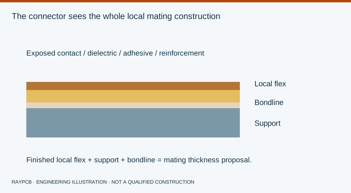
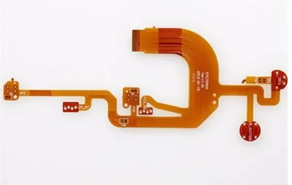
Flex PCB thickness should describe the finished construction at a stated location. A covered moving span, an exposed contact tail and a stiffened component area can have different thicknesses on the same circuit. The base film thickness is not the finished board thickness, and the stiffener sheet thickness is not the completed connector-tail thickness. Define those dimensions separately before matching a connector, enclosure or assembly fixture.
This guide focuses on regional thickness limits and fit. The flex stackup page owns layer-by-layer construction planning; the flexible PCB service page owns manufacturing enquiries. Here you can calculate a local thickness envelope, compare it with an entered mating requirement, and identify missing tolerances. A computed overlap is useful evidence for a review, but it does not demonstrate insertion force, retention, contact pressure or manufacturing yield.
Name the region before assigning the number
| Region | Typical constituents to consider | Drawing question |
|---|---|---|
| Covered flex span | Finished copper, dielectric, adhesive and coverlay | Where and under what method is thickness checked? |
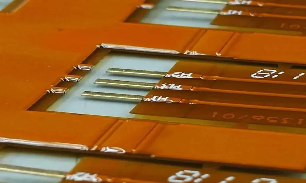
| Exposed finger | Local copper, substrate and specified finish | Which side is exposed, and where does coverlay end? |
| Stiffened tail | Local flex section plus bondline and support | Does the specified mating thickness include all three? |
| Component support | Circuit, adhesive, stiffener and any local coating | Is component height part of a separate assembly envelope? |
| Bonded multilayer region | Each laminate and bonding layer | Is the dimension a pre-press sum or a finished requirement? |
Use named zones on the drawing rather than relying on a general note. A section marked A-A can describe the bend, B-B the contact area and C-C the supported component area. Each should have an identifiable measurement location away from ambiguous edges or steps. If the same physical region has an exposed contact on one side and a support on the other, show both in that section. The operator should not have to infer the missing side from another document.
Surface finish may matter at a tight mating interface, while coverlay may end before that interface. Finished copper can differ from the starting foil. A local adhesive bondline can also vary with the supporting geometry and process. Therefore, a tolerance analysis should use values that correspond to the finished region. Adding purchased-film data can be a useful proposal, but it is not an acceptance range until the manufacturing basis has been reviewed.
A connector-tail tolerance example
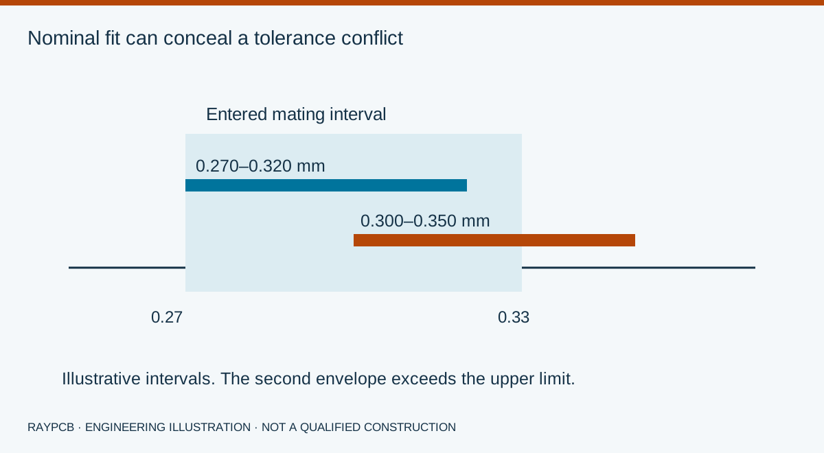
Assume an illustrative connector requirement of 0.27–0.33 mm for its mating tail. The local finished flex is 0.10 ±0.01 mm, the support is 0.17 ±0.01 mm and the bondline is 0.025 ±0.005 mm. The nominal total is 0.295 mm. A worst-case arithmetic envelope is 0.270–0.320 mm. Under those input assumptions, the whole thickness envelope lies within the entered connector interval.
This result says only that the one-dimensional thickness ranges are compatible in the model. It does not approve the cable outline, contact side, exposed length, pitch, reinforcement geometry or insertion procedure. The assumed connector interval is a worked example, not a general FPC connector specification. Obtain the exact part drawing and its controlled revision. Some connectors use a different thickness or a different definition of the reinforced section.
If the support changes to 0.20 ±0.01 mm, the new nominal total becomes 0.325 mm and the envelope becomes 0.300–0.350 mm. The nominal number still lies inside the example interval, but part of the envelope exceeds its upper limit. That is why choosing a sheet because its nominal thickness “looks right” is insufficient. The tool reports full containment, partial overlap or no overlap rather than reducing the decision to a nominal green check.
Compare the local thickness envelope with a mating interval
Enter the finished flex thickness at the actual mating zone, its symmetric allowance, any local support and adhesive with their allowances, and the permitted mating minimum and maximum. Values use millimetres throughout. Set support and bondline to zero only when they are truly absent in that region. The tool rejects an allowance greater than its associated nominal thickness, reversed limits and an empty or physically inconsistent flex thickness.
RAYPCB ENGINEERING
Flex EngineeringFlex Thickness and Connector Interval
Loading Flex Thickness and Connector Interval…
The reported lower margin is the computed minimum minus the allowed minimum. The upper margin is the allowed maximum minus the computed maximum. Positive margins on both sides mean interval containment under the entered assumptions. Zero margin leaves no reserve at that limit. Negative margin identifies the side requiring review. These are geometric margins, not predictions of insertion load, contact reliability or the percentage of acceptable boards.
The export includes each constituent and its source. When you change any input, the previous result and its download become invalid until recalculated. This prevents a customer from attaching a thickness summary that no longer matches a revised support or connector. Use separate exports for different zones or revisions; the tool does not silently merge unrelated regional conditions into one global “PCB thickness.”
Read the actual connector drawing
Connector documentation controls the mating cable dimensions. The Hirose FH12 example part page illustrates that applicable FPC thickness is an explicit product attribute. It is not evidence that every FH series or every ZIF connector accepts the same circuit. Follow the detailed drawing for the exact orderable variant, including contact orientation, cable outline and any reinforcement note. Preserve that reference in the fabrication release.
Determine where the thickness is measured relative to the contact and reinforcement. A stiffener that terminates before the critical insertion zone cannot be counted as though it covers the whole tail. Likewise, a pressure-sensitive adhesive whose final condition depends on assembly may need a separate specification from a bonded film pressed during fabrication. Ask both the connector owner and manufacturer to resolve the definition before selecting a stock support sheet.
If the connector does not provide a convenient interval, do not invent one from its nominal thickness. Request the applicable drawing or engineering clarification. Entering an arbitrary plus/minus allowance into the worksheet can create a convincing but unsupported fit result. The useful action is to expose that missing requirement early, while changing the tail or connector is still practical, rather than discovering it in an assembled sample.
Make thickness measurements comparable
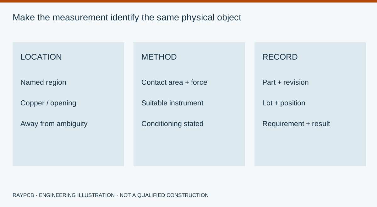
A finished thickness requirement needs a measurement method that is suitable for the construction. Define the location, tool, contact area, force and environmental or conditioning state where relevant. Flexible materials can deflect, and a narrow measuring tip over an etched space may not represent the same section as a broader contact over copper. A report that gives only a number without its location can therefore be hard to interpret.
Avoid comparing a film supplier's nominal gauge with a measurement of a completed covered circuit. They are different objects. Also distinguish local build-up, surface topography and overall assembly height. A tall component is not part of bare-board thickness, yet it may be the controlling envelope for the housing. Keep those measurements in separate drawing fields so a supplier does not solve one requirement while accidentally changing the other.
For incoming inspection, agree the relevant sampling and disposition process with the project requirements. A few measurements within the target interval do not establish the full manufacturing distribution. Conversely, a single result near a boundary should be checked against the measurement setup before a conclusion is made. The goal is a repeatable comparison between the drawing and the correct physical feature, with traceability to the circuit revision and lot.
Why a thickness correction can change the bend
Reducing a connector tail's support may solve insertion fit without changing the moving-span thickness at all. Reducing the base film affects the circuit more broadly and can alter electrical distances and handling. Increasing plated copper can improve one requirement while changing both thickness and flex response. The flex design guidelines provide the corresponding motion and routing checks. Keep the region responsible for each requirement visible in every change request.
The location of a stiffness change is also important. A thicker supported region may force the moving section to bend closer to its edge. Merely meeting the connector's thickness requirement does not demonstrate that the adjacent unsupported circuit can accommodate the installed motion. Review the support boundary, clamping location and actual mechanical path. If repeated movement occurs, retain a separate verification plan tied to the finished construction.
Thermal and moisture conditions can also be relevant to dimensional interpretation and service behavior. Use exact material documentation and a controlled manufacturing route; do not infer a completed circuit's temperature rating from the base film. The stack may include different adhesive systems, coatings and supports. A regional thickness drawing provides a place to identify those constituents before the team starts treating a general “polyimide” description as a complete specification.
Resolve thickness before tooling and procurement
Send the fabricator the exact connector reference, section drawings, permissible thickness intervals, proposed materials and quantities. Identify whether the support must be supplied already bonded or installed later. Specify which dimensions are critical to mating and which are planning values. If the supplier proposes a substitute laminate, bondline or support, recalculate the affected region and review the rest of the design before accepting the change.
For a cost comparison, request alternatives that preserve the same finished acceptance requirement. Two constructions may use different nominal constituent thicknesses while meeting the same final envelope, but they can still differ in process risk, sourcing and qualification effort. Use the flex cost estimator to compare documented allowances after the geometric requirement is clear. Do not loosen a mating tolerance purely to make a budget worksheet show a lower number.
Flex thickness questions
Is 0.1 mm a standard thickness for all flexible PCBs?
No. It may describe one construction or one region. Copper count, dielectric, protection, plating and local support change the finished dimension. A nominal value without a region and tolerance is not sufficient for connector or mechanical acceptance.
Should the stiffener thickness equal the connector's required cable thickness?
Usually the relevant comparison is the completed mating construction, not the support sheet alone. Add the actual local flex and bondline where they are present, and follow the exact connector drawing. The worksheet exposes this arithmetic but cannot determine a missing specification.
Can I use statistical tolerance addition instead of worst case?
Only with an appropriate model and evidence about the process distributions and their relationship. This worksheet deliberately uses simple interval addition. It does not assume independent normal distributions, calculate process capability or estimate manufacturing yield.
Does full interval containment approve the connector assembly?
No. It addresses one dimension under your assumptions. Cable width, contacts, outline, reinforcement position, insertion method and electrical performance still need review. Keep a mechanical fit trial and the connector manufacturer's applicable requirements in the release plan.
Bring the requirement and the drawing together
Send the board revision, construction, quantity and the standard or engineering question you need reviewed. Identify unresolved requirements so the response can address them.
Send requirements for reviewOptional: attach the downloaded worksheet manually. This guidance does not certify a design, approve a shipment or replace the applicable authorized standards.