What is a Series Circuit?

pcb design tips

Introduction

A series circuit is a type of electrical circuit in which the components are connected end-to-end in a single loop. The same current flows through each element in a series circuit, but the voltage drops across each component can be different. Understanding series circuits is fundamental for analyzing DC and AC networks. This article provides an in-depth overview of series circuit fundamentals, analysis methods, characteristics, applications, and related concepts.

Series Circuit Basics

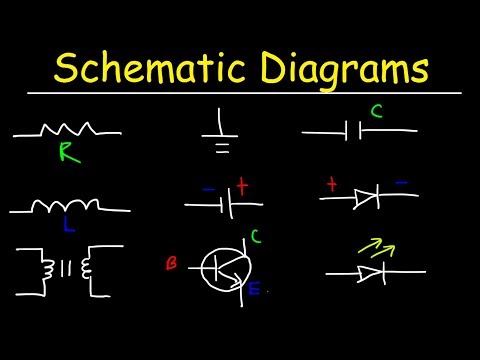
A basic series circuit consists of a voltage source, like a battery, connected to two or more electrical elements like resistors, inductors, capacitors, etc. The elements are chained together with wires in a single path for current flow.

Simple series circuit with battery and three resistors

Some key properties of ideal series circuits:

  • Single loop – Only one path for current to flow around the circuit.
  • Same current – The current is the same at every point due to single path configuration.
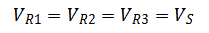
  • Voltage divider – Total voltage equals the sum of the individual voltage drops.
  • Series resistance – Total resistance is the sum of individual resistances.
  • Power distribution – Total power from source is distributed across each element.

These concepts allow systematic analysis of series circuits using basic circuit theory principles.

Series Circuit Analysis

Several important methods are used to analyze series circuits:

Kirchhoff’s Voltage Law (KVL)

This fundamental law states that the algebraic sum of all voltages in a loop must equal zero. This is applied to find unknown voltage drops:

Copy code

Vs = V1 + V2 + V3 + ... + Vn

Where Vs is the total source voltage and V1 to Vn are the individual voltage drops across each element.

For example, in a circuit with a 45V battery and three resistors with voltages V1, V2, and V3, KVL gives:

Copy code

45V = V1 + V2 + V3

If two of the voltages are known, the third can be found by subtracting the known values from the total.

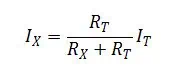
Voltage Divider Rule

The voltage divider rule is a short-cut method to determine the voltage across an individual element using its resistance relative to the total series resistance:

Copy code

Vx = (Vx/RT) * Vs

Where Vx is the voltage across element X, RT is the total series resistance, and Vs is the source voltage.

For example, if R2 is 220ฮฉ, and the total series resistance is 1500ฮฉ, with a 120V source, the voltage across R2 is:

Copy code

V2 = (220/1500) * 120V = 18V

This avoids having to find every intermediate voltage drop.

Current Calculation

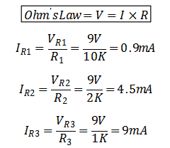
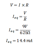
For an ideal series circuit, the current is the same through every element, and can be found from Ohm’s Law:

Copy code

I = Vs / Rt

Where I is the constant current in Amps, Vs is the source voltage, and Rt is the total resistance from adding all individual resistances.

Power Ratings

The power dissipated in each element is calculated as:

Copy code

P = I2 * R

Where P is power in Watts, I is the series current, and R is the element’s resistance.

The total power dissipated is the sum of the individual powers.

Characteristics of Series Circuits

Beyond the basic principles, series circuits exhibit some key characteristics:

Current is Constant Everywhere

Due to the single path configuration, current cannot vary within a series circuit. Each passive component must have the same current flowing through it. This makes analysis using a single loop current straightforward.

Voltage Divider Effect

The total source voltage is divided up across each element proportional to its resistance, according to the voltage divider rule. Elements with lower resistance have larger voltage drops than high resistance components.

Resistance Adds in Series

For the overall circuit, series resistances simply add together. This holds true even for nonlinear devices like diodes or lamps, when their incremental resistances are added.

Impedances Add in General Series Connections

When reactive elements like inductors or capacitors are connected in series, their impedances add together rather than just resistances. For example, three impedances Z1, Z2 and Z3 in series have a total impedance of:

Copy code

Ztotal = Z1 + Z2 + Z3

Current Leads Voltage in Inductive Series Circuits

In a series L-R circuit, the current leads the voltage across the inductor due to its reactance. The opposite happens with a series C-R circuit, where current lags voltage.

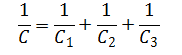
Parallel Resistances Concept

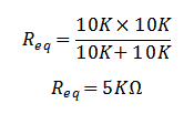
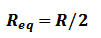
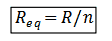
Any branch resistance in parallel can be reduced to an equivalent series resistance using:

Copy code

Rseries = (R1*R2)/(R1+R2)

This allows simplification of branches to a single equivalent resistor.

Simple Series Circuit Examples

Example 1

Simple series circuit with two resistors

  • Vs = 10V
  • R1 = 5ฮฉ
  • R2 = 15ฮฉ

We can directly analyze this circuit as:

  • Total resistance:
    • Rt = R1 + R2 = 5ฮฉ + 15ฮฉ = 20ฮฉ
  • Circuit current:
    • I = Vs/Rt = 10V/20ฮฉ = 0.5A
  • Voltage drops:
    • V1 = I*R1 = (0.5A)(5ฮฉ) = 2.5V
    • V2 = I*R2 = (0.5A)(15ฮฉ) = 7.5V
  • Total voltages:
    • V1 + V2 = 2.5V + 7.5V = 10V = Vs

Using KVL and Ohm’s law gives the same results, verifying the analysis.

Example 2

  • Vs = 120V
  • R1 = 10ฮฉ
  • R2 = 30ฮฉ
  • R3 = 15ฮฉ
  • R4 = 20ฮฉ
  • Total resistance:
    • Rt = R1 + R2 + R3 + R4 = 10ฮฉ + 30ฮฉ + 15ฮฉ + 20ฮฉ = 75ฮฉ
  • Circuit current:
    • I = Vs/Rt = 120V/75ฮฉ = 1.6A
  • Individual voltage drops:
    • V1 = I*R1 = (1.6A)(10ฮฉ) = 16V
    • V2 = I*R2 = (1.6A)(30ฮฉ) = 48V
    • V3 = I*R3 = (1.6A)(15ฮฉ) = 24V
    • V4 = I*R4 = (1.6A)(20ฮฉ) = 32V
  • Total voltages:
    • V1 + V2 + V3 + V4 = 16V + 48V + 24V + 32V = 120V = Vs

Again, methodical analysis using series concepts matches the expected results.

Advanced Series Circuit Analysis

More complex scenarios involve combined resistance and reactance, or nonlinear elements like diodes:

Series RLC Circuit

  • Analysis involves vector addition of complex impedances
  • Impedances must consider both resistive and reactive parts
  • Allows determining overall circuit resonance and current

Series Diode Circuit

  • Must consider diode IV curve and nonlinear resistance
  • Resistance changes with current flow due to diode conduction voltage
  • Allows analyzing diode biasing and turn-on based on series resistance

These advanced tools enable thoroughly analyzing complex series circuits with diverse elements.

Common Applications of Series Circuits

Some typical applications that leverage series circuits:

Voltage Dividers

One of the most common uses of series connections is for creating voltage dividers. For example, measuring a high voltage using two resistors in series, where the lower resistor converts the high voltage into a lower measurable value.

Current Limiting

A resistor or inductor in series can purposely limit the current in part of a circuit. This protects components from excessive currents.

Impedance Matching

Inserting series inductors or capacitors allows matching the impedance looking into a circuit to the desired source/load impedance for maximum power transfer and efficiency.

Voltage Regulation

A series linear regulator uses a voltage sensing resistive divider combined with a series pass transistor to maintain a steady DC output voltage even with variations in supply voltage or load current.

EMI Filtering

Series inductors and capacitors can filter out electromagnetic interference by blocking high frequency noise while allowing lower frequency signals to pass through.

Signal Coupling

A series capacitor can couple AC signals from one stage to another while blocking DC voltages, allowing simple isolation of AC amplified signals.

Related Concepts

Open Circuit

If a break occurs in a series circuit, it becomes an open with no current flow. This is equivalent to a series element with infinite resistance blocking current.

Short Circuit

When two nodes in a series circuit contact each other, a “short circuit” occurs that bypasses part of the series loop. This often leads to excessive currents and is to be avoided in most cases.

Parallel Circuits

In contrast to series, parallel circuits provide multiple paths for current flow. Complex networks combine series and parallel connections, which are analyzed with techniques like nodal analysis or mesh current methods.

Series-Parallel Circuits

Some circuits contain both series and parallel combinations within an overall network. These compound connections can be reduced to simplified series-parallel equivalents for analysis.

Series Resonance

In series RLC circuits, resonance occurs when the total series impedance is minimized at the resonant frequency. This creates a bandpass filter effect around this frequency.

Series DC Motors

DC motors have the field and armature windings connected in series. This results in high starting torque since the initial current is limited only by the total resistance.

Conclusion

In summary, series circuits provide a fundamental topology for analyzing electric networks and understanding key concepts including current, voltage division, resistance addition, and load power distribution. While ideal series connections represent the basics, practical circuits require considering complex impedances, nonlinearities, and combined series-parallel networks. Facility with series circuit techniques forms the foundation for more advanced circuit analysis and design for electronics and power systems.

Frequently Asked Questions

What are the main characteristics of an ideal series circuit?

The key characteristics are: single loop topology, same current throughout, total voltage divides across elements, total resistance is the sum of individual resistances, and total power from source distributes among the components.

Why is current constant at every point in a series circuit?

Due to the single path configuration, charge carriers have no alternative route to flow so the current cannot change within a series circuit. Each element must pass the same current in steady state.

What happens if one resistor opens in a series circuit?

If one resistor opens, creating infinite resistance, current flow would stop. An open resistor is equivalent to disconnecting that part of the loop, so the circuit becomes open and voltage drops across the remaining components go to zero.

How do you calculate total resistance in a series circuit?

The total resistance is simply the arithmetic sum of the individual resistances. This holds true for any passive linear resistive elements. For nonlinear components, incremental resistances must be summed at the operating point.

Why is voltage division important in series circuits?

The voltage divider effect allows finding voltages across individual components from their resistances and the total voltage. This avoids tediously finding voltage drops across each preceding resistor to determine the voltage across a specific element.

How to Download and Use Eagle PCB Software

EAGLE CAD

Introduction to Eagle PCB Software

Eagle (Easily Applicable Graphical Layout Editor) is a popular printed circuit board (PCB) design software developed by CadSoft and now owned by Autodesk . It allows electronic engineers and hobbyists to easily design schematics and PCB layouts for various electronic devices and circuits .

Some key features of Eagle include :

  • Schematic capture editor for creating circuit schematics
  • PCB layout editor for designing PCBs
  • Auto-router for automatically routing PCB traces
  • Extensive component libraries with over 7000 parts
  • Support for importing/exporting Gerber files
  • Forward & back annotation between schematics and PCB
  • Multi-sheet schematics
  • Real-time DRC (Design Rule Checking)

With Eagle, you can take a circuit idea from schematic design to PCB ready for fabrication. Its easy-to-use interface and powerful features make Eagle a great choice for hobbyists, students, and engineers alike .

In this comprehensive guide, we will cover everything you need to know about using Eagle PCB software .

Downloading and Installing Eagle

EAGLE PCB

To start using Eagle, you first need to download and install it on your computer . Here are the steps:

  1. Go to theย Autodesk Eagle homepageย .
  2. Click on the “Free Download” button to download the latest version of Eagle .
  3. Once the download completes, run the installer executable file .
  4. Follow the installation wizard, accept the license agreement, and choose the installation location on your computer .
  5. Make sure to install Eagle’s bundled utilities like CAM processor and 3D viewer if prompted .
  6. After installation completes, Eagle will launch automatically. You can also find it under Start Menu > All Programs > Autodesk > Eagle .

That’s it! Eagle is now installed and ready to use on your Windows or Mac computer .

Creating Your First Schematic

Once Eagle is installed, it’s time to create your first schematic design . Here are the basic steps:

  1. Launch Eagle and click on File > New > Schematic .
  2. In the new schematic window, you can add components like resistors, capacitors, ICs etc from the libraries .
  3. Components can be rotated or mirrored as needed, and wires drawn to connect them .
  4. Name the components and wires to identify their connections .
  5. Once the schematic is complete, run Electrical Rule Check (ERC) to catch any errors
  6. After verifying the schematic, switch to Board layout view or run autorouter to design PCB

Let’s run through an example of designing a simple LED flasher circuit :

  • Add components like resistor, capacitor, transistor, LED etc .
  • Arrange them neatly and connect with wires .
  • Name components/nets properly like VCC, GND, Input etc .
  • Run ERC, fix any errors like missing connections .
  • Create a new Board layout, route PCB traces manually or auto-route .

With your first schematic completed, you can easily progress to more complex designs in Eagle!

Key Features of Eagle

Now that you’re familiar with Eagle’s basic workflow, let’s highlight some of its key capabilities that make the software so versatile (h3):

Schematic Editor

Eagle’s schematic editor provides all the tools you need to create circuit diagrams :

  • Intuitive graphical interface for drawing schematics
  • Drag-and-drop parts from libraries
  • Annotation tools for labeling components/nets
  • Forward & back annotation with PCB layout

Board Layout Editor

The board editor allows seamless transition from schematics to PCB design :

  • Powerful features like move, copy, group, and rip-up routing
  • User-configurable design rules for efficient layout
  • Auto-routing for taking care of complex routing
  • adjustable board dimensions and multiple layers

Component Libraries

Eagle comes bundled with a expansive component libraries :

  • Over 7000 ready-made footprints and symbols
  • Parameters like package type, pin layout etc.
  • Flexible search tools to find parts
  • Support for creating custom parts and libraries

Manufacturing Output

Eagle facilitates taking your designs from concept to fabrication :

  • Generates industry-standard Gerber and drill files
  • CAM processor for gerber and NC drill file generation
  • 3D step viewer to visualize PCB designs
  • Design rule checking to avoid fabrication errors
  • Export options like PDF/images for documentation

With these powerful features, Eagle provides a complete PCB design suite for any project!

PCB Layout Design Tips

PCB Antenna Layout
PCB Antenna Layout

While transitioning from schematics to PCB layout in Eagle, keeping some best practices in mind will ensure your design goes smoothly :

  • Maintain proper clearance between traces based on voltage levels
  • Keep high voltage traces short and provide enough isolation
  • Route clock signals before other traces for signal integrity
  • Avoid right angle or acute angle traces, use 45ยฐ angles when possible
  • Use ground and power planes on inner layers for noise isolation
  • Distribute bypass/decoupling capacitors evenly over the board
  • Keep matched length for traces like differential pairs and clock signals
  • Minimize trace length variations between related signals
  • Plan component placement to minimize track lengths
  • Verify design rules like width, spacing, mask etc. before manufacturing

Proper PCB layout techniques will ensure your design performs as expected when manufactured. Eagle gives you all the tools to implement these best practices.

Downloading Components and Libraries

Eagle comes bundled with a large selection of ready-made components and symbols. However, you will often need additional specialized parts for your designs . Here are some ways to obtain new libraries and footprints :

  • Check Eagle’s default libraries for missing part numbers
  • Search for the part on SnapEDA website
  • Manufacturer websites often provide Eagle libraries
  • GitHub has many user-submitted Eagle libraries
  • Use Eagle library editor to create custom components
  • Check community forums like Eagle element14 for part requests
  • Contact the manufacturer directly for official models
  • Consider using generic substitute parts for prototyping

With access to additional libraries, you can design using all the parts required for your project!

Tips for Working Faster in Eagle

Like any software tool, there is a learning curve to using Eagle efficiently. Here are some tips to help you be more productive :

  • Use keyboard shortcuts for common tasks like copy, paste, rotate
  • Group related components using Smash to move together
  • Create schematic fragments for repeating circuit sections
  • Use replication tools for placing array of similar parts
  • Add parts/footprints to Favorite toolbar for quick access
  • Usescripts to automate repetitive processes
  • Move circuits between sheets for organized multi-sheet schematics
  • Use Design Rule Check often to avoid layout issues
  • Create custom commands to optimize work as per your needs

Don’t be afraid to tweak Eagle to suit your design style and speed up repetitive tasks. Mastering these tips will help boost your productivity.

Eagle Versions and Licensing

Eagle is available in different variants to suit the needs of students, hobbyists and professionals :

  • Eagle Free – Limited to 2 signal layer boards up to 160cm2. For hobbyists and learning.
  • Eagle Standard – 6 signal layers, 4 power planes, up to 4X size vs free. Starts at $470/year.
  • Eagle Premium – 12 signal layers, up to 12X size vs free. Starts at $1240/year.
  • Educational Licenses – Discounted prices for students and educators.

The paid versions allow more complex multi-layer designs and larger board sizes for fabrication. They also include premium technical support and additional features like Autodesk Fusion integration.

Even the free version of Eagle provides sufficient capabilities for most hobbyist projects and early prototyping needs. Upgrading to a paid license later as your skills and requirements advance is recommended.

Frequently Asked Questions

eagle pcb design

Here are some common questions asked by Eagle users :

What are the system requirements to run Eagle?

Eagle requires relatively modest hardware to run well:

  • Windows 7 or newer, or Mac OS X 10.11+
  • Intel Pentium 4 or AMD Athlon 64 processor
  • 2 GB RAM recommended
  • 1 GB free HDD space
  • Graphics card with OpenGL 2.0 support

Make sure your computer meets these prerequisites before installing Eagle. Having sufficient RAM and graphics capabilities is important for performance.

How is Eagle different from KiCad?

KiCad and Eagle are both popular open source PCB design suites with some key differences :

  • Eagle has more polished and intuitive user interfaces
  • KiCad offers more flexibility and extensibility for advanced users
  • Eagle has more extensive component libraries and models
  • KiCad is completely free and open source
  • Eagle free version has size restrictions
  • KiCad handles large multi-layer boards better

For beginners, Eagle may be easier to learn due to better documentation and UI. As your expertise grows, exploring KiCad for more customization may be worthwhile.

Does Eagle work on Linux?

Unfortunately, Eagle does not have an officially supported Linux version currently .

However, you can run Eagle on Linux using Wine emulator or by setting up a Windows VM within Linux. Many users report being able to use Eagle quite well through these methods.

So while not ideal, Linux users still have options to run Eagle for their PCB designs needs.

Can I export Eagle designs to other EDA tools?

Yes, Eagle can export design files and drawings to formats compatible with other PCB CAD tools :

  • Exports board/schematic images (PNG, JPEG etc)
  • PDF/Postscript exports for documentation
  • ASCII export for netlists and coordinate data
  • Industry standard Gerber/drill files for fabrication
  • IPC-356 testpoint netlist format

This interoperability allows you to transfer designs between different EDA platforms if required.

Does Eagle work on Apple Silicon/M1 Macs?

Yes, Autodesk recently announced official support for Apple M1 chips in Eagle 9.6 version and newer .

So Eagle should work smoothly through Apple’s Rosetta emulation layer on M1 Macs now. However, best performance is still seen on Intel-based Macs. (h4)

Conclusion

In summary, Eagle provides a feature-rich yet easy to use PCB design platform for engineers, students, and electronics enthusiasts alike (h2). With its seamless schematic-to-layout flow, extensive component libraries and wide file format support, Eagle enables you to bring your circuit ideas alive as physical PCBs easily.

The free license allows you to get started with PCB design for basic projects without any cost. Paid licenses provide more advanced capabilities as your skills grow.

With some practice and learning, Eagle’s intuitive tools will help you create clean, fabrication-ready designs quickly and efficiently. I hope this guide provided a helpful overview of getting started with Eagle CAD software for your next electronics project!

What Are the Rules of a Parallel Circuit?

Introduction

A parallel circuit is a closed loop electrical circuit that contains two or more electrical components such as resistors, inductors, capacitors, voltage sources, or current sources that are connected between the same two nodes. The basic configuration of components connected in parallel is that they share two common nodes and each component has its own two terminals or leads.

Parallel circuits are one of the two most basic arrangements for electrical networks, along with series circuits. But parallel and series circuits behave very differently in terms of voltage drops, current flow, resistance, and power dissipation. Understanding the rules and properties that govern parallel circuits is key for circuit analysis and effective electrical design.

Current Flow in Parallel Circuits

YouTube video

One of the defining characteristics of parallel circuit configurations is the way current flows when voltage is applied. The basic rules for current flow through the individual branches of a parallel circuit are:

  • The total current supplied by the source is equal to the sum of the branch currents flowing through each parallel component.
  • The current through each branch pathway is determined solely by the voltage applied and the resistance/impedance of that branch alone according to Ohm’s Law.
  • Each parallel branch has the same voltage drop across it equal to the source voltage.
  • The voltage drop across each branch is identical. Adding additional parallel branches does not affect the voltage across each existing branch.

This is illustrated in the simple parallel circuit below with three resistive branches. When a 12V source is applied, each resistor drops 12V across it. The source current equals the sum of the individual branch currents based on their respective resistances:

So in summary, the defining rules for current flow in parallel circuits are:

  • Total current is equal to the sum of branch currents
  • Voltage drop is the same across each parallel branch
  • Branch currents are determined by branch resistance and obey Ohm’s Law

Calculating Equivalent Resistance

Although each branch in a parallel circuit sees the same voltage drop, the overall circuit can have an equivalent resistance different than the individual resistances. The combined or equivalent resistance of a parallel circuit can be calculated using the formula:

$$R_{eq} = \frac{1}{\sum\limits_{k=1}^n\frac{1}{R_k}}$$

Where:

  • $R_{eq}$ is the equivalent resistance
  • $n$ is the number of parallel resistors
  • $R_k$ is the individual resistance of branch k

For the simple parallel example circuit above, this would be:

$$R_{eq} = \frac{1}{\frac{1}{10\Omega} + \frac{1}{20\Omega} + \frac{1}{30\Omega}} = 6\Omega$$

This combined resistance is lower than any of the individual resistances. Adding more parallel branches decreases the equivalent resistance as more current pathways are available.

Power Dissipation in Parallel Circuits

The power dissipated in each resistor in a parallel circuit follows the expected Ohm’s Law relationship:

$$P = I^2R$$

Where $I$ is the current through that resistor and $R$ is its resistance.

However, an important rule of parallel circuits is that the total power dissipated by the overall circuit is equal to the sum of the power dissipated in each branch:

$$P_{total} = P_1 + P_2 + … + P_n$$

So even though currents divide between parallel branches, powers add up. For the example circuit, the total power from the 12V source is:

$$P_{total} = I_1^2R_1 + I_2^2R_2 + I_3^2R_3 = 1.2W + 0.48W + 0.32W = 2W$$

This demonstrates that the source must provide enough power to match the sum of the power demands of the individual branches.

Applications and Examples

Parallel circuits are very common in electrical engineering applications. Some examples include:

  • Batteries in parallel – Batteries are often connected in parallel to increase the total current available from the power source. The voltage remains the same.
  • Electrical outlets – Outlets in a building are connected in parallel to provide independent power taps that each supply the full voltage.
  • Resistor networks – Parallel resistor combinations are used to create equivalent resistance values that can’t be achieved with a single resistor.
  • Integrated circuits – Very small resistors and other components are fabricated in parallel inside ICs to provide required functionality and performance.
  • Power distribution – High power systems use parallel branches to supply loads from grids and generators to reduce current per branch.
  • Electronics cooling – Fans and pumps can be connected in parallel to provide redundancy if one fails and share the thermal load.

Parallel circuits enable splitting currents, power sharing, redundancy, and circuit isolation. They follow predictable rules that are foundational for more complex circuit analysis.

What Happens in Open and Short Parallel Circuits

Parallel circuits exhibit some unique behaviors when branches are opened or shorted:

Open Branch

If a branch in parallel is opened, that branch no longer conducts current. However, voltage across the remaining branches stays the same.

Total circuit current decreases by the amount that was flowing in the opened branch. Equivalent resistance increases.

Shorted Branch

When a branch is shorted, its resistance drops essentially to zero. This creates a very low resistance path that pulls most of the current.

The shorted branch current is limited only by the source and wiring resistance. Other branch currents decrease. Equivalent resistance decreases toward zero. A direct short often blows a fuse.

So in summary, open branches decrease total current while shorted branches increase total current, assuming an ideal voltage source. These scenarios demonstrate the robustness of parallel circuits.

Troubleshooting Parallel Circuits

Some tips and techniques for troubleshooting issues in parallel circuits:

  • Check branch currents – a missing current indicates an open in that branch. Use Kirchhoff’s Current Law.
  • Check branch voltages – unequal voltages may indicate a bad connection increasing resistance.
  • Check for shorts between branches or to ground causing excessive current flow.
  • Measure equivalent resistance. Higher resistance points to an open branch. Lower resistance indicates a possible short.
  • Look for loose, corroded, or burnt connections causing unwanted changes in resistance.
  • Determine if current is sharing properly between branches. Mismatched resistances can lead to overloads.
  • Inspect components like resistors for physical damage which could produce opens or shorts.
  • Use a simulator to model the circuit and analyze effects of hypothetical faults.

Thorough understanding of parallel circuit rules combined with methodical troubleshooting procedures will help identify and remedy issues.

Comparison of Series vs Parallel Circuits

The properties of series and parallel circuits differ in important ways:

PropertySeries CircuitParallel Circuit
CurrentSame through all componentsDivides among branches
Voltage PolarityDrops add to equal source voltageSame voltage across all branches
ResistanceIncreases with more componentsDecreases with more branches
Power DissipationTotal power equals sum of componentsTotal power equals sum of branches
Component Failure EffectOpen disables circuit, short bypasses other componentsOpen removes branch, short increases total current draw

So while series strings components along one path, parallel branches components across multiple paths exhibiting very different characteristics. Both arrangements are critical to understand.

Frequently Asked Questions

What happens if one resistor opens in a parallel circuit?

If one resistor in a parallel circuit opens, that resistor branch no longer conducts current. However, the remaining parallel branches continue functioning normally. The overall equivalent resistance of the circuit increases. Total current flow decreases by the amount that was flowing in the now open branch. Voltage across each branch remains unchanged. The circuit continues working but at slightly reduced capacity.

How do you determine voltage, current, and resistance in a parallel circuit?

  • Voltage is the same across each branch by the definition of a parallel configuration.
  • Branch currents can be calculated using Ohm’s Law (I=V/R) based on the resistor values.
  • Equivalent resistance is found by taking the reciprocal of the sum of the reciprocals of the branch resistances according to the formula for resistors in parallel.

Why is total current equal to the sum of branch currents in parallel circuits?

This is a result of Kirchhoff’s Current Law which states that the algebraic sum of currents into a node must equal the currents flowing out of that node. In a parallel circuit, the incoming source current splits between the outward flowing branch currents. No current is lost, so the source current must exactly equal the sum of branch currents exiting the node for conservation of charge.

What happens when a parallel branch is shorted?

Shorting a branch provides an alternative low resistance path for current to flow. This will divert current from the other branches to preferentially flow through the shorted branch. The equivalent resistance decreases toward zero. Other branch currents will diminish as the short limits voltage. Eventually a large enough short circuit can draw more current than the source or wiring can provide, blowing a fuse.

How are parallel circuits used in electrical systems?

Some common uses of parallel circuits include:

  • Wiring buildings with multiple outlet circuits in parallel
  • Connecting batteries in parallel to increase capacity
  • Building redundancy into safety critical systems through paralleling components
  • Combining cooling fans and pumps in parallel for greater airflow or circulation
  • Adding capacitor or inductor branches to filter and smooth power supplies
  • Creating resistor ladder networks for analog to digital conversion
  • Sharing current and power demands among parallel branches

So parallel circuits enable splitting and redirecting electrical flows in many useful ways.

Summary

In summary, the key rules and properties that define parallel electrical circuits are:

  • Total current equals the sum of the branch currents
  • Voltage is the same across each parallel branch
  • Branch currents follow Ohm’s Law depending on branch resistance
  • Equivalent resistance decreases as more parallel branches are added
  • Total power dissipated equals the sum of power in all branches
  • Open branches decrease total current, shorted branches increase total current

Understanding parallel circuit fundamentals provides the basis for more advanced circuit analysis and design for electronics, power systems, and other electrical engineering applications.

Parallel Connection in Circuits:

The two components are said to be in parallel if they are connected back to back or end to end. The potential difference or the voltage drop across each component in parallel is same and the current flowing through each component is different.

Example 1 of Parallel Circuit:

Let us understand from a basic circuit example where three resistors R1 (10Kฮฉ), R2 (2Kฮฉ) and R3 (1Kฮฉ) are connected in parallel with each other. Now we will find out the voltage drop across each resistor, current through each resistor and total equivalent resistance of the circuit.

 Parallel Circuit
Voltage

The voltage across each component connected in parallel is the same as the source voltage. Hence

1

Where VS is the source voltage = 9V battery

2
Current:

Now applying Ohmโ€™s Law on each resistor to find current through each one.

3

Hence we can draw a simple table to represent these values

R1R2R3
Resistance (R)10Kฮฉ2Kฮฉ1Kฮฉ
Voltage (V)9V9V9V
Current (I)0.9mA4.5mA9mA

Equivalent Resistance of the Parallel Combination of Resistors:

Rule 1:

The equivalent resistance of the parallel combination of two or more than two resistors is always less than the value of smallest resistor in parallel.

Formula for equivalent resistance of more than two resistors connected in parallel is

Rule 1

Hence we can see that the equivalent resistance (R) is less than the smallest resistance (1K) in parallel.

Rule 2:

The equivalent resistance of two equal value resistors connected in parallel is half of that resistor value.

Formula for equivalent resistance of two resistors connected in parallel is

Rule 2

The rule 1 is also applicable for two resistors

Now let R1 = R2 = R = 10Kฮฉ

rule 2-2
r

Hence we can see that the equivalent resistance is exactly equal to half of the two resistance. We can say that

Rule 3:

In general, if โ€œnโ€ equal value resistors are connected in parallel, their equivalent resistance will be

rule 3

Tips:

  • Convert all the units of resistances in one single unit. The units of resistance is mฮฉ, ฮฉ, Kฮฉ, Mฮฉ
  • For calculation do not consider the milli, Kilo, or Mega units. Simply do math on numbers and add the unit to the final result.

Now back to the example 1, we can draw the equivalent circuit using equivalent resistor. Now we can calculate the total current (I) flowing through the circuitใ€‚

example 1

Total Current or Equivalent Current:

Apply Ohmโ€™s Law again

Ohmโ€™s Law

We can see that this total current is the sum of all the branch currents flowing through each resistor.

Hence we can say that

 total current

Nodes:

The node is the junction point where two or more terminals meet each other.

As we can see that the connection in blue color is shared between all components in parallel.

The node 1 is positive because it is connected to DC power source positive terminal and Node 2 is negative or GND (ground) terminal because it is connected to source negative terminal.

Nodes
Rule 4:

If โ€œnโ€ equal resistors are connected in parallel, they will have equal current flowing through them and that current is

Current

Where  is the total / equivalent current of parallel circuit

Current Divider Rule:

The current divider rule says that the sum of all the branch currents connected in parallel is equal to the total current flowing.

Through the help of current divider rule we can find the individual branch current in Example 1.

The formula of current divider rule is

Current Divider Rule 2

Where

123

As we calculated calculated

Therefore

therefore

Hence it is proved from table.

The above discussion was in context of parallel resistor based circuits. However many other components can be connected in parallel

The parallel combination of resistors is very useful in many circuits where there is a need of a smaller resistor and you only have larger resistors available. Like if you have 2, resistors of 10K then you can make parallel combination to make it a 5K resistor. You can make it 20K also by connecting in series combination. Series combination will be discussed in later articles.

Other Examples of Parallel Circuit:

Parallel RLC Circuit:

The combination of various passive components like resistor, capacitor and inductor can generate different functions. The parallel RLC circuit can be used oscillator circuits, frequency tuning and filter circuits. The application of parallel RLC circuit is basically in AC high frequency circuit however the above discussed resistor RLC circuit is for DC circuit application.

Parallel Battery Bank:

The DC batteries can be connected in parallel combination to make a battery bank with higher AH ratings. Three 18650 batteries each 3.7V/3000mAh connected in parallel will generate an equivalent bank of 3.7V 9000mAh. Thus voltage will remain same but the capacity of battery bank will increase.

Parallel Connected Capacitors:

The capacitors can be connected in parallel to increase the total/equivalent capacitance. The three capacitors C1, C2 and C3 10uF each connected in parallel will make an equivalent of 30uF capacitance (C)

Parallel Connected CapacitorsParallel Connected Capacitors

Electrical Loads Connected in Parallel:

The household electrical wiring is done such that the electrical loads like Fans, Tube Lights, energy savers, Air-conditioners, Washing machines, Iron, Fridge and other appliances are connected in parallel to each other. The 220V/110VAC is supplied equally to each appliance and each appliance will draw current differently according to its wattage/power.

Fault in Parallel Circuits:

Open Circuit:

In Example 1, if one of the three resistors get open circuit, then the current will not flow from that resistor but the current will still flow from other two. The voltage will still be equal upon each resistor.

Short Circuit:

Similarly, if one of the three resistors get short circuit, the voltage drop across all three resistors will become zero. The current will flow at maximum from shorted resistor while the rest of the two resistors will have zero current flow.

What do schematic symbols mean?

Schematic Symbols

Understanding Schematic Symbols

YouTube video

Schematic diagrams use specialized symbols to represent the components and connections in an electrical or electronic circuit. These schematic symbols allow engineers and technicians to design and communicate circuit operations quickly, clearly and efficiently. Learning the meaning of basic schematic symbols is essential for anyone working with electronics.

Some common schematic symbols include:

Resistors

schematic

Resistors restrict or limit the flow of electrical current. The most basic resistor symbol is a zig-zag line:

Resistor value may be indicated by numbers, such as 10K for 10 kiloohms.

Capacitors

Capacitors store and release electrical charge. Basic capacitor symbols show two parallel lines:

Capacitance value may be indicated, such as 0.01uF for 0.01 microfarads.

Inductors

Inductors use coiled wire to create magnetic fields that store energy. Simple inductor symbols show a coiled wire:

Inductance may be indicated, such as 220uH for 220 microhenries.

Transistors

Transistors amplify current or switch signals on or off. Common transistor symbols represent npn or pnp structures:

Transistor leads or pins are labeled B, C, E.

Diodes

Diodes allow current flow in only one direction. The triangle symbol points in the allowed current direction:

Diodes are critical components in rectifiers and voltage regulators.

Integrated Circuits

Integrated circuits contain miniaturized electronic components. IC symbols commonly show a rectangle:

Pins or leads may be individually numbered. Popular ICs include op amps, timers and microcontrollers.

Transformers

Transformers use magnetic cores to transfer electrical energy between circuits. Transformer symbols show two coils of wire around a core:

Transformers step voltage up or down for power supplies.

Switches

Switches open or close circuits electronically or mechanically. Basic switch symbols show open and closed contacts:

Switches route signals and control power in electronic devices.

Batteries

Batteries convert chemical energy into electrical energy. Simple battery symbols show positive and negative terminals:

Battery rated voltage may be shown, such as 9V. Batteries power portable electronics.

Fuses

Fuses protect circuits from excessive current and short circuits. Fuse symbols depict melted wire filaments:

Fuse ratings indicate maximum sustained current, such as 1A.

Relays

Relays switch electrical contacts using electromagnet coils. Relay symbols show an electromagnet coil controlling a switch:

Relays remotely switch high power devices with low power circuits.

Common Electrical Schematic Symbols

In addition to specific electronic component symbols, schematic diagrams use graphical symbols to represent general electrical and electronic concepts:

  • Wires and Connections
    • Solid lines show conductive connections between components.
    • Dashed lines show connections continued elsewhere on the schematic.
  • Ground
    • Ground or earth symbols connect circuits to ground reference.
  • Power Supplies
    • Battery symbols show power inputs to circuits.
    • AC and DC voltage symbols indicate power types.
  • Outputs
    • Speaker, lamp and antenna symbols show signal outputs.
    • Arrows may indicate signal or current direction.
  • Logic Gates
    • AND, OR, NOT, NAND, NOR and XOR gate symbols show digital logic.
    • Logic symbols codify Boolean algebra relationships.

Standardized schematic symbols allow professionals worldwide to accurately interpret circuit diagrams. With practice, even hobbyists can learn to “read” schematics effectively.

Reading and Drawing Schematics

Here are some tips for reading and creating schematic diagrams:

  • Focus on one circuit section at a time. Don’t try to trace every connection at once.
  • Identify each component and its schematic symbol. Recognize its function in the circuit.
  • Follow the current or signal path from input to output. Visualize voltages and waveforms.
  • Note labeled pins, values and polarities. Double check connections.
  • Neatly position and align symbols and wires for clarity. Minimize crossed wires.
  • Use CAD software or pencil on graph paper to cleanly draw schematics.
  • Add descriptive notes. Document component designators, values and functions.

Practice reading basic schematics until visualizing the circuit operations becomes easy and intuitive. Refer to electronics reference guides to look up unfamiliar symbols as needed. With patience and experience, the meaning behind schematic diagrams will become clear.

Schematic Symbols for Common Electrical Components

Beyond the basic symbols for generic resistors, capacitors and other components, more specific symbols indicate the detailed function of devices in circuit diagrams. Here are schematic symbols for several common electrical components:

Fixed Resistors

  • Fixed resistors have specific, constant resistance values.
  • Different symbols indicate resistance tolerance, such as ยฑ5% or ยฑ10%.

  • Temperature coefficients may be specified, like PP for 0.1%/ยฐC.

Variable Resistors

  • Variable resistors can be adjusted to provide different resistance values.
  • Common variable resistor symbols include potentiometers and rheostats.

Linear Regulators

  • Linear voltage regulators output steady DC voltage from an input supply.
  • Symbols show ground, input voltage (Vin) and output voltage (Vo).

LEDs

  • Light emitting diodes (LEDs) produce light from applied voltage.
  • Arrows in LED symbols show light emission direction.

Pushbuttons

  • Pushbuttons connect circuits when pressed. Symbols show normally open or closed contacts.
  • Mechanical action is indicated by curved lines.

Toggle Switches

  • Toggle switches flip between open or closed circuits with a lever.
  • Symbols indicate pole and throw configurations like SPST, DPDT.

  • Throws may change multiple poles simultaneously.

Terminal Blocks

  • Terminal blocks provide temporary electrical connections.
  • Symbol shows fixed board mount location with removable wire terminals.

Test Points

  • Test points or probes allow voltage measurements without altering wiring.
  • Symbols show connections broken for probe insertion.

Audio Jacks

  • Audio jacks make removable plug connections for speakers, microphones or headphones.
  • Symbols show mono or stereo configurations.

Learning the specific schematic symbols for different electrical and electronic devices allows for more complex circuit diagram interpretation. With practice reading schematics containing detailed component symbols, electrical engineering knowledge expands.

Tips for Drawing Electrical Schematics

Creating clear, accurate schematics is essential for documenting circuit designs. Here are some tips for effectively drawing schematics:

  • Plan the layout before drawing. Group related components.
  • Use CAD software or graph paper with pencil for clean results.
  • Neatly align symbols and wires. Minimize crossed wires.
  • Label components with unique designators like R1, C2.
  • Annotate with important component values.
  • Include text descriptions to document operations.
  • Draw schematic pages in logical progression if designing complex systems.
  • Double check all connections and polarities match circuit intent.
  • Verify schematic is fully legible if photocopied or scaled down.

Taking time to practice schematic drawing using proper symbols and techniques will help develop essential electrical engineering documentation skills. Smart schematic design allows effective communication of innovative circuit concepts.

Examples of Complete Circuit Schematics

To reinforce schematic concepts, examine these examples of full schematic diagrams for simple circuits:

LED Flasher Circuit

This schematic shows an astable 555 timer IC pulsing an LED on and off:

  • 555 timer uses R1, R2 and C1 to generate a clock signal.
  • Transistor Q1 amplifies the pulse to drive LED D1.
  • R3 limits LED current.

Voltage Divider Circuit

This schematic demonstrates creating lower voltages from a higher supply:

  • R1 and R2 as a voltage divider reduce 12V to 5V.
  • Transistor buffers 5V output, isolating it from load.
  • Zener D1 provides 3.3V regulated from 5V supply.

Class A Amplifier

This schematic shows a basic transistor class A amplifier:

  • Input AC signal coupled through C1 to base of Q1.
  • Q1 amplifies input, providing gain to output through C2.
  • R1 provides DC bias; R2 is collector load resistor.

These examples illustrate complete schematic diagrams using proper symbols and annotations. With practice, electrical engineering professionals can quickly draw schematics to document circuit designs.

Specialized Electrical Engineering Schematic Symbols

Beyond generic components like resistors and capacitors, specialized schematic symbols represent higher-level electrical and electronic concepts and subsystems. Some examples include:

Motors

  • Motor symbols indicate electromechanical power conversion.
  • Symbols may show DC or AC inputs, rotational direction, speed.

Wires

  • Unique symbols represent different wire types like shielded cable.
  • Colors and gauges may also be shown.

Sensors

  • Sensor symbols identify devices that detect physical stimuli.
  • Inputs like motion, pressure, gas, moisture may be indicated.

Microcontrollers

  • Microcontroller symbols represent programmable digital logic units.
  • Architectures like 8051, PIC, Arduino may be shown.

Telecommunications

  • Symbols show wired telecom interfaces like broadband, DSL.
  • Wireless systems like WiFi, cellular, Bluetooth indicated.

These examples demonstrate some of the many specialized schematic symbols used in electrical engineering subfields. With so many diagram conventions established, schematics remain effective communication tools.

Proper Usage of Schematic Symbols

When drawing schematic diagrams, follow these guidelines for proper usage of symbols:

  • Use standard symbols per industry conventions for clear understanding.
  • Check symbol orientations and polarities carefully.
  • Connect symbols accurately as designed in the real circuit.
  • Neatly align symbols and wires for easy visual tracing.
  • Clearly label components with designators and values.
  • Annotate with notes to explain circuit function.
  • Cross-reference schematic pages for complex systems.
  • Include a legend to define any custom symbols used.

Adhering to best practices for symbol usage results in schematics that can be correctly interpreted by others. Well-executed schematics allow effective design review, discussion and troubleshooting. They preserve circuit knowledge over time.

Carefully learning schematic symbol meanings, applications and drawing methods is time well invested for mastering electrical engineering design communication. With practice, schematics become powerful productivity tools to document innovations and enable collaboration.

Frequently Asked Questions

What are the most common electrical schematic symbols to memorize?

Some of the most common and essential schematic symbols to memorize include:

  • Resistor – zig-zag line
  • Capacitor – parallel lines
  • Inductor – coiled wire
  • Transformer – two coils around core
  • Diode – triangle pointing in direction of current
  • LED – diode triangle with lightning bolts
  • Switch – line with open/closed contacts
  • Battery – long and short parallel lines
  • Ground – three lines fanning out

Memorizing the symbols for these basic components will allow reading and understanding most schematics.

How do you identify components and connections on a schematic?

To identify components on a schematic:

  • Recognize standard symbols for resistors, capacitors, ICs, etc.
  • Read component labels like R1, C2, U1 to distinguish uniquely.
  • Follow connections between symbols to trace current flow.
  • Inspect for key points like power inputs, ground.
  • Check notes for functional explanations.

Methodically inspecting symbols, labels, wires and annotations allows properly interpreting components and interconnections.

Should you draw schematics by hand or use CAD software?

For professional electrical engineering work, CAD software like Altium, KiCad or Eagle is recommended for drawing accurate schematics. CAD tools provide libraries of standardized symbols, neat alignment of connections, and integration for PCB layout and design reviews.

For hobbyists, hand-drawing schematics with a pencil and graph

What is a Current Limit Control Circuit?

High Current PCB

Introduction

A current limit control circuit is an important protection feature implemented in power supplies, battery chargers, motor drives, and other applications where excessive current draw can damage components or cause hazardous conditions. This article provides an overview of current limiting methods, design considerations, and example circuits for implementing adjustable current protection.

What is Current Limiting?

Constant Current Control Circuit Diagram

Current limiting refers to techniques used to maintain the output or input current of a power supply or circuit below a preset maximum level. It serves to:

  • Prevent overcurrent damage to circuits caused by shorts, inrush currents, or faults
  • Limit current to safe levels avoiding risks like overheating, fires, or explosions
  • Allow continued operation but at reduced levels during overload
  • Improve system reliability and safety

Current limiting is implemented by measuring the current and actively controlling it to cap it before it exceeds desired limits.

Methods of Current Limiting

Several techniques can be used to achieve current limiting:

1. Power Supply Current Limiting

  • Most basic method
  • Built-in overload protection feature in power supplies
  • Uses internal current sense resistor to monitor output current
  • Feedback loop reduces or cuts-off output when current exceeds preset limit

2. Current Sensing with Pass Element

  • Pass element like transistor controls current flow
  • Separate sense resistor or amplifier measures actual current
  • Feedback circuit regulates pass element to maintain current within limits

3. Foldback Current Limiting

  • Reduces output voltage in response to increased load
  • Maintains constant current over a wide voltage range
  • Prevents thermal runaway as voltage drops under overload

4. Electronic Current Limiting

  • Fast-acting solid state current sensing and control
  • Uses op-amps, comparators, MOSFETs, etc. for tight regulation
  • Permits multiple threshold levels and complex limiting profiles

Each approach has its advantages and limitations. The choice depends on control requirements, cost, speed, accuracy, and other factors.

Design Considerations for Current Limit Circuits

Some key parameters and factors to consider when designing current limit control circuits:

  • Required current limit levels – Maximum current needed for normal loads and minimum sustaining current for overload conditions.
  • Load characteristics – Steady state, inrush, and transient currents drawn by different loads.
  • Limit response time – Fast response needed for safety while avoiding spurious triggering.
  • Overload thresholds – Voltage/current thresholds to trigger limiting at various levels.
  • Power dissipation – Heat dissipated in sense elements and pass devices.
  • Protection coordination – Limiting coordinated with other protections like fuses, breakers.
  • Monitoring and status – Indicators and flags for system monitoring and diagnostics.
  • Operational modes – Settings for normal/fault modes, latched/auto-reset operation etc.
  • Component tolerances – Tolerances and drift affecting accuracy and repeatability.
  • Environmental factors – Temperature, humidity, noise and their impact on precision.
  • Safety standards – Compliance with relevant safety requirements.

These parameters guide the circuit design, component selection, and firmware programming.

Example Current Limit Control Circuits

Some example implementations of current limit control circuits are:

1. Simple Current Limiting for DC Power Supply

[Block diagram]

  • Low-side pass transistor as variable resistor to limit current
  • Voltage across sense resistor proportional to load current
  • Amplified error compared to reference voltage sets transistor base drive
  • Transistor collector-emitter resistance increased to maintain current within limit

2. Dual-Threshold Current Limiting

[Block diagram]

  • Provides both power and fault current limiting levels
  • Binding post shunts op-amp during power-up to allow higher inrush
  • Once powered, feedback loop limits to continuous current rating
  • Comparator detects overcurrent and drives transistor to much lower fault limit

3. Precision Programmable Current Limiting

[Block diagram]

  • Microcontroller digitally programs DAC based on settings
  • DAC sets reference voltage for transconductance error amplifier
  • Amplifier drives MOSFET pass element controlling output current
  • Closed loop feedback ensures load current matches DAC level
  • Enables multiple programmable thresholds for smart limiting

These demonstrate implementations ranging from basic to sophisticated for different requirements.

Setting the Current Limit Threshold

The current limit threshold is adjusted using:

  • Sense resistor – A higher value resistor results in larger voltage drop for same current. Reducing sense resistor value increases the current limit.
  • Reference voltage – The reference voltage applied to the comparator or amplifier determines the maximum current allowed before limiting action is triggered.
  • PWM/Duty cycle – In switch mode power supplies, the peak inductor current is controlled by PWM duty cycle. Lower duty cycle reduces peak current level.
  • Digital potentiometer – Digitally controlled potentiometers act as adjustable voltage dividers. Changing wiper position modifies reference voltage and current limit.
  • DAC output – Digital-to-analog converters generate reference from microcontroller code. Provides programmable current limit levels.

Implementing Adjustable Current Limiting

Making the current limit user-adjustable can be useful in some applications. Some options are:

  • Variable sense resistor – A potentiometer or rheostat acts as variable sense resistor. Rotate to increase/decrease resistance and current limit.
  • Reference potentiometer – Potentiometer forms an adjustable voltage divider for the reference input to op-amp/comparator.
  • Digital potentiometer – SPI/I2C controlled digitals pots change wiper position to tune current limit.
  • External adjustable voltage – Apply external variable DC voltage to set reference level and current limit threshold.
  • User interface – Buttons, knobs, displays on microcontroller/PLC interface provide adjustable settings.

Careful circuit design is needed to prevent noise, drift, and loading effects that can impact adjustability.

Enhancing Accuracy of Current Limiting

For more accurate current limiting, some enhancement techniques include:

  • Precision sense resistor – Use tight tolerance sense resistors with low temperature coefficient.
  • Input filtering – Add filtering to reduce noise on sense voltage input.
  • Chopper stabilization – Chopper amplifiers minimize offset voltages and drift errors.
  • Calibration – Measure and trim offset voltages/reference for maximum accuracy.
  • Current mirror -Mirror reference current to bypass sense resistor and its errors.
  • Multiple sense elements – Average readings from multiple points to negate localized errors.
  • Feed forward compensation – Compensate for load dependent voltage drops in real-time.

Applications of Current Limit Control Circuits

Some example applications where current limiting circuits are widely used:

  • Switch mode power supplies – Limits peak inductor current in converters.
  • Battery chargers – Prevents damage from excessive charging currents.
  • LED drivers – Limits LED current for thermal management.
  • DC motor drives – Protects against stalled rotor overcurrents.
  • Traction systems – Prevents excessive acceleration currents.
  • Audio amplifiers – Safeguards against short circuits in speaker lines.
  • Electroplating – Regulates current density for uniform plating.
  • Lab power supplies – User-adjustable protection against overloads.
  • Fault current limiters – Blocks very high fault currents while allowing lower nominal currents.

Summary

Current limit control provides vital protection in a wide range of power electronic systems. Designing an effective circuit requires balancing factors like response time, precision, stability, cost, and compliance needs. Classic linear circuits and contemporary solutions leveraging digitally controlled components both offer options for implementing adjustable, multi-mode, and smart current limiting capabilities.

Frequently Asked Questions

What are some key benefits of implementing current limiting?

Current limiting improves reliability and safety by preventing damage from excessive currents. It allows continued reduced operation during temporary overloads. It also reduces risks like overheating, fires, or explosions.

How are different current limit thresholds set in a power supply?

The peak or average output current level at which limiting occurs is adjusted by changing the sense resistor value, reference voltage, PWM duty cycle, digital potentiometer setting or DAC code.

What is foldback current limiting?

Foldback limiting reduces the output voltage proportional to increasing load current, maintaining a relatively constant current over a wide voltage range. This prevents thermal runaway.

Which current limiting method offers the fastest response time?

Electronic current limiting using op-amps, comparators and MOSFETs offers very fast response as it is all solid state. This enables protection down to microsecond timescales.

What parameters influence the accuracy of current limiting?

Sense resistor tolerance and thermal drift, amplifier offsets, noise pickup, reference voltage errors, timing variations in digitally controlled circuits and calibration all affect accuracy.

The constant current control circuit, the output end of the transformer T is connected to the rectifier circuit, wherein the input end of the transformer T is connected with a switch control circuit, the rectifier circuit is connected with the resistor R3, the emitter junction of the triode VT is connected in parallel with the resistor R3, and the set of the triode VT The electrical junction is connected in series with the light-emitting tube of the photocoupler LV, and the output end of the photocoupler LV is connected to the transformer T through a switch control circuit.

YouTube video

The utility model has the advantages of simple structure, ingenious design, low cost, low energy consumption of components, low noise, and constant current of the circuit.

The following figure is the circuit diagram of DC or battery input, and constant current control for 6 strings of LEDs.

It uses a multi-string boost structure design, the LED pcb driver is similar to the previous one, the difference is that the AC input is changed to DC or input by the battery. Low-voltage side sensing design As long as the appropriate MOS tube is selected, the LED can be stringed in a considerable number.

Compared with the AC input scheme, the design is relatively simple. However, due to the extra boost switch, the efficiency is relatively low. The advantage of the scheme is that the design is simple, the circuit cost is low, and the disadvantage is that the efficiency is low.

It is suitable for solar cells or street lights that are input via an adapter.

Constant Current Control PCB Schematic Diagram

How do You Make a Rain Alarm Project?

Introduction

A rain alarm is a useful device that alerts when it starts raining. This allows proactively taking actions like closing windows to prevent rainwater from entering a building. This article provides a step-by-step guide on making a simple rain alarm project using basic electronic components.

The working principle and key stages like circuit design, PCB making, code development, enclosure design and testing will be covered. Additionally, tips to enhance the functionality and aesthetics of the project are provided. A FAQ section addresses common queries regarding rain alarm projects.

Principle of Operation

The rain alarm works on the following principle:

  • A sensor module detects rainfall and outputs a signal.
  • This signal is processed by a microcontroller.
  • When rain is detected, the microcontroller activates an alarm driver circuit.
  • The alarm driver triggers a buzzer to generate an audible alert.
  • An LED is also blinked to give visual indication.
  • If no rain is detected after some time, the alarm is switched off automatically.

Circuit Diagram

The circuit diagram of the rain alarm project is shown below:

It consists of the following key components:

  • Rain sensor module – Detects rain and outputs logic level signal.
  • Arduino Nano – Microcontroller board to process sensor data.
  • Buzzer and LED – Audiovisual indication when rain is detected.
  • Transistor – Works as alarm driver to switch buzzer ON/OFF.
  • Resistors – Current limiting resistors for LED and transistor base.

Working

  • The rain sensor module has an exposed PCB that senses rainfall through a change in electrical conductance between its tracks.
  • When rain is detected, the sensor outputs a logic HIGH signal.
  • The Arduino Nano microcontroller reads this signal on one of its input pins.
  • When a HIGH state is detected, the Arduino turns ON the buzzer and LED by sending a HIGH signal from its output pin to the transistor.
  • The transistor conducts and allows current to flow through the buzzer and LED to activate them.
  • If no rain is detected for some time, the Arduino turns off the alarm automatically.

Circuit Design Details

  • The rain sensor module requires 5V supply and provides a 3.3V logic level output when rain is detected.
  • The Arduino Nano operating at 5V can directly interface with this 3.3V signal without need for logic level conversion.
  • A general purpose NPN transistor BC547 acts as driver to switch the buzzer ON/OFF by Arduino control signal.
  • The buzzer requires 12V supply and draws over 200mA current when activated.
  • A 1K resistor at transistor base limits the current through Arduino output pin.
  • A 470ฮฉ resistor limits current through the LED for visual indication.

Prototype on Breadboard

Before designing a custom PCB, building a prototype on a breadboard allows testing the circuit and making modifications easily.

  • Use jumper wires to connect the components as per the circuit diagram.
  • Double check all connections to avoid shorts or open circuits.
  • Connect the Arduino Nano to your computer and upload the Arduino code given further below.
  • Power up the circuit by connecting the 12V adaptor and 5V from Arduino USB port.
  • Test rain detection by spraying some water droplets. The buzzer and LED should turn ON.
  • Make sure the alarm turns OFF automatically after some time.

PCB Design

A custom PCB makes the project more compact, robust and professional. Some tips for PCB design:

  • Use CAD software like EasyEDA or KiCAD for board layout.
  • Ensure adequate copper trace widths to handle buzzer current.
  • Include power supply filtering capacitors.
  • Use thick traces or polygons for power connections.
  • Design mounting holes for standoffs to secure board inside enclosure.
  • Make provisions for extending sensor wires to place module outside.
  • Add indicator LEDs to show power status.
  • Check footprint compatibility of components.

Coding the Logic

The Arduino program to implement the rain sensing logic with automatic alarm shut off:

cpp

Copy code

//Define sensor pin #define sensorPin 2 //Define alarm driver pin #define alarmPin 6 //Sensor state int sensorState = 0; void setup() { //Configure sensor pin as input pinMode(sensorPin, INPUT); //Configure alarm pin as output pinMode(alarmPin, OUTPUT); } void loop() { //Read rain sensor state sensorState = digitalRead(sensorPin); //If rain detected if(sensorState == HIGH) { //Activate alarm digitalWrite(alarmPin, HIGH); //else if no rain } else { //Turn off alarm digitalWrite(alarmPin, LOW); } //Small delay before checking again delay(100); }

The logic checks the sensor continuously and triggers the alarm only on detecting rain. Else it remains off.

Enclosure Design

A protective enclosure makes the alarm standalone and deployable outdoors:

  • 3D print or laser cut an enclosure box to required dimensions.
  • Make cutouts for buzzer, LEDs, switches etc.
  • Use cable glands for wire connections.
  • Install PCB on standoffs and wire up components.
  • Seal any gaps for waterproofing using silicone gel.
  • Add an extendable mounting arm for positioning sensor outside.
  • Use aesthetically pleasing sounds/indicators.

Testing and Debugging

Rigorously test the rain alarm before final deployment:

  • Check circuits by applying test inputs.
  • Load test alarm by connecting additional buzzer load.
  • Check range by spraying water from different distances.
  • Ensure false triggers are not happening when no rain.
  • Verify automatic shut off is happening after 1-2 minutes.
  • Keep the enclosure outdoors under slight drizzle and heavy downpour to validate performance.
  • Improve water sealing, sound volume or sensitivity if issues are found.

Applications of the Rain Alarm

The rain alarm project has many real-life applications:

  • Install on windows to alert before they get wet in the rain.
  • Use in greenhouses, sheds to indicate leakage.
  • Attach to roof gutters to check for overflow.
  • Use at outdoor events to watch for rain.
  • Alert fishermen so they can take shelter from impending rain.
  • Provide advance warning of rain to farmers.

Future Enhancements

Some ways to improve and add features to the basic rain alarm:

  • Use WiFi to send mobile alerts when activated.
  • Add a wireless receiver horn for remote indication.
  • Incorporate a raindrop flow rate sensor to quantify rainfall.
  • Log data using IoT cloud platforms for weather monitoring.
  • Include automatic window closing mechanism.
  • Solar power the device for remote outdoor operation.

Conclusion

In this article, a step-by-step guide to building a DIY rain alarm project using basic electronic components and modules was provided. The working principle, circuit design, Arduino code, PCB fabrication and enclosure design aspects were elaborated. Tips for testing, troubleshooting and enhancing the functionality were also discussed. The rain alarm presented makes an interesting hobby electronics project as well as serving practical real-life weather monitoring needs. The instructions and details provided will be useful for students, hobbyists and makers to build their own customizable rain alarm systems.

FAQs

Q1. Does the rain sensor require any power supply?

Most basic rain sensor modules are completely passive and do not require any external power. The detection signal output is generated in response to rain droplets.

Q2. Can piezoelectric sensors be used for rain detection?

Yes, piezo discs/elements can output a signal in response to impinging rain drops. But they require support circuitry to process their high impedance charge output.

Q3. How to increase the range of detection?

Use thicker/longer connecting wires between the rain sensor and alarm circuit to increase the detection distance. A wireless radio link can also remotely place the detector.

Q4. Is Arduino the best microcontroller choice?

Arduino provides a simple way to read sensors and control outputs. But low cost microcontrollers like ARM Cortex M0 can also be used with appropriate programming.

Q5. What are typical use cases for the rain alarm?

Typical uses are to alert before windows, skylights get wet due to rain, prevent flooding of sheds, greenhouses, activate coverings for vehicles, warn farmers about rain, etc.

Schematic diagram of electret microphone working principle

The shape of the common electret microphone is divided into two types: the built-in type and the external type.

electret microphone

Machine-mounted electret microphones are suitable for installation in a variety of electronic devices. The common machine-mounted electret microphones are mostly cylindrical in shape, and their diameters are ฯ†6mm, ฯ†9.7mm, ฯ†10mm, ฯ†10.5mm, ฯ†11.5mm, ฯ†12mm, ฯ†13mm, and the pin electrodes are divided into two ends.

YouTube video

There are two types of three-terminal type, the lead type of the lead-in type with the soft-shielded wire and the lead-type type without the lead wire which can be directly soldered on the circuit board. If classified by volume, there are two types: normal type and miniature type.

Working voltage: UDS1.5~12V, commonly used 1.5V, 3V, 4.5V three

Working current: IDS between 0.1~1mA

Output impedance: generally less than 2K (ohms)

Sensitivity: Unit: volt / Pa, domestically divided into 4 files, red dot (highest sensitivity) yellow dot, blue dot, white point (lowest sensitivity)

Frequency response: generally flat

Directivity: omnidirectional

Equivalent noise level: less than 35 decibels

normal type and miniature type

The following schematic is to use the NPN three-stage tube 9014 to make an amplifier circuit for the microphone.

Materials: Universal board / 1.5V dry battery / 1Kฮฉ resistor * 2 / 1Mฮฉ resistor *1 / 9014 NPN three-stage tube 1 / 10uF electrolytic capacitor 2 / mic microphone one (early used in the old recorder)

Schematic diagram of electret microphone working principle

Schematic Diagram  analysis:

The resistor R1 is responsible for supplying the working voltage to the microphone, R2 and R3 are responsible for providing the bias voltage to the tertiary tube, and the capacitor C1 is responsible for coupling the signal of the microphone to the tertiary tube 9014 for amplification, and finally the amplified signal is coupled through the capacitor C2. Returned to the positive level of the microphone line.

9014 has the following magnification levels: A=60-150 B=100-300 C=200-600

(-9014 C 998 used here) D=400-1000

After the QQ chat test, the sound quality is clear and there is no noise. And in a 13 square meter room, there is no problem talking to the microphone one meter. Most importantly, a typical seventh battery can also be powered continuously for several months. The circuit is simple and the parts are few, which provides a good method for the friends with small microphone sound. After the speech is not so tired, the other party can hear clearly.

How to Design voice activated lights?

Introduction

Voice controlled devices are becoming increasingly popular in home automation and assistive applications. The ability to control lights and other appliances simply by voice commands offers great convenience and accessibility. This article provides a step-by-step guide on designing a voice activated light system using modern speech recognition modules and microcontroller boards.

Key stages in the design process including selection of components, circuit design, power supply, programming and testing will be covered. Additionally, tips to enhance the performance, range and capabilities of the system are provided. The article concludes with a FAQ section on common queries regarding voice controlled lights.

System Overview

A block diagram of the voice activated lights system is shown below:

The major subsystems are:

  • Voice Recognition Module – Detects speech commands and converts to electrical signals.
  • Microcontroller – Processes signals from voice module and controls light switching circuitry.
  • Load Driver – Switches lights ON/OFF based on microcontroller output.
  • Power Supply – Provides regulated power to the circuits.

Hardware Selection

The key hardware components required are:

1. Voice Recognition Module

It listens to voice commands and provides equivalent electrical outputs. Some options:

  • Simple audio amplifiers – Low cost but limited control
  • Speech recognition ICs – Offer good performance but may need training
  • Prebuilt modules – Easy to use, provide electrical outputs for commands

For this project, a prebuilt voice recognition module will be used due to its ease of integration.

Recommended Module: DFRobot DFPlayer Mini voice recognition module. Comes pre-trained for simple commands.

2. Microcontroller Board

It processes the speech module output and controls the light switching. Options:

  • Basic microcontrollers – Low cost but involves coding in assembly or C
  • Arduino boards – Convenient due to abundance of code libraries
  • Raspberry Pi – Powerful but higher cost

For simpler integration, an Arduino Uno board will be used. Has ample I/O pins and processing power.

3. Load Driver

Switches the light load in response to microcontroller commands. Options:

  • Mechanical relays – Inexpensive but larger size and wear out over time
  • Solid state relays – No moving parts but need heat sinks
  • Power MOSFETs – Compact and long life if sized properly

A logic level power MOSFET will be used for switching light loads like LEDs.

Circuit Design

The circuit schematic is shown below:

Voice recognition module – Detected voice command output pins connected to Arduino digital input pins.

Arduino Uno – Processes module output and controls MOSFET gate pin for light switching.

Load driver – Logic level N-channel MOSFET acts as a switch to turn light ON/OFF.

Light load – LED strip connected to MOSFET output through current limiting resistor.

Power supply – 12V DC supply provides power to voice module, Arduino and load. Linear regulator supplies 5V to Arduino.

Power Supply

A 12V 2A DC supply provides adequate power for the voice module, Arduino board, load driver and LED light load.

A 7805 linear voltage regulator provides steady 5V supply to the Arduino board from the 12V source. Capacitors help stabilize the voltage levels.

Proper power supply design ensures stable operation of all components.

Programming

The Arduino program to implement voice activated light control:

c

Copy code

// Voice recognition module output pins #define VR_PIN1 2 #define VR_PIN2 3 // Load driver MOSFET gate pin #define LOAD_PIN 8 void setup() { // Set I/O pins pinMode(VR_PIN1, INPUT); pinMode(VR_PIN2, INPUT); pinMode(LOAD_PIN, OUTPUT); // Initialize serial communication Serial.begin(9600); } void loop() { // Check first voice command pin if(digitalRead(VR_PIN1) == HIGH) { // Turn load ON if first command heard digitalWrite(LOAD_PIN, HIGH); Serial.println("Load ON"); } // Check second voice command pin else if(digitalRead(VR_PIN2) == HIGH) { // Turn load OFF if second command heard digitalWrite(LOAD_PIN, LOW); Serial.println("Load OFF"); } // Small delay before checking again delay(100); }

The code continually checks the voice module output pins. If a command is detected, it triggers the appropriate action to switch the light ON or OFF.

Testing and Troubleshooting

Once assembled, the system should be thoroughly tested:

  • Check power supply voltages – 5V for Arduino, 12V for module and load
  • LED test code – Verify Arduino can drive load ON/OFF
  • Voice module output – Observe electrical signal when commands are spoken
  • Monitor serial output on computer to debug issues
  • Adjust microphone sensitivity, placement for reliable detection
  • Add LED indicators to provide user feedback
  • Isolate subsystems and test individually in case of faulty behavior

Enhancing the Design

Some ways to extend the capabilities of the voice controlled lights:

  • Add more voice commands – Control multiple loads, dimming, color changing LEDs etc.
  • Remote control – Use Bluetooth/WiFi modules for smartphone control
  • Multi-room audio – Multiple microphone modules for whole home control
  • Natural language – Use AI speech recognition for more flexible commands
  • Security – Fingerprint/face recognition to restrict access
  • Scheduling – Create automatic time-based lighting scenes

Applications of Voice Activated Lights

Some useful applications of this voice controlled lighting system:

  • Assistive device – Help disabled or elderly people control lights independently
  • Hands-free control – Enable light switching when hands are occupied
  • Energy savings – Lights left on accidentally can be turned off by voice
  • Smart home automation – Control various appliances, not just lights by voice
  • Industrial environments – Allow control without removing gloves or PPE

Conclusion

In this article, a step-by-step guide to designing a DIY voice activated light system was provided. The key components of voice recognition module, microcontroller, load drivers and power supply were selected. The complete circuit schematic, power supply, Arduino code and testing techniques were elaborated. Additional tips were provided to extend the functionality and applications of voice controlled lights. The information provided serves as a practical blueprint for hobbyists, students or designers to build their own customized voice activated lighting solutions.

FAQs

Q1. Can you use a sound sensor instead of voice recognition module?

Sound sensors like condenser mic modules are cheaper but detect all sounds rather than specific voice commands. So they are not as effective for selective voice control.

Q2. Is WiFi required for voice activated lights?

No, WiFi is not required. The voice recognition, lights control and switching are all handled locally using standalone hardware modules. But WiFi can be added optionally for remote control.

Q3. How many lights can be controlled by this system?

The number of lights depends on the power rating of the load driver circuitry used. For the Arduino and MOSFET based design, up to 50-100W of LED lighting can be controlled in most cases.

Q4. Does the microphone need to be near the person?

The microphone should be placed appropriately to clearly receive commands. Lapel microphones or external mics can be used so users do not have to be very close.

Q5. Can you add an automatic shut off timer?

Yes, the Arduino code can be modified to turn the lights off automatically after a preset duration to save energy using a timer variable and the millis() function.

Automotive Sensor Signal Conditioners Overview

Introduction

Modern automobiles are packed with sensors to monitor the various systems and provide critical signals to the engine control unit (ECU). But the raw sensor outputs cannot be directly used by the ECU and need proper signal conditioning to make them usable for control and diagnostics. Signal conditioners play a vital role in interfacing the wide variety of sensors to the ECU in the harsh electrical and environmental conditions seen in automotive applications.

This article provides an overview of the different types of sensor signal conditioning circuits used in automobiles and their importance in sensor interfacing. Key design considerations and implementation methods are also discussed.

Automotive Sensors Overview

Some major sensors used in automobiles along with sensed parameter and typical output:

SensorParameter MeasuredTypical Output
Mass AirflowIntake Air Flow0-5 V
Oxygen (UEGO)Exhaust Oxygen Content0-5 V
Manifold Absolute PressureIntake Pressure0-5 V
Coolant TemperatureEngine TemperatureResistance
Throttle PositionThrottle Plate Angle0-5 V
Cam/CrankshaftRotation Speed/PositionDigital Pulses
Wheel SpeedWheel Rotation SpeedDigital Pulses
AccelerometerLateral/Longitudinal Acceleration0-5 V

This demonstrates the wide variety of sensor signals the ECU has to process – analog voltages, digital pulses, variable resistance. The signals need to be conditioned before they can be digitized by ECU analog to digital converters (ADCs) and used in control algorithms.

Need for Signal Conditioning

The key functions of sensor signal conditioners are:

Gain – Boost weak sensor outputs to improve signal to noise ratio and match ADC input range.

Filtering – Remove out-of-band noise that can cause errors. Anti-aliasing filter for ADCs.

Linearization – Convert non-linear sensor responses to linear format for simplicity.

Impedance Conversion – Alter sensor output impedance to prevent loading effects.

Isolation – Protect ECU from transients and abnormal sensor voltages.

Excitation – Provide stable voltage/current to passive sensors like thermistors.

Compensation – Counteract sensor inaccuracies like shift over temperature.

Standardization – Present sensor data in normalized formats like 0-5V irrespective of sensor type.

Proper signal conditioning is vital for the ECU to get clean, accurate data from the sensors in the harsh, noisy on-vehicle environment. It acts as the interface between sensors and ECU ADC.

Sensor Signal Conditioner Architectures

Sensor signal conditioners can be implemented in different ways:

Discrete Conditioners – Use op-amps, discrete passives on PCBs. High flexibility but large size.

Integrated Circuits – Special ICs tailored for common functions like amplification, filtering. Compact but limited configurability.

FPAAs – Field Programmable Analog Arrays allow reconfiguration of signal chain. Good tradeoff between size and flexibility.

Module Based – Complete sensor interfacing on a module or board including ADC. Medium flexibility and size.

SoC Based – Sensors, signal chain and ADC integrated on a single chip. Highest integration but custom development needed.

Selection depends on size constraints, development cost and customization needs. Module based conditioning provides a good balance and reduces development effort.

Common Conditioning Circuits

Some typical conditioning circuits used with major automotive sensor types are discussed next:

Bridge Sensors

Load cells, strain gauges use a Wheatstone bridge structure. A basic bridge circuit completes the bridge and amplifies the differential output voltage:

The differential gain rejects common mode noises. Adjustable potentiometers are provided for calibration. The amplified output represents the sensed parameter.

Thermistors

NTC thermistors exhibit large resistance changes with temperature. A potential divider topology can convert this to a voltage:

The voltage varies non-linearly with temperature. Linearization using the Steinhart-Hart equation embedded in the ECU firmware gives accurate temperature.

Digital Hall Sensors

Hall effect position sensors like throttle position sensors have a digital PWM output whose duty cycle varies with position. An integrating filter converts this to an analog voltage:

The RC filter integrates the PWM signal to analog. The diode clamps negative cycles. Result is a clean 0-5V varying with position.

Piezoresistive Pressure Sensors

Sensors like the manifold absolute pressure (MAP) sensor use a Wheatstone bridge piezoresistive structure to detect intake pressure. Similar to bridge sensors, a differential amplifier conditions the output:

Differential gain boosts small mV level signals to 0-5V range. Adjustable potentiometers used for calibration.

Capacitive Position Sensors

Non-contacting capacitive position sensors have a variable capacitance output depending on shaft position. It forms part of an RC oscillator:

The oscillator frequency varies with capacitance change, which is demodulated to a analog voltage representing position by using a PLL, counter or ADC frequency measurement.

Magnetic Wheel Speed Sensors

Active wheel speed sensors produce a square wave frequency directly proportional to the wheel speed:

Signal is buffered via a comparator to clean it up before sending to ECU counter input. No analog conditioning required since sensor output is digital pulse train.

Current Loop Sensors

Some sensors like MAF output a current proportional to intake air mass flow rate and require a simple resistor to convert to voltage:

A low value sense resistor converts the 4-20 mA current to a 0-5V voltage for the ECU ADC. Care taken to ensure voltage burden does not affect sensor performance.

Design Considerations

Some key points considered during design of sensor signal conditioning circuits:

  • Sensor output characteristics – magnitude, impedance, linearity, frequency response, etc.
  • Noise and interference – EMI, crosstalk, engine electrical noise, etc.
  • Tolerance to environmental stresses – temperature, vibration, humidity
  • Fail safe provisions – defaults to known state upon failure
  • Effect on sensor function – biasing, loading, source impedance, feedback etc.
  • Diagnostics capability – able to detect open/short sensor faults
  • Protection – prevent damage to ECU from overvoltage and transients
  • Performance over supply voltage and temperature range
  • Cost, size and design effort constraints

Simulations, prototyping and testing ensures the conditioning circuits provide clean, accurate, normalized sensor data to the ECU under all on-vehicle conditions.

Implementation Methods

There are different approaches to implement the sensor signal conditioning circuits:

Discrete – Using separate opamps, discrete resistors, capacitors

Allows precision conditioning but large size, assembly effort

Integrated Circuits – Dedicated sensor interface, amplifier ICs

Small size but limited configuration flexibility

FPAAs – Field Programmable Analog Arrays

Reconfigurable signal chain blocks for decent flexibility

Module Based – Complete circuit on a dedicated PCB module

Self-contained, quick to integrate but moderate flexibility

SoC – Integrated sensor, signal chain and ADC in a single IC

Maximum integration but fully custom mixed-signal IC development needed

Software Based – Digitize raw sensor output and use software algorithms

Configurable but latency, noise can affect control performance

A module-based approach provides a good tradeoff – easy integration with conditioning tailored for each sensor for automotive production use.

Testing and Calibration

YouTube video

Thorough testing of sensor conditioning electronics is needed to ensure proper operation under all conditions:

Functionality Testing – Validates circuit operation over temperature and voltage ranges with known simulated sensor inputs.

Noise Testing – Quantifies noise and distortion levels introduced by the conditioning circuits.

Error Budgeting – Calculates overall system error by considering all component tolerances, drifts and nonlinearities.

Fault Testing – Verifies fail safe behaviors upon open, short or out of range sensor inputs.

Calibration – Potentiometers, digital trims are adjusted based on calibration with sensor reference standards to minimize errors.

Lifetime Testing – Assesses performance degradation due to thermal cycling, vibration, humidity and aging effects. Confirms adequate service lifetime.

The signal conditioning circuits are a vital link between sensors and ECU. Proper design and testing ensures the ECU gets accurate, noise-free data from the wide variety of sensors in the harsh on-vehicle environment over the vehicle’s lifetime. This enables advanced engine management, fuel efficiency, diagnostics and safety features.

Conclusion

An overview of the common signal conditioning methods used with major automotive sensor types has been presented. Discrete circuits based on opamps, integrated amplifier ICs, FPAAs and module based approaches provide flexible solutions for the varying needs of different sensors while meeting challenges like noise, nonlinearities etc. When designed keeping in mind sensor characteristics, environmental conditions, ECU interface requirements and performance constraints, the sensor conditioners reliably acquire and process raw sensor signals into the standardized, accurate data needed by ECUs for precise engine control. Advancements in programmable mixed-signal ICs and miniaturization will enable higher levels of integration and intelligence in sensor interfaces, moving towards more accurate and responsive engine control systems.

Automotive Sensor Conditioners – FAQs

Q1. How does signal conditioning help the ECU analyze sensor data?

Signal conditioning transforms the raw sensor output into a clean, standard format required by ECU ADC and algorithms – amplifying, linearizing, protecting from transients/noise, converting impedance/format etc. This enables accurate measurement.

Q2. What are some important specifications for automotive sensor signal conditioners?

Key parameters are bandwidth, linearity, stability, drift, noise performance, fault tolerance, protection rating, size/weight, reliability, EMI/EMC compliance, temperature range, input/output impedances and flexibility.

Q3. Which type of sensor interface circuit is most suitable for wheel speed sensors?

Wheel speed sensors output a digital pulse train whose frequency is proportional to speed. Only buffering is needed so a basic comparator circuit provides the required conditioning to clean up pulses before input to ECU counter.

Q4. How can capacitive type position sensors be interfaced to an ECU?

The capacitance versus position characteristic can be converted to a frequency using a capacitance-to-frequency converter circuit. The frequency can then be measured digitally by the ECU using a timer input to determine position.

Q5. What are some methods used for linearizing thermistor response vs temperature?

Using microcontroller algorithms to implement mathematical linearization models like Steinhartโ€“Hart model or look-up tables. Analog linearization circuits using resistor networks or diodes to counteract the thermistor nonlinearity.

High Speed Sensor, Detection and Its Schematic Diagram

A wide range of instantaneous speed measurement accuracy of high speed sensor Schematic diagram.

A speed sensor is a sensor that converts the speed of a rotating object into a power output.

The speed sensor is an indirect measuring device that can be manufactured by mechanical, electrical, magnetic, optical and hybrid methods. According to the different signal form, the speed sensor can be divided into analog and digital, sample as below:

Analog and Digita High Speed Sensor

The output signal value of the analog speed sensor is a linear function of the rotational speed, and the output signal frequency of the digital speed sensor is proportional to the rotational speed, or its signal peak interval is inversely proportional to the rotational speed.

The wide variety and wide range of speed sensors is due to the extensive use of a wide range of motors in automatic control systems and automation instrumentation, and strict requirements for accurate measurements of low speeds (such as one turn per hour), high speeds (such as hundreds of thousands of revolutions per minute), steady speeds (such as errors only) and instantaneous velocities in a number of situations. The commonly used speed sensor has photoelectric type, capacitance type, variable reluctance type and speed measuring generator and so on.

Schematic diagram of the speed sensor as below:

The Schematic Diagram of High Speed Sensor

Introduction

A high speed sensor is a type of transducer that can detect and measure high speed motion, vibration or rotation and convert it into an electrical signal for data acquisition and analysis. High speed refers to frequencies above 10 kHz in most applications. These sensors play a vital role in studying high frequency dynamic phenomena in fields like structural health monitoring, machine condition monitoring, automotive industry, avionics etc. The high sampling rate is necessary to capture enough data points for accurate detection and measurement.

Some common applications of high speed sensors include:

  • Vibration and modal analysis of structures like buildings, bridges, aircraft wings etc.
  • Monitoring blade tip deflections in gas turbine engines of jet aircraft.
  • Engine knocking detection in automotive engines.
  • Monitoring machine tool vibration in manufacturing industry.
  • Studying effects of explosions and impacts.
  • Monitoring pressure fluctuations in fluid flow systems.
  • Studying acoustic emissions in materials.

This article provides an overview of different types of high speed sensors, their working principles, key specifications, instrumentation for high speed data acquisition and analysis. Circuit schematics are also included for common sensor interfaces.

Types of High Speed Sensors

Some common types of sensors used for high frequency measurements and their typical frequency ranges are given below:

Accelerometers

They measure acceleration and vibration. Useful frequency range – 0 Hz to over 50 kHz. Common technologies:

  • Piezoelectric – Up to 50 kHz
  • Piezoresistive – Up to 20 kHz
  • Capacitive MEMS – Up to 50 kHz
  • Force balance – Up to 5 kHz

Velocity sensors

Measure velocity of motion directly. Useful frequency range – 0 Hz to 20 kHz. Common types:

  • Moving coil velocity sensors
  • Geophone – 1 Hz to 250 Hz
  • Laser Doppler Vibrometer – Up to 1 MHz

Displacement sensors

Measure displacement and position directly. Useful frequency range – 0 Hz to 20 kHz. Common types:

  • LVDT – Up to 2 kHz
  • Eddy current sensors – Up to 10 kHz
  • Capacitive and inductive sensors – Up to 50 kHz

Pressure sensors

Measure dynamic pressure. Useful frequency range – 0 Hz to >100 kHz. Types:

  • Piezoelectric dynamic pressure sensors
  • Fiber optic sensors – Up to 100 kHz

Force sensors

Measure dynamic force. Useful frequency range – 0 Hz to 50 kHz. Common types:

  • Piezoelectric load washers – Up to 30 kHz
  • Strain gage load cells – Up to 5 kHz

Motion encoders

Measure speed, position, rotation angle. Useful frequency range – 0 Hz to 50 kHz. Types:

  • Optical incremental encoders – Up to 50 kHz
  • Magnetic encoders – Up to 10 kHz

Acoustic emission sensors

Measure high frequency stress waves. Useful frequency range – 20 kHz to 1 MHz. Types:

  • Piezoelectric sensors
  • Fiber optic acoustic sensors

High Speed Sensor Specifications

YouTube video

Some key specifications of high speed sensors are:

  • Frequency response – The sensor should have a flat frequency response over the measurement bandwidth.
  • Sensitivity – Amount of electrical signal output per unit of measured parameter. Higher sensitivity allows resolving smaller signals.
  • Resolution – Smallest detectable change in the measured quantity.
  • Dynamic range – Ratio of the maximum to minimum measurable quantity. Wider dynamic range allows measuring both small and large signals.
  • Phase response – Minor deviations from the ideal 0ยฐ or 180ยฐ phase are acceptable. Large phase errors make data analysis difficult.
  • Noise – Should be low for resolving small signals. Critical for high resolution measurements.
  • Non-linearity – The output should have a linear relationship with the input. Non-linearity causes measurement errors.
  • Crosstalk – Signals from one axis should not affect other axes. Important for multi-axis measurements.
  • Temperature range – Sensor should perform well over required operating temperature range.
  • Size and weight – Important if sensor has to be mounted on structures which have weight and space constraints.

Instrumentation for High Speed Data Acquisition

The sensor output has to be captured by appropriate data acquisition hardware for analysis. Important parameters:

  • Sampling rate – Must be high enough to avoid aliased spectra according to Nyquist criteria. For frequencies up to 50 kHz, 1 MHz sampling rate is usually sufficient.
  • Resolution – Analog to digital converter (ADC) resolution between 16 to 24 bits preferred. Lower resolution limits dynamic range.
  • Bandwidth – Data acquisition system analog bandwidth must be higher than maximum sensor frequency.
  • Number of channels – Important if using multiple sensors for modal testing, NVH testing etc. 8, 16, 32 channels systems common.
  • Signal conditioning – Amplification, filtering required to match sensor output to ADC input range.
  • Antialiasing filter – Low pass filter before ADC to prevent aliasing.
  • Data transfer speed – Must be fast enough to stream data to processor memory from high sampling rates.
  • Triggering – Required to start data capture at specific events. Important for transient events like impacts.
  • Data acquisition software – Manages hardware settings, data streaming, storage and analysis features.

High Speed Sensor Interfacing Circuits

Some common sensor interfacing circuits are shown below:

ICP Accelerometer Interface

ICP (Integrated Circuit Piezoelectric) accelerometers require constant current excitation for proper functioning. The ICP sensor conditioner provides 2-20 mA constant current and converts the sensor output voltage to a low impedance voltage proportional to acceleration. The low pass filter removes frequencies above the sensor range. The amplifier gain is set to match the ADC input range.

AC-Coupled Accelerometer Interface

AC coupled interface is suitable for accelerometers with voltage mode output. The high pass filter blocks the DC component and provides the AC acceleration signal centered around 0V. The gain stage amplifies the signal to match the ADC input range.

Differential Velocity Sensor Interface

Geophone velocity sensors have a differential coil output. An instrumentation amplifier converts this to a single ended low impedance voltage for digitization. The amplifier gain is set based on the geophone sensitivity and ADC input range.

Bridge Sensor Interface

Strain gages, load cells etc. have Wheatstone bridge type outputs. A bridge completion resistor converts this to a differential voltage input for the instrumentation amplifier. The amplifier gain calibrates the output to engineering units like force, acceleration etc.

Potentiometric Displacement Sensor Interface

Potentiometric displacement sensors like LVDTs have a voltage divider output proportional to position. A difference amplifier converts this to a single ended low impedance output representing the displacement. Excitation voltage must match LVDT specifications.

Digital Encoder Interface

Digital incremental encoders provide quadrature TTL/CMOS pulse outputs for position and speed sensing. A high speed counter chip captures and processes the pulses to give position data. The counter resolution and speed determine the measurement resolution.

High Speed Data Analysis

The captured time domain sensor data is processed using digital signal processing techniques for relevant frequency and time-frequency domain information.

Time Domain Analysis

Analysis in time domain involves:

  • Plotting sensor output vs. time
  • Statistical measures like RMS, peak, crest factor etc.
  • Time waveform parameters like rise time, overshoot, settling time
  • Time domain averaging for improving signal to noise ratio

Frequency Domain Analysis

  • Fourier Transform to get frequency spectrum
  • Analyze dominant frequencies
  • Compare vibration levels at different frequencies
  • Identify resonances
  • FFT spectrum averaging for reducing variance
  • Order analysis for rotational equipment

Time-Frequency Analysis

  • Short Time Fourier Transform (STFT)
  • Wavelet Transform
  • Understand non-stationary signal characteristics
  • Analyze transients and machine start-up data

Modal Analysis

  • Extract modal parameters like frequency, damping, mode shapes
  • Operational modal analysis techniques
  • Finite Element model correlation
  • Structural health monitoring

Proper sensor selection, instrumentation and analysis help gain valuable insights from high speed dynamic measurement data.

High Speed Motion Detection Techniques

Detection and measurement of high speed motion has applications in diverse fields including manufacturing, transportation, material testing, biomechanics and more. Some key techniques used for high speed motion detection are:

1. Laser Doppler Vibrometry

  • Non contact measurement using Doppler shift of reflected laser beam
  • Resolves nano and micron level vibrations up to 10 MHz speeds
  • Low noise, high frequency response
  • Measures displacement, velocity, acceleration
  • Used for MEMS devices, acoustic measurements etc.

2. Stroboscopic Video Motion Analysis

  • High speed video camera with stroboscopic illumination
  • Motion appears slowed down under strobed light
  • Allows visualization of fast periodic motion
  • High recording speeds up to 100,000 fps
  • Used for speaker diaphragm, rotating machinery motion analysis

3. Photon Doppler Velocimetry

  • Measures velocity by light scattered from moving particles in flow
  • Provides instantaneous whole field velocity distribution
  • Used extensively in fluid mechanics, combustion research
  • Velocities up to supersonic speeds measurable

4. Capacitive and Inductive Sensors

  • Non contact displacement measurement
  • High frequency response up to 100 kHz
  • High resolution and sensitivity
  • Small and compact for embedded applications
  • Used for proximity sensing, precision position control

5. Piezo Film Sensors

  • Thin piezoelectric polymer films used as sensors
  • Measure stress, strain, vibration, pressure
  • Broad frequency range up to 1 MHz
  • Highly flexible, can be bonded/embedded
  • Used for acoustic emission, structural health monitoring

6. MEMS Inertial Sensors

  • MEMS accelerometers, gyroscopes for motion sensing
  • Detect acceleration, angular rate, vibration
  • High bandwidths up to 50 kHz
  • Low cost, small size
  • Used in IMUs, condition monitoring, navigation

Proper selection of detection technique is key for successful high speed motion measurement and analysis.

Schematic Diagram of a High Speed Data Acquisition System

A typical high speed data acquisition system consists of sensors, signal conditioning, DAQ hardware, analysis software as shown in the schematic diagram:

  • The sensors transduce the high speed physical phenomenon into electrical signals. Different types of sensors can be used based on the quantity to be measured.
  • Signal conditioning circuits like amplifiers, filters provide gain, filtering, offset adjustment, common mode rejection etc. to match the sensor output to the DAQ input range.
  • High sampling rate DAQ device digitizes the conditioned analog signals via an antialiasing filter and ADC. Synchronized multi-channel capture is enabled by a common clock and trigger.
  • Data is transferred over high speed ports like USB, Ethernet to the analysis software on PC. Buffering helps prevent data loss.
  • Analysis software has capabilities for time domain waveform display, frequency spectra, order analysis, modal analysis etc. Report generation, data export facilities are included.

Proper schematic design is key for accurate acquisition of high frequency signals and extracting useful information through digital signal processing techniques.

Conclusion

High speed sensors and data acquisition systems enable detailed analysis of high frequency dynamic phenomena that cannot be captured using traditional sensors and DAQ devices. With recent advances, frequencies up to 1 MHz can be reliably measured using MEMS sensors, fiber optic sensors and compact DAQ devices.

Selection of appropriate sensors based on frequency range, operating conditions and output characteristics is vital. Suitable signal conditioning ensures the sensor output is correctly interfaced to the DAQ system. High sampling rates, resolution and bandwidths are essential to avoid aliasing and allow detection of small signals.

Powerful analysis software provides the tools to transform the captured time domain data into useful frequency, order and modal domain information through transforms, spectral analysis and other techniques. This high speed dynamic data is critical for condition monitoring, predictive maintenance, product design validation and other applications.

Frequently Asked Questions (FAQ) related to High Speed Sensors

Q1. What is the key difference between a high speed sensor and a regular sensor?

The main difference is the frequency response. High speed sensors can measure dynamic signals up to 100 kHz and beyond while regular sensors are limited to 1-10 kHz range. High speed sensors use specialized technologies to achieve the fast response required.

Q2. What sensors can I use for high frequency vibration measurement?

Piezoelectric, piezoresistive and MEMS accelerometers are commonly used for vibration measurement in 20 Hz to 50 kHz range. Accelerometers with resonant frequencies up to 500 kHz are available. Optical laser vibrometers can measure up to 10 MHz vibrations.

Q3. What instruments do I need for high speed sensor data capture and analysis?

You need a high sampling rate DAQ device – at least 200 kHz for mechanical vibration measurements. DAQ should have enough analog bandwidth, resolution (16 bits or more) and channels. Software is needed for signal processing, FFT analysis, order tracking etc.

Q4. How do I interface a sensor with voltage output to the DAQ system?

Use a conditioner circuit with gain and filter stages. The gain should amplify the sensor output to match the DAQ input range. Filter out frequencies above the sensor range. Provide excitation if required. Protect sensor from overvoltage.

Q5. Which technique can perform non-contact measurement of high speed periodic motion?

Stroboscopic video motion analysis is ideal for non-contact measurement of high speed periodic motion like speaker cones, fan blades, shafts etc. It uses high speed camera with strobed light source and allows viewing motion in slow motion.