What Does PLC Assembly Entail?

PLC assembly

Programmable logic controller is referred to as a PLC. It is an electronic and computerized system. The term โ€œProgrammableโ€ refers to the ability for the user to modify the logic through software coding. It is an electronic system. Due to their design and usefulness, these are becoming more and more popular. All tasks associated with the control systems business can be performed by PLC. They operate so effectively and are simple to install. They aid in ensuring the smooth operation of the assembling process. They are therefore in high demand across all sectors, including the automotive and aerospace industries.

Industrial computers providing high-reliability control are another name for PLC PCBs. Process fault detection is simple to do. Most PLC systems have a large number of outputs and inputs. This PLC PCB systems can receive input in a number of ways. Push buttons can be used to provide input into a PLC assembly via a logic state. The PLC can also read commands from sensors and carry out tasks in accordance with preprogrammed instructions. The front screen encourages meddling from people.

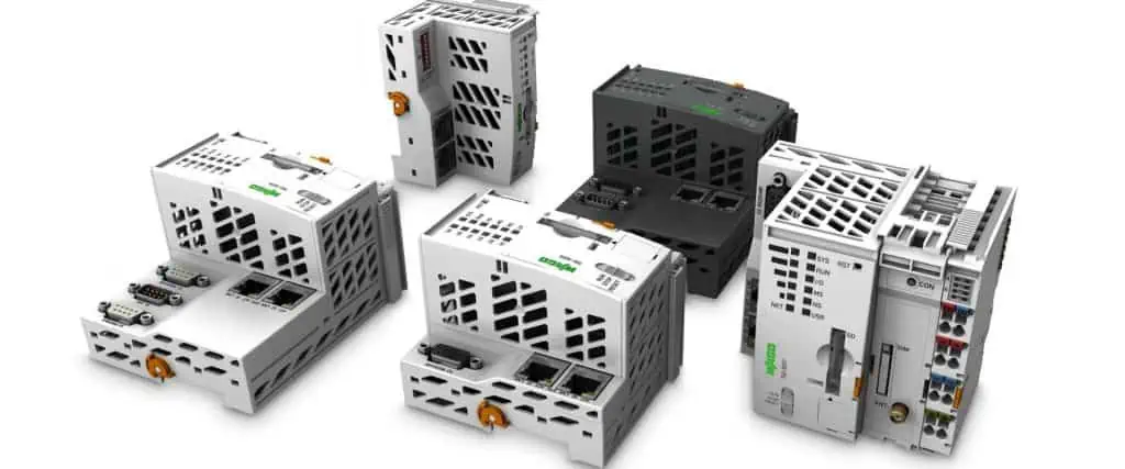
What are the PLC Assembly Components?

PCB assembly Bay Area

PLC components can range from tiny devices that fit into the shirt pocket into enormous PLC racks which are used to manage complex systems. Regardless of their size, these parts may be broken down into three main categories.

  • The rack and power source
  • The (I/O) input/output segment and
  • Central processing units

Smaller PLCs sometimes referred to as “bricks,” have been frequently built with set I/O points. PLCs are frequently rack-based modular systems that may accommodate a wide variety of I/O modules which only slide further into rack as well as plug in.

All the parts are connected by the rack. It may be bought in various sizes to store more modules according to the requirements of the control system. The output and inputs can interface with the Central processing unit through a backplane that is located at the back of the rack. A controlled Dc power is provided by your power supply, which is plugged in the rack.

A PLC can link to both digital and analog outputs and inputs. The PLC is controlled by a unique user program which is contained in the CPU. The processor takes charge of carrying out the required calculations as well as data processing; takes inputs and operates a variety of output devices, such as lights, motors, pumps, relays, etc. The best way to automate electromechanical industrial processes is to employ PLC devices, for example for controlling machinery within assembly lines in factories, amusement rides, and lighting fixtures.

What are the Reasons for the Popularity of the PLC?

FULL PCB MANUFACTURING Quote

You might be asking why the PLC assembly is becoming more and more popular right now. People are choosing PLC PCB instead of embedded systems. PLCs cost a lot of money, but they also provide a lot of benefits. The benefits listed below justify the PLCs’ price tag. You won’t look back on the choice of implementing PLC as your manufacturer.

Manufacturing can be automated and controlled

PLC can be very useful when you’re engaged in a task that calls for hundreds of items. Several tasks are automatable because it connects to the remainder of a machine using both output and input modules. Switches and sensors can both be used as inputs. Users could alter either the output or the input to suit their needs. They simplified interference by humans and machines. Real-time PLC assembly interaction is practical.

It saves room and is portable because to Compact PLC’s smaller size. They are more heat-resistant and have no impact on productivity. They can process commands and store data thanks to their excellent memory. in order for them to interface with systems and computers. Because they are small and efficient with space, a single PLC assembly may easily control numerous units. They do away with the requirement for different systems for all machines and equipment.

Troubleshooting is easy

Rectifications are seldom simple. It takes time to find a flaw sometimes. Rewiring the panels can occasionally be difficult. With the PLC control, every modification to the design of the circuit or execution order only requires retyping of the logic. In PLC, faults may be quickly and affordably fixed. I wonโ€™t waste any of my time for or on it. With plc, troubleshooting is very simple. The issues are also indicated by LED lights located at the front. Because of this, the majority of manufacturers are switching to these PLC assemblies.

An excellent support system and network

PLCs are produced by an established business. The majority of PLC delivery businesses offer excellent technical assistance. They stand ready to assist in the event of every inconvenience.

It includes certificates

There’s a rigid requirement whereby PLC should be approved by regulatory organizations in particular industrial applications. The branded PLCs frequently included certifications such as the CE. Although it might cost more, certified PLC can provide you a number of advantages.

It is Trustworthy

Choose PLC whenever your applications or proposed products would function in a challenging electrical environment. PLC is heat-resistant. They promise you trustworthy goods.

PLCs are very adaptable.

PLC IoT
PLC IoT

They are perfect due to their adaptability and flexibility. The control system only requires a command and set of instructions that change its behavior. The programmable device is a PLC.

You are not required to adjust the electrical system linked to it to change how it behaves; you can just change the commands. It’s a manufacturer’s primary choice because of this. This PLC program can now be modified or deleted whenever you want. PLC is capable of simultaneous communication with many controllers.

Simple Communications

An additional aspect is simple communication. Files or data can be transferred from the PLC into other different computer systems with ease. To carry out control and monitoring applications, PLC can interface with several controllers at once. To interface with the other systems, PLC has a variety of ports as well as communication protocols. You can get this capability from other conventional microcontroller PCBs.

Greater Responsiveness

Real-time response times are quicker with PLC. Within seconds, each logic modifies the output or input status. The function is executed and the inputs are read in milliseconds. If PLC is connected to the other computers, scan times are quicker. Many people tell lies while checking the scan or response times before making a purchase.

Application Fields of the PLC Assembly

In industrialized nations, PLCs are employed in the chemical, automotive, steel, and electrical industries. Given the technological advancement in all of these areas, as well as its application and functionality, the PLC’s range of use expands considerably. PLCs have a lot of uses in various sectors where they manage several manufacturing as well as quality management processes, for example: the glass, paper, cement, food and beverage packaging, automotive, machine tool, and robotics sectors; and the plastics and rubber industries.

PLC Assembly Use in the Glass Industry

Implementing PLC assembly in Manufacturing has been on since 1980; these are utilized in every method and workshop to regulate the ratio of the material, process flat glassware, etc. Also, this is employed for both positional and digital quality controls. The device’s use gives digital amount control and significantly boosts the industry’s control system’s flexibility and dependability.

Using PLC in the Cement Industry

PLCs are used in this business to operate coal kilns, shaft kilns, and ball mills. They accurately record the value of the process variables as they are mixed in the kiln, guaranteeing the highest quality of result. Several cement factories use individual PLC assembly to control the auxiliary duties including water treatment, lab automation, etc. as part of distributed control.

PLC Assembly Use in the Steel Industry

The quenching temperature as well as tempering temperature, the cooling rate during the actual process of production, as well as many other parameters are controlled and adjusted by a PLC assembly control system. High strength lines for steel production benefit tremendously from the effective implementation of the PLC control systems since it increases product quality as well as output, stabilizes production lines, provides control mechanisms flexible and precise, and reduces production costs significantly.

In the Beverage and Food Sector

Machines are used in the beverage and food industries to fill bottles, automatically separate materials, and direct materials in order to overcome the drawbacks of the manual filling phase. Throughout this industry, all repetitive and sequential operations are often done making use of the PLC assembly.

Using PLCs  food industry’s assembly line has boosted production’s speed, precision, and efficiency while lowering labor costs, operating expenses, packing time, as well as danger of hazards.

Systems for Automatic retrieval and storage

Better inventory management, more space for storage and inventory, and quicker and more efficient material handling are all benefits of automated retrieval and storage systems. Sending of signals out from PLC towards the appropriate devices has replaced all the manual processes in warehouses. A PLC-controlled mobile elevator-conveyor configuration successfully automates the entire material handling processes in warehouses. PLC controls warehouse stacker cranes operations very effectively. Warehouse Management is effectively automated through PLC integration.

Benefits of PLC Assembly Integration During Manufacturing

In the automotive industry, PLC devices function best as automated controllers because they are most adapted to the tough industrial environments that include humidity, high temperatures, and chemicals, as well as the electromagnetic interference, the power fluctuations, and other factors.

Due to the modular nature of PLC systems, you can combine and match different types of output and input devices that best suits your application. Users can select from a variety of possible interfaces, from the straightforward light-and-switch system into sophisticated graphic interface screens. After deployment, you can quickly alter the PLC’s design and capacity to meet your unique needs.

Compared to hardware appliances, PLC software offers advantages in security and safety. It has more sophisticated security mechanisms and only discloses information to authorized parties. PLCs that run on software can also lower production costs.

Due to their relatively small size and ability to fit almost everywhere, PLCs offer industrial businesses a safer, cleaner, as well as more secure computer solution. PLCs are significantly affordable than every custom software built to serve this very same roles.

These PLCs are supported by thorough manuals, a supply of spare parts, and a reliable support staff. Large facilities and customers who require a reliable platform capable of sustaining itself for twenty years with spare parts that can survive for 30 plus years are the best candidates.

PLCs are made to be simple to use. Operating them doesn’t require any special training, and keeping track of the choices of the control system is easy.

PLC Assembly – The Core of the Production Process

FT1 BGA Assembly

At first, programmable logic controllers were developed to take the place of the relay control system.

Due to the necessity for expert electricians to rewire such relay systems, updating these structures to implement modifications to the procedure was exceedingly expensive and time-consuming and expensive. PLC assembly made it unnecessary to rewire the relay systems physically because it is now possible to accomplish this by changing the software. As a result, the PLC’s software evolved into the manufacturing process’s brain.

PLCs provide the perfect balance between exceptional performance and reduced costs, a hard-to-find combination. These robust systems withstand the demands of industrial plants and shipping hubs without sacrificing the effectiveness of operations or the accuracy of data collecting & computing.

Many people, things, and pieces of machinery on a shop floor provide a wide variety of data, the majority of which are crucial for managing the business. The PLCs do not keep the data; instead, they gather data and provide real-time accessibility to data about the entire plant.

Conclusion

The management receives highly helpful business insights from the PLC systems’ real-time and current information, which is transformed into detailed reports about production, manpower usage, machine utility, etc.

By combining the ERP system and the PLC assembly system, information would become more transparent and visible, giving management of the business the chance to make better, more informed choices. This will guarantee that your company uses processes and technology effectively to be competitive in the market today.

Harnessing the Power of Arm IOT for Maximum Efficiency

arm iot

The Business, Innovation, and Unification Force that is Arm, which is The cause of the IoT Revolution.

In accordance with a McKinsey report, IoT is poised to transform the globe. It may create $12.6 trillion in worldwide economic value over the next ten years. The ability of numerous devices to capture and analyze enormous new amounts of data autonomously will improve both digital and human decision-making, resolving complicated issues. It includes the effects of climate change, the deterioration of urban infrastructure, supply chain issues, and access to healthcare.

With partners exporting approximately 29B Arm-based tiny chips annually, Arm powers the Internet of Things. Cortex-M series processors, which also are intended for Internet-of-things and incorporated applications, are used by about 70% of such devices because of Arm’s massive computing footprint and the size of the community that develops software. It also has an ecosystem that collaborates around key IoT standards. It is an endpoint-to-cloud solution that can be deployed securely and delivered at scale without experiencing any hiccups.

YouTube video

IoT is already in its future. An Arm-based future.

Arm IOT Embrace Standards To Accelerate Opportunities For The IoT

arm chip
arm chip

The 1.0 Matter protocol and certification procedure have now been issued by the Connectivity Standards Alliance, for which this Arm company has worked for many years. In order to make sure that the ecosystem becomes prepared to assist OEMs and some other product manufacturers in creating these devices, Arm is closely collaborating with companies like Alliance. As part of this effort, Arm is looking into how to integrate Arm Virtual Hardware into the primary CI flow pattern of the Particulate CI or CD infrastructure.

To fully realize the promise of IoT, developers may take advantage of a streamlined development experience by integrating Arm’s core technology with protocols like Matter.

Arm IOT Launches New Processors

Arm Holdings unveiled two new portals to speed up the creation of IoT-based devices, along with its most recent microcontroller architecture to enable high-performance processing at the border.

The Cortex-M85 operates much better than the remainder of the Cortex-M family, which is typically utilized in compact, low-power gadgets such as smartwatches. It is intended to enhance voice recognition capabilities on cutting-edge technologies, such as drones and smart home gadgets.

The IoT is driven by developers, yet there is a constant need for better security, faster performance, and simpler development processes, according to Mohamed Awad, vice chairman of Internet-Of-Thing and Embedded of Arm.

The Cortex-M85 serves as a component of the six-month-old Arm Complete Solutions for Internet – of – things initiative. It is made up of pre-incorporated subsystem layouts that provide a better turnkey approach and lessen the amount of effort required for chip manufacturers to launch their concepts.

The initiative also includes machine learning algorithms and technologies to streamline development and speed up product design, as well as the Arm-Virtual-Hardware cloud-based for evaluating Arm-based products without having numerous variants of actual silicon.

Corstone, a set of pre-incorporated designs that integrates core designs of Arm’s CPU with additional Internet protocol building blocks enabling quick creation and assembly of vertical CPU ideas, is at the heart of the Arm Total Solutions for Internet of Things program.

Arm introduced the Corstone-310 targeting voice-recognition software, and the Corstone-1000 targeting cloud-native network edge devices, as two additional Corstone models for devices with greater performance requirements.

Arm’s Complete Solutions for Voice Recognition includes Corstone-310. It is aimed at appliances that might all employ voice control, including smart speakers, drones, factory robots, and thermostats; the Cortex-M85 processor is used in the Corstone-310 architecture.

Complete Solution for Cloud Native Edge Devices is the name Arm has given to the Corstone-1000, which is a more expensive model. The Corstone-1000 is designed for applications and services that operate on a complete Operating system like Linux and require high-efficiency hardware.

Corstone-1000 built surrounds the Cortex-A architecture because it performs significantly better than Cortex-M. The SystemReady certification process of Arm, which the Corstone-1000 is just a component of, guarantees that perhaps the CPU, as well as its subsystems are completely integrated and functional straight off the box. Moreover, Cortex-1000 is compatible with Arm’s Project Cassini, one that aims to make it easier for programmers to create apps for Cortex-A-based processors that are cloud-native.

Arm IOT for Broader CPU-Simulation Support

FULL PCB MANUFACTURING Quote

To reduce costs, CPU analysis is nearly often performed in simulators prior to actually building test silicon. Arm offers simulators through its Arm Virtual Hardware program.

Without the need for real physical hardware, AVH provides testing platforms for engineers to assess integrated and IoT software across the whole software design process. In order to minimize or lessen the complication of constructing and managing board farms, several modeling solutions are available.

Arm now supports seven Cortex-M processors and the two newest Corstone subsystem architectures. Independent software manufacturers and providers of cloud services will be able to test software against the Cortex-M series as a result.

In addition to developers of the Raspberry Pi, Arm has broadened the offering and included Arm-based devices from alliance partners, including ST Microelectronics and NXP Semiconductors.

Arm IOT Architecture Makes Sense For IIoT Devices

The Industrial IoT or IIoT is anticipatable to grow rapidly during the following eight years.

The IIoT industry will expand at quite a 21% CAGR during 2020 – 2028, as per Quince Industry Analysis, driven by improvements in manufacturing technologies, Industry 4.0, as well as the spread of IoT devices. The current problem is utilizing the Industrial IoT to its utmost capacity to propel future company models.

To achieve so, we require ARM architecture, which will enable us to deploy and control end gadgets in the most effective way possible. In this article, we define ARM architecture and provide the three top justifications for industrial companies using it for IIoT devices.

What Is Arm IOT Architecture?

“ARM” typically refers to an “Advanced RISC Machine” in technical terms. It is a kind of RISC architecture that is gaining more and more important in the contemporary setting.

What Is RISC?

RISC architecture generally seems to be frequently faster and much simpler than CISC design. RISC architecture is important in the latest Industry 4.0, where effective data collection, transmission at the level, and processing are crucial. Whereas CISC architecture, which also contains the x86 architecture, is often appraisable for its durability and adaptability. RISC architecture also has a significant role to play. 

Because RISC architecture uses fewer transistors, it is less expensive and uses less power. Moreover, it uses a smaller instruction code and set base to run at a faster rate with less heat generated. Moreover, RISC architecture served as the basis for ARM. It was first created by Acorn Computing at the end of the 1980s.

Who Makes Arm IOT Microprocessors?

through-hole assembly process

Arm Enterprises, Inc. currently develops and licenses the ARM architecture. Interesting business practices underlie Arm. Arm doesn’t really produce any actual CPUs, in contrast to chip manufacturers.

Arm has a distinctive strategy. They own the property and licensed the fundamental ARM architecture rather than producing specialized chipsets with the ARM architecture.

Because of this, there is a significant market for engineers who want to construct highly specialized products using ARM architecture. Nowadays, several of the biggest names in technology license ARM architecture, which includes: Apple, Intel, Huawei, Microsoft, Samsung, Qualcomm, NXP Semiconductors, and Texas Instruments.

Why Does Arm IOT Matter?

Because it implies that Industrial IoT engineers have the freedom to produce what they want for the unique IIoT applications of their firm, it limits an IoT creator to designing non-embedded peripherals surrounding chips if they select a CPU from, let’s say, Intel.

Yet, by possessing the ARM architectural license, IIoT developers may create distinctive Systems-on-Modules or SoM and Systems-on-Chip. Alternatively, companies may use ARM architectures to directly construct finished products on any CPUs and peripherals manufacturers like.

Such a strategy can eliminate the majority of obstacles to IIoT transition at a specific time when flexibility and customization are essential. The broad use of ARM suggests that it is efficient and valuable for important IoT projects.

Reasons Developers Choose ARM For IIoT?

The Industrial IoT benefits greatly from ARM architecture, as seen by the large number of leading IoT device makers that license it. Although there are numerous benefits to using ARM, few of them are in regard to developing IIoT devices:

  1. Less consumption of Power
  2. Embedded Components
  3. A worldwide Community Support

Low Power Consumption

Apa Itu IoT

Power is a valuable resource that might be scarce in industrial settings. Have a look at some of the isolated oil fields in the Golfo de Mexico.

It may be extremely expensive to deliver electricity to this remote equipment and to keep it running. Devices must be capable of functioning outside of intermittent or nonexistent power infrastructure for Industrial IoT systems to be commercially viable. Our Industrial IoT devices must digitize, sense, and communicate massive amounts of data and information without consuming all of the available energy.

When wireless Industrial IoT devices are available in the picture, it becomes more difficult to achieve this end state. Since wireless networking often consumes a lot of power. Although certain low-power connections can solve this issue, doing so usually comes at the expense of throughput.

Industrial firms cannot cope with such compromise while deploying the IIoT. Devices need to have the capacity to sustain wireless connection and throughput while remaining online for a prolonged period of time. To transmit the information at any particular time. They must use as little power as they can. Also, if processors consume an excessive amount of the transmit power, there will be less power available for data processing.

We require Industrial IoT devices to function without external energy sources in specific environments. What if, for instance, you have an interest in maintaining an eye on a generatorโ€”an actual power sourceโ€”in real time? Your destination node couldn’t monitor the generator’s functionality or uptime while using that generator source for electricity. Then how could you monitor a distant pipeline without an existing power source?

It is obvious that installing a regional power grid just for asset monitoring would not make sense. Harvesting renewable energy clearly has a role in this, but costs continue to be high, and efficacy may be constrained.

It would simply not be possible to monitor these assets effectively without some power-efficient Industrial IoT devices.

We are able to operate Industrial IoT devices on separate power sources thanks to ARM architecture. Think about a contemporary smartphone. Smartphones made use of the ARM architecture to save computing power and extend screen duration and wireless transmission.

Under typical usage, the majority of smartphones have a battery life of one to two days, largely because LCD panels and streaming internet access consume a lot of power. Just a few days’ worths of battery capacity are insufficient for Industrial IoT devices.

IIoT gadgets must live a lot longer. For instance, the 4G LTE wireless WellAware CONNECT gadget may operate for many years just on 3 D-cell rechargeable batteries. This is the feature that makes ARM particularly appealing for Industrial IoT applications in outlying areas. We can depend on processors built by ARM to utilize less power. Especially when we restrict data flows, keeping it available for other uses.

Arm IOT Processors Come Pre-Packed With Great Peripherals

Smart Manufacturing IoT

There are countless development options available because ARM seems to be a licensed and certified architecture rather than hardware that must be incorporated.

You’ve probably heard of Raspberry Pi or Arduino as an electronic maker geek. These approaches offer incredibly adaptable ARM-based microchips that let users easily manage peripherals and sensors.

Developers may leverage ARM in a comparable pattern to control IIoT sensor data inputs. Also, process multiple data kinds, and activate different gadgets or outputs. Developers of IIoT devices have access to built-in parts and peripherals that are readily available thanks to ARM.

As an illustration, the Nordic nRF52840 SoC drives the most recent WellAware Integrate devices. It has WiFi, Bluetooth 5, and Embedded security features. The features include key-hashed secure communication, AES-128 encryption, and randomly generated number generation. They compile with NIST standards, Temperature sensing, Serial UART, and IoT sensor incorporation.

With the help of ARM, almost all these features and parts are available in one SoC. It enables WellAware programmers to develop amazing end products with a great deal less effort.

The ARM platform’s architecture makes it possible for it to handle a wide range of technologies. It includes IoT applications, smartphones, laptops, and servers. We can leverage ARM to provide highly technical sensor data collecting and transfer all on one chip for the IIoT.

In order to quickly create novel hardware ideas for particular industrial issues, the development team relies on ARM. We have already developed several types of industrial Input and Output around basic ARM architecture design, from intelligent air filtration systems to chemical pumping control systems and monitoring for tank level. In addition to that, we have access to every system on one SoC. Our code is typically effective and standard.

Arm IOT with Vibrant Global Support Community

The community comes last and is arguably the most crucial. A vibrant, active worldwide developer community supports the development of ARM architecture. This is by far the most appealing aspect of ARM architecture as well as the embedded chipsets it supports for many people.

Since about 2019, there have been more than 130 billion ARM-manufactured processors in use worldwide. They are making it the most popular Instruction Set Architecture.

One understands and knows the ARM very well. Similar to how SoCs provide integrated hardware elements, we also have hundreds, if not billions, of libraries at our fingertips that facilitate IIoT development.

Developers can use the prior effort and experience of others in order to gain pre-built program functionalities. It’s not necessary for us to create the latest ML designs from the start, design WiFi packet formats, execute MQTT protocols, or compose our custom Modbus instructions. Libraries that a number of the global’s best developers frequently contribute to already have these features and more.

In actuality, the non-differentiating solution sets and libraries are the main emphasis of Linaro. It is an ARM innovation community by several of the top important ARM licensees. Developers use Linaro to solve common issues, freeing them of their spare time to concentrate on innovation or difference.

Use Arm IOT To Set Organization Up For Long-Term Success

The IIoT won’t be disappearing anytime soon. The architecture by ARM is the greatest option moving forward for companies. The ones who are looking to benefit from real-time tracking and smart gadgets for industrial uses.

Everything you Need to know about GE IoT – Lessons to Learn

ge iot

General Electric Company has spent more than 120 years specializing in the production of large industrial machineries such as jet engines, power turbines, and imaging devices. The software would’ve been GE’s future growth engine. Former GE CEO Jeffrey Immelt decided to consolidate the company’s digital business units into a different division. This signaled a break from the company’s core business as well as a modernization of the corporation.

Predix, a GE software product suite designed to act as an OS for heavy industrialization, was at the heart of this plan. The goal was to use machine learning to optimize the upkeep and use of production plants by gathering data from the “internet of things” in the industry.

YouTube video

To keep an eye on physical assets, GE has a number of apps. As an illustration, turbine sensors may provide data on power output, wind speed, and motor maintenance conditions. GE may use algorithms to detect breakdowns and improve maintenance chores for certain components. Or realign a whole system and lower costs by centralizing data and developing virtual models. Or, you can say, “digital twins” of gear. Predix held enormous significance to the business both internally and internationally because it would enable GE to better utilize its own assets and market Predix to industrial clients as a centralized database for process optimization.

Top Benefits oF GE IoT

esp iot PCB
esp iot PCB
  • The relaxed connection between assets and faces, as well as between the edge and the cloud. Support for OT standards, challenging work situations, and two-way cloud/facet communications.
  • The platform’s services work together. Platform services and infrastructure such as automation and service orchestration. For owners and creators of applications, this provides safeguards.
  • Control over statistics supports scalable, adaptable industrial use cases. Ingestion, tag mapping, and filtering across several data types make up the statistics pipeline.
  • Each platform layer is securable with defense-in-depth strategies for security. It decreases the program risks with the aid of authentication, user management, and other services.

GE IoT Predix Partnered with Microsoft Azure

Azure is indeed a cloud-based computing system and supporting infrastructure from Microsoft. It provides IaaS, PaaS, and many tools for system development. Internet-of-things GE Predix makes use of several other features, such as modern natural language processing, AI, and enhanced information visualization.

Microsoft intends to eventually connect Predix, such as its Microsoft Azure IoT suite and Cortana Intelligence package, as well as its business applications. Azure could also allow users to create packages using Predix statistics. 

Predix Developer Kits

Builders just need to provide an IP address, Ethernet connection, power source, and light coding to start data gathering.

The kit automatically makes the required connection, registers with the crucial Predix system, and begins transmitting environmental data from sensors. Users pay for hardware or software output by GE Digital on behalf of the user.

The cumbersome and uneasy simulation and evaluation environment assembly are replaceable by the Predix Development Kit. In other scenarios, developers frequently employ a broad range of software tools and specific setups for each link.

Also, they program each device’s monitoring, which occasionally takes hours. The kit drastically cuts down on the amount of time needed to do these tasks, from hours mostly to efficient minutes.

Growth Challenges

FULL PCB MANUFACTURING Quote

When the system’s introduction time, Immelt says, “Predix would propel GE toward being the preeminent software firm by the year 2020.” Rather less tech-savvy clients would be able to use Predix to design physical systems using the “software equal of Lego bricks” in an ecological system supported by GE’s algorithms that use machine learning for optimization. The corporation employed around 1500 experts and invested $4 billion in exploration in 2016, spending in line with this aim. Yet, P&L accountability limits GE Digital since Predix’s development was so expensive.

Developing specific software for production processes, gear controls, and tracking that indicated relatively brief digital initiatives as compared to fresh, flexible systems for machine learning and modeling that would bring relatively long-term worth to GE as well as its clients. The company’s digital arm was able to become profitable. These platforms would later become consulting centers for industrial firms.

2017 saw a shift in the company’s Predix strategy under the leadership of newly appointed CEO John Flannery, who slashed the funding for the products and insisted on a more “targeted approach” before hiring an investment company to find customers for GE’s digi-division. Predix’s future is still in doubt, and the most recent CEO of GE, Larry Culp, has recently kept on setting up asset sales only as means of obtaining funds.

Future Direction

Machine learning has a distinct value proposition in asset-intensive sectors. It is possible to optimize energy or transportation networks to increase load balance and utilization. While component failures may otherwise lead to system outages, models that identify regular maintenance, even for the little component in some kind of a single piece of machinery, provide the opportunity to save thousands. So, it might be a misunderstanding for GE company to completely give up on Predix, although the product does require focus. Predix must be improved for internal usage in the near future to enhance the efficiency of the industry’s physical processes, as there are some signs that GE subsidiaries have difficulties using Predix successfully. Predix should be capable of generating “digital twins” across every one of GE’s internal asset classes thanks to R&D investment.

Moreover, GE has to keep establishing alliances with corporate clients in order to develop its infrastructure and model processes beyond its primary business sectors. If GE is able to utilize those efforts to generalize or enhance its current models, working with customers to develop special analytics apps is a great intermediate plan. Predix must be developed into a fully adaptable AI engine capable of being fitted to any industrialized society for optimization as the company’s long-term objective.

In the IoT industrial market, there are many rivals and enthusiastic newcomers. The digital business of GE has threats from established rivals such as Rockwell Automation, industry leaders such as Amazon and Google, and start-ups including C3 IoT. In certain aspects, rivals are better equipped to manage enormous volumes of information from industrial operations and create generalizable algorithms for enhancing industrial operations. Also, GE’s core skill of creating and producing items of physical equipment is now at least another step being removed from the software. A few concerns are brought up by this collection of circumstances. Should GE give up on Predix and give in to rivals in this market? Focusing on key competencies would be beneficial for the business, but does ML in the IoT industry really promise a better future for the coming GE?

Lesson To Know From The Failure Of GE IoT

Smart Manufacturing IoT

Recently, GE revealed it had been selling off its business in digital assets, which is largely attributable to the failure of its Predix IoT Industrial platform. By 2020, GE projects to sell $15 billion worth of software, with Predix expecting to generate half of those sales. Predix has certainly not begun taking off as anticipated.

1. Deep Pocket Do not Guarantee Success. 

Being a significant manufacturer with a loyal client base does not automatically translate to success in creating your own platform. GE’s substantial financial resources and broad client base did not ensure Predix’s success.

2. Supporting Too Many Verticals

Building a software place that functions across several industries is challenging. With a dispersed approach, GE constructed an all-purpose infrastructure for the larger industrial world in an effort to provide everything to anyone.

3. Wrong Partner Ecosystem

Parthasarthi V asserts that in order to succeed, your offering must allow your partners to move uptown. If you look at the GE partners’ business models, not a single of those partners had the chance to use Predix to grow up-market. GE made a poor partner ecosystem choice. There are no financial rewards for the partners to use Predix and advance in the market. The current partners would only invest so much, and while they did educate their staff and develop Predix apps, it wasn’t sufficient for Predix. Because its competitors could not go faster, GE was unable to run quickly.

4. Building Their Own Cloud Data Center

By building its very own Predix cloud-based data hub to manage the data generated by industrial assets, GE made a strategic error. It took quite some time For GE to grasp the fact. They really were up against industry titans, including Amazon, Google, and Microsoft, when it came to cloud computing.

GE IoT Platform Must Be Developer-Friendly

embedded iot

The Predix platform seems to be notorious for being unfriendly to developers. Future-oriented monetization options should be offered by an IoT network. It needs to be attending to the requirements of expert developers. A solid platform makes developer material accurate, findable, and readable. Developers also require informed community support.

5. Not Transitioning To Service Mindset

The CEO and research head, Dima Tokar, at IoT researcher MachNation, claims that GE was defeated to make the switch from a corporation. It is mostly focused on products to one that is primarily focused on services. According to him, the transition calls for not just an advancement in human assets. But also one in corporate culture, the way sales incentives are structured, and many other areas.

6. Edge-To-Cloud Accessibility 

Predix Essentials works as a Saas service. It enables businesses to connect to various monitor operations and data sources. It also uses edge-to-cloud data analytics. This reduces the time to benefit operational work teams wanting to cut waste, save costs, and improve performance. Predix Essentials was created in collaboration with a number of customers, including semiconductor manufacturer Intel. They can be used as a starting point by industrial businesses who want to use cloud-based IoT Industrial technologies. It offers the visualization, connectivity, and analysis features necessary for a journey toward digital transformation. It provides irrespective of the vertical sector and application maturity.

Predix Essentials, which is appropriate for all kinds of industrial businesses, serves as the core of GE Digital’s OPM and APM application suites. It offers functionality and bridges the software profile. It offers by integrating on-premises information from its MES and Historian options.

7. Maintenance Strategies

Industrial-IoT-Devices

Asset Answers would be a competitive tool that assists users in importing and analyzing information. It’s to comprehend how their resource upkeep stacks up against that of other businesses in a related industry. Or compared to their actual performance across many sites.

Customers may better allocate their resources for upgrading maintenance regimens or features and give a path to solutions. Such as APM, to monitor and optimize assets throughout the whole company with the use of this information. There are several sectors that Asset Answers provides accessibility for, including natural gas and oil, chemicals, and power generation.

8. Improving Operator Mobility

With its Webspace 6.0 online and mobility service, GE’s CIMPLICITY and iFIX HMI/SCADA program may now be seen and controlled on a variety of devices, which includes smartwatches, tablets, smartphones, and desktop computers.

Webspace 6.0 contributes to enhancing how operators accept and act on operational insights, no matter where they are. Whether it’s on the ground, on the production floor, or at their desk, by offering encryption as well as the latest zero-install HTML5 customer, this gives users more adaptability to make better choices and share knowledge irrespective of location. Webspace 6.0 enhances agility through real-time control and visualization. It helps to promote information exchange across teams and speeds up the operation of making the right decisions.

Top 10 Electronic Engineering Companies – Unlocking the Potential

Just take a second and imagine a world without technology and electronics. From our homes’ recreational spaces to the familiar surroundings of our businesses, electronics play a key role. In short, without electronics, the digital world that has taken over the globe ever since the 1990s cannot even begin.

 If there were no electronic manufacturing business, electronic gadgets would not exist. These businesses possess the technical know-how, assets, and tools necessary to bring electronic devices to market. Understanding the many electronic firms that are present in Europe is therefore essential, particularly if you wish to buy the latest electronic equipment for use at work or at home. Then what brings the list of top 10 European manufacturers of electronic goods, and how would you choose one to meet your electrical needs?

Choose the Best Electronic Engineering Companies

2.4 ghz pcb antenna design

Selecting a source of electronic solutions for your gadgets in Europe may prove to be a difficult process. There are many different electronic manufacturers, and they all charge differently for their offerings. Apart from pricing, different electrical manufacturers will operate in different ways generally. It is, therefore, crucial to making the appropriate choice because it is simple to choose the incorrect electronic manufacturing firm. So, how should the selection procedure is carried out? Consider some things such as:

YouTube video
  • Ratings from electronic manufacturers. With the advent of the internet and personal computers, it is now possible to rate the quality of electrical manufacturers. Ratings frequently play a crucial function in determining the caliber of a manufacturer’s services or goods. For this reason, consider the ratings of each manufacturer and choose which one performs best, particularly in terms of their services, goods, and cost.
  • Reviews. There is presently no other instrument that helps future customers decide on a product or service supplier than the reviews. These are already accessible from prior customers. An effective way to assess an electronic manufacturer’s strengths and shortcomings and determine whether they are a good fit for your needs in terms of electronic manufacturing is to read internet reviews about them.
  • Peer referrals, such as from friends, family, and colleagues, may be very important. It offers yet another fantastic method for finding the electronic production businesses that best meet your requirements. As a result, seeking guidance from trusted & dependable sources such as friends, colleagues, families, and peers might help you choose the perfect EMC.

Attributes to Determine the Best Electronic Engineering Companies

FULL PCB MANUFACTURING Quote

Electronic manufacturing businesses frequently provide their assistance, and these comprise design, production, assembly, and screening of electrical parts, such as PCBs, to customers. Hence, it becomes crucial to ascertain whether the manufacturer of electronics has the following traits whenever you decide to choose such a firm. Consider some things such as:

ยท An updated website

Companies that manufacture electronics should have legitimate, up-to-date corporate websites that provide information about their history, capabilities, and services provided. You may assess the EMC’s technical capability, equipment, and resources to satisfy your demands for producing electronic devices using a website such as this. Before deciding on a manufacturer, you may also utilize the information supplied to research and examine rivals. Before contacting the manufacturer personally or online, you may learn a lot about them through the website’s presentation. Also, you may always interact with them and clarify any points that are confusing to you.

ยท The credentials of the company

The ideal electronic producer for you needs to possess the relevant licenses required for the particular creator of your item. On their authentic, official website, a fast background search can always provide results. It turns into a key factor in assessing the company’s ability to produce high-quality electrical goods. You must seek elsewhere if a firm holds all the licenses and certifications it needs but is unable to effectively produce your electrical device.

  • The ideal electrical producer for you must own all the tools necessary for your device’s creation. In order to produce high-quality and effective electronic devices, ascertain this particular aspect to comprehend whether the producer can manage your device’s from-the-ground-up design requirements or can adjust certain aspects of electronic component specifications. Maybe all you want is a thorough assessment of your requirements in order to receive unbiased and knowledgeable advice prior to the production process.

ยท Equipment and technology

In order to successfully produce an electronic device, the manufacturer must possess the technical expertise and have access to the necessary tools and technologies. Hence, before choosing a manufacturer to fulfill your demands for the creation of electrical devices, ascertain their capacity in this area. The majority of leading electronic manufacturers have access to knowledge and/or technology for a variety of device production requirements.

Top 10 Electronic Manufacturing Company In Europe

Electronics panel board manufacturers

1. Integrated Micro-Electronics, Czech Republic

In the Czech Republic, Temonรก, a reputable electronic manufacturing business, was established in 1991. It operates 4 SMT lines that produce, develop, and sell electronic components for a variety of sectors.

Due to their superior production capabilities, the multi-ISO accredited electronic manufacturer provides you with high-quality and prompt electronic goods. The business employs over 20,000 competent workers and uses the most up-to-date tools and technology to produce high-quality electrical gadgets.

Company Features

There are many amazing features, such as:

  • focuses on Printed Circuit Board mounting for the automotive and industrial sectors
  • focuses on electronic orders of a medium scale
  • offering complete, customized technological solutions
  • Such as markets for renewable energy, industrial production, and vehicles

Company Services

It offers services such as:

  • production of electronic goods
  • designing, creating, and selling electronic components

2. BMK Group, Germany

In 1994, a German firm that manufactures electrical devices was created in Augsburg. It explores electronic product creation, production, and post-production. The well-regarded electronic company demonstrates many certifications and places a strong emphasis on developing long-lasting connections with customers, stable supply partnerships, regulated organization, and manufacturing procedures. Together with automated defect data collecting, it also explores the optimization of design through design and development cooperation.

Company Features

There are many amazing features, such as:

  • Together with embedded security, electronic development also includes electronic layout and development.
  • manufactures, such as the production of gadgets and prototypes
  • Electronic repairs are part of electronic services.

Company Services

It offers services such as:

  • Manufacturing Of Electronics
  • Services of Manufacturing 
  • Repairing

3. Matra Electronique, France

The acclaimed electronic manufacturing business was founded in 1981 and belonged to the MBDA Group. To give you high-quality and efficient electronic equipment or gadgets, it digs into the production and Layout of highly technical electronic products.

The business is based in France of Lacroix-Saint-Ouen and produces goods for the natural gas, oil, aerospace, defense, and medical industries.

Company Features

There are many amazing features, such as:

  • 100% MBDA affiliate 
  •  Engages in the design and production of electronics
  • targets the aerospace, health, natural gas and oil, and defense and security industries

Company Services

It offers services such as:

  • The layout of electronic machinery and apparatus
  • the production of electrical equipment and gadgets

4. Jabil Circuit, Hungary

An amazing source of electronics fabrication solutions in Europe is a highly regarded electronic manufacturing firm. It was founded in 2000, and Tiszaujvaros, Hungary, serves as its administrative center. The firm is an excellent choice for making sophisticated electrical devices, particularly for the automotive, industrial, storage, communications, and healthcare industries.

The firm develops and assembles high-quality electronic goods for businesses and people using a committed and highly experienced workforce in addition to cutting-edge machinery and technology. In addition, the plant operates round-the-clock and possesses Hungary’s largest production space.

Company Features

There are many amazing features, such as:

  • market with a variety of sectors
  • flexible manufacturing and design skills for electronics
  • a sizable 232,331-square-foot manufacturing area

Company Services

It offers services such as:

  • Advanced Assembly Process
  • Cutting tools
  • Precision Automation
  • Supply Chain
  • Wide range of software, such as mobile, web, IoT, Embedded systems, and Wireless networks
  • Material sciences

5. Tonfunk Group, Germany

PCB Antenna Layout
PCB Antenna Layout

The electronic production company, which was founded in 1990, offers a reliable manufacturing service for electronic modules and devices. This service includes the development of circuit design and layout, 3D analysis, and layout technologies. Additionally, SMT and THT manufacturing, assembly, installation, and production encapsulation and traceability.

The business, which has its headquarters in Germany, Falkenstein, aims to collaborate with you while they create unique electrical equipment for customers.

Company Features

There are many amazing features, such as:

  • production procedures that are organized to follow standards of quality and legal requirements
  • emphasizes combining heritage with innovation
  • focuses on the automotive, communications, medical, sensor, nautical, and security industries
  • 450+ staff members that are qualified

Company Services

It offers services such as:

  • Manufacturing or production processes such as THT, SMT, installation, painting, encapsulation, Traceability, and soldering methods used to produce products 
  • Post-purchase services

6. Leesys, Leipzig, Germany

Founded in 1925, Leesys has sometimes been referred to as the Katek Leipzig GMBH or Leipzig Electronics. The organization is a good choice for your demands regarding electronic devices. It is due to its greater than a century of experience providing superior electronic production services.

The firm, which has its headquarters in Germany, Leipzig, produces excellent, approved electrical gadgets. It serves the telecommunications, healthcare, connected homes, industrial electronics, automotive, and industrial electronics industries.

Company Features

There are many amazing features, such as:

  • markets that span many industries
  • Multi-service supplier for prototyping, manufacturing, and related services
  • Outstanding production capacity 
  • Certified

Company Services

It offers services such as:

  • production of electronic goods
  • electrical product creation and research
  • Production
  • Post-purchase services
  • clearance of customs and logistics
  • Prototyping
  • materials administration

7. Asteelflash, Germany

The company attempts to provide you with high-quality, approved electrical equipment.

The firm, which is based in Germany, Bad Hersfeld, wants to collaborate with customers to manage electronic production and assembly so that you may create high-quality electronic goods. Moreover, it has around 250 trained employees and over 100,000 square feet of production area to ensure high-quality electronics.

Company Features

There are many amazing features, such as:

  • markets that span many industries
  • Features with several uses, such as design, PCB assembly, system integration, etc.
  • Construction of cooperative ties with customers to generate high-quality electronic goods

Company Services

It offers services such as:

  • design assistance
  • management of a lifecycle
  • intangible assets
  • Prototyping
  • Prototyping
  • wide distribution
  • introduction of novel products
  • efficient supply chain

8. Enics, Elva, Estonia

While it dates back to the 1960s, the highly regarded electronic production service firm was created in 2004. By creating, producing, and offering post-production lifespan electronic services, it seeks to meet client demands by offering high-quality electronic service products.

The business, which has its headquarters in Estonia, Elva, focuses mostly on producing electronic goods in addition to supply-chain operations.

Company Features

There are many amazing features, such as:

  • focuses on comprehensive manufacturing operations and the electronic devices supply chain 
  • ODM Products

Company Services

It offers services such as:

  • In addition to after-sales services, product lifespan services include comprehensive engineering and production.
  • Electronic test, and analysis development services, such as DFT, hardware evaluation setup, mechanical and software design, HVT, boundary scanning, etc.
  • Management of supply chains to ensure the delivery of high-quality electrical products while reducing complexity

9. Kitron, Lithuania

Leading Scandinavian provider of electronic product solutions is a highly regarded electronic manufacturing firm. The firm entered Lithuania around 2001 after being founded in 1962. It seeks to increase value chain flexibility, cost-effectiveness, and innovation power.

The authorized EMS Company can supply a variety of electronic goods, from completely completed Circuit Boards to electronic end products. Thanks to its approximately 1800 professional staff and cutting-edge technology. It is situated in Lithuania’s Kaunas.

Company Features

There are many amazing features, such as:

  • multi-sector supply market and target
  • various services for electronic manufacturing
  • competent and devoted crew (over 1800)

Company Services

It offers services such as:

  • Procurement And Sourcing
  • Development
  • Industrialization
  • Product Deployment
  • Maintenance, Redesign, and Repair
  • Field Service
  • Manufacturing
  • AR Manufacturing

10. FlexFlex, Zalaegerszeg, Hungary

The highly regarded EMS Corporation, with headquarters in the city of Zalaegerszeg, Hungary. It provides services to energy, networking, automotive, computer, consumer, enterprise storage, and other industrial sectors. It was founded in 1969 with the intention of providing customers with design and engineering services, PCB assembly, NPI, and CTO/BTO for minimal assembly.

Company Features

There are many amazing features, such as:

  • Manufacturing, engineering, and design services 
  • with over 50 years of expertise

Company Services

It offers services such as:

  • Design
  • Engineering
  • Fabrication
  • Assembly

Conclusion

Electronics serve as carriers for the revolution of digital and are crucial for usage in many different sectors and at home. In order to have electronic gadgets and equipment created swiftly, with high quality, and at the lowest price. You do not just need to choose the right electronic producer in Europe, as well as the best ones.

In addition to important details on finding a fantastic manufacturer outside of the mentioned list, the post has included some of the best European electronic manufacturing businesses. To fulfill your desires for electronic gadgets and equipment, take into consideration the suggestions and the firms mentioned.

The Art of Pads PCB Design: A Step-by-Step Guide

pcb pads

We know you have many things to do, so we will install your new floor quickly. Our experts will explain how different types of flooring can benefit you financially and help you choose the best option.

You might be new to making PCBs, or you might be experienced. Your job might have changed, and you must ensure the PCBs your design is of good quality. You might want to learn the newest ways to design PCBs for electronics. This guide will teach you how to design PCB pads confidently and accurately, whether new or experienced. 

What is the PADS PCB design? 

PADS is software for designing circuit boards made by Mentor Graphics. There are three different versions you can choose from: the Standard plus version, the Standard version & Professional version. 


YouTube video

Key Features of PADS PCB design

PCB Layout in KiCA
PCB Layout in KiCA

ยท Super schematic & layout tools:

PADS PCB has a feature where you can choose and confirm the electronic components you want to use, and it also has different levels of difficulty for drawing the design plan. 

ยท Scalability:

As technology gets more complex, you can add more features to ensure it works well with your design needs.

ยท Component organization: 

PADS PCB makes it easy for users to track the electronic parts they’re using, like the component number and value. The software has a big library of over 11,000 components/elements and devices.

ยท Variant reprocesses 

This feature lets you use the same design plan for multiple practice runs and layouts.

ยท Optimization feature 

This feature can save you up to 30 times more time than regular methods. It helps to reduce the amount of time it takes to make the product and the cost of making it.

ยท Broad electrical rule check:

PADS printed circuit boards have a great feature that checks if your design plan follows all the rules correctly. It includes difficult rules such as Electromagnetic rules. 

ยท Analog simulation: 

PADS PCB has a complex circuit model that you can use to simulate different kinds of circuits, like mixed-signal, equivalent, & technology circuits. 

How to Use the PADS PCB design Layout?

FULL PCB MANUFACTURING Quote

Here are some simple things to do when using a PADS layout.

First, select the electronic parts you want to use on the board, like sockets or capacitors. Then, get the datasheets for those parts and check the imprints, which show you the size and shape of the holes or pads you need to make on the board. 

In reality, the main categories of electronic parts used are. 

  • Capacitors, Ferrite beads, Resistors, and Inductors
  • LEDs, Transistors, FETS, Diodes
  • Headers, Connectors
  •  ICs, BGA ICs
  • Other electronic parts

It’s very important to be extra careful with connectors since they are the simplest electronic part. Also, make sure you have the physical side in your hands to check the number of pins, dimensions, and how it’s oriented. 

ยท Footprint creation

For each electronic part, you need to create a footprint. A footprint/imprint is the physical view of the component, showing where the holes or pads need to be on the board for surface-mounted parts. You can also use the same footprint multiple times on one board.

Most of the time, you will already have the footprints you need. You may need to make a few new footprints for a new design. Make sure to double-check that the footprints in the layout library match the mechanical dimensions of the component, as specified in the datasheet. 

Companies like Texas Instruments provide reference designs that you can use to get their PADS design and export their imprints/footprints. You can use these footprints with little or no changes. 

ยท Schematic View of the Board

Next, you need to make a schematic view of your board. This involves adding various components to the board and connecting them with wires. To create the schematic, you can use Orcad software. However, if you are new to Orcad, you may have to take a tutorial to learn how to use it.

After finishing the schematic, you must create a list of connections (called a netlist) and import it into PADS. With PADS, you can then define the ground & power connections, arrange components, and connect physical wires. It’s important to check for any errors before finalizing the board design.

Once the board design is complete, you must generate some Gerber/artwork files. PCB manufacturers use these files to produce the board according to the design specifications

Color Settings for the PADS PCB design

To make it easier to view your printed circuit board design when using a PADS layout, you should assign different colors to each layer. 

In PADS, the top layer is usually shown in blue, while the bottom layer is shown in red by default. Each layer includes many elements, such as traces, devices & copper foil. It differs from Altium Designer, which uses a different default color scheme.

You can also choose to set different colors for each component in PADS. It will make it easier for you to tell them apart.  

ยท Using the PADS PCB Design Software

You can go to the PADS printed circuit board website and download the new version for free.

To ensure that the board fits properly inside a casing without any damage, it’s important to consider the permissions of components both electrically and mechanically. It would be best to consider the technical aspects during the design process. Make sure that your electronic & mechanical design takes into account the permissions of the components and the physical constraints of the enclosure. It’s important to communicate well between your electronic and mechanical teams to avoid any last-minute changes that can cause delays and extra costs during manufacturing. 

Understanding that the PADS program can create and manage all the necessary content is essential for a strong design foundation. PADS PCB offers a comprehensive design flow from start to finish. It allows you to properly balance rules & limitations to produce top-quality, financially beneficial networks. 

ยท Capturing Schematics for PADS PCB design

A schematic is a picture that shows how the different parts of the design are connected, and it includes information about the parts and rules for how they should be used. You can use the schematic to get information in different formats, such as a list of connections or parts. The schematic is a visual representation of your design that shows how components are connected and their specifications. It provides data in various formats, such as connectivity and a list of components. It helps you input information into simulators & design plots. As a dynamic layout database, it contains component interconnections, characteristics, values & tolerances. 

To create a schematic in PADS, start by going to the PADS start page and clicking the “Create tab.” 

First, choose all the parts you want to use and then adjust their settings. The software gives you an example on the right side of the screen. Also, remember that there are many different tools and options at the top of the tool that can help you create your unique designs. 

Once you’ve drawn your circuit diagram, you can check if it works correctly. To do this, go to the Libraries part and click on Common. Then click on “Central Library Synchronization” to see if there are any problems with the parts of your circuit. If there are issues, they will be marked with yellow warnings.  

The Management of PADS PCB Design Components 

PCB Layout in Chinese PCB Manufactuer

PADS printed circuit board Design makes it easy to get information about any component by using just one spreadsheet. You don’t need to worry/anxious about having too much data or using too many libraries, which can take up a lot of time. Also, PADS printed circuit board Design can work with commercial components & MRP databanks using industry-based ODBC. With this feature, designers working in different locations can easily get important information about components. The tool also makes sure that everyone is using the same updated information. It helps to avoid costly mistakes and problems that could be missed otherwise.     

Don’t forget; you can also use PADS printed circuit board Design/layout component manager differently. If you’re looking for a specific component, enter the search term, and the tool will show you all the components that match it. You can also narrow the search by adding more details, like if the component has a tristate output/result. The software shows how many components meet your search criteria after each search.

To look at and pick an element, you can look at all the components and their details in the component administration spreadsheet. You can also use direct links to access all the information about a component. It will give you a lot of information about each component. Once you’ve picked the components you want, it’s easy to add them to your circuit diagram. 

Adding Generic Components to PADS PCB design Schematic 

If you desire to select a manufacturer to make your printed circuit board, select the parts you need, and the tool will show you all the available PCB manufacturers. It will give you data based on different factors, like how long it will take to get the boards, how much they cost, and how many are in stock. Once you’ve picked a manufacturer, you can match the special parts in your design to the standard parts used in the circuit diagram. 

You can utilize PADS to check if your circuit design is reliable. It makes sure that all the information in your circuit diagram matches the parts that you have in your inventory. Also, the PADS component management tells you which components in your design aren’t printed exclusively. It’ll also automatically fix any mistakes in the properties of the parts.   

You can also use PADS to find a specific reusable design block. It makes it simple to find and use the right design block in other circuit diagrams. 

PADS PCB design Layouts 

It’s important to know that you can use PADS printed circuit board Design’s advanced layout features to quickly and efficiently create complex circuit boards, no matter how complicated the circuit is. With PADS printed circuit board Design, you can easily manage the whole design process, regardless of its complexity. 

You can create your layout faster using PADS PCB Design’s physical design reuse, production preparation, and improved 3D visualization features. By making sure that your schematic & layout match perfectly, PADS will help you finish your project quickly. It means you will have fewer mistakes and have a better quality final product. Another advantage of PADS Standard Plus is its unique options for time-saving design-for-test reviews and fast routing capabilities.

Remember that every version of the PADS printed circuit board Design comes with a PADS layout. However, the PADS advanced version includes a dual-licensed design with advanced characteristics from Xpedition PCB.

With PADS printed circuit board Design, you can see a complete 3D view of your circuit board, including all the parts, pads, solder, traces, mask & other components. This photorealistic view lets you precisely assess your printed circuit boards before you create the final product. Additionally, the 3D view allows you to see the inner layer stack-up of your PCB, giving you the information you need to create custom boards with confidence and skill. 

Finally, you can use PADS PCB Design to estimate the smallest distance between objects to determine how close or far apart they are from each other. You can also add mechanical features like covers and heatsinks to your design and check if they fit properly. 

Designing a new PCB from the beginning involves considering many factors. You have to make many decisions and trade-offs throughout the layout process. It would be best to think about different elements and options at each process step. 

Why Should You Choose PADS PCB design? 

  • PADS PCB design includes a thermal assessment feature that allows you to check the temperature of your PCB and identify any design problems related to temperature. 
    • Power integrity examination: This feature can help you identify problems with how power is distributed in your design, even before you start laying it out. It can also detect issues with voltage drops
    • Multi-Trace HSD: It (High-Speed Design) works well with advanced design features and tasks to reduce the time it takes to complete a design
    • PADS PCB provides a simulation service called AMS Cloud that can give accurate results.

Final Thoughts

 PADS printed circuit board design provides solutions for various technical design issues and provides a supportive environment. It helps you to complete demanding layout schedules, making you stand out from others. With PADS printed circuit board, you have the appropriate software and tools to meet your current & future design needs. Remember that designing a PCB requires making design decisions continuously. 

RayPCB is a company that makes PCBs and has much experience in this field. They can make of PCB that you need. If you have your circuit board layout ready, you can get a free quote from them to start manufacturing your PCB. 

How to Utilize Smart Buildings (IOT) for Maximum Efficiency?

smart buildings iot

If you manage a building, you may have heard of “smart buildings.” These are buildings that have advanced technology to help you control things like temperature and energy use. Smart buildings give you more power over the premises’ functions. 

When you have more control over your building’s environment and operations, you can experience many benefits. For example, you can remove people from an area if the air quality worsens, or you can save lots of money on electricity by controlling your HVAC system more efficiently. The outcomes of making smart building decisions are actual and very good for the people inside, your business earnings, and the planet. That’s why 70 percent of companies plan to spend more on innovative building technology soon. 

If you want to know more about such buildings, you’re in the right place. In this article, we’ll go over the basics, starting with what an intelligent building is. We’ll also explain why so many building owners are using this technology and how you can get started with it.

Letโ€™s dig in.

What is Smart Buildings (IOT)?

ESP IoT Board
ESP IoT Board

These buildings are equipped with devices that can connect to the internet, such as sensors and software. These devices monitor different things about the structure and collect data. Moreover, this data can be analyzed to understand how the building is used and identify ways to make it more efficient and comfortable. Advanced building systems are not only about advanced control mechanisms like the BMS. 

Getting Started With Smart Buildings (IOT)

To make your building more advanced and automated, the easiest and best way is to work with an Internet of Things technologyย organization focusing on commercial buildings. When you own a building or manage a facility, it’s essential to pick a provider who cares about your objectives. If you wish to brighten your building, you can partner with an IoT technology company specializing in commercial buildings. It is vital to find a provider that prioritizes your goals as a building owner or facility manager. Whether you want to solve one specific problem or integrate all your premise systems, your partner should focus on helping you achieve your objectives and not try to sell you unnecessary solutions.ย 

As youโ€™re evaluating providers, consider the following:

  1. Are analytics included in their offering? Some companies only offer sensors & dashboard, which allows you to collect building information and view it in a user-friendly way on the computer. However, these companies may be missing a critical component of advanced building technology: the analytics platform. Without an analytics module, you will have to analyze the data yourself. It requires skills and time that many facilities teams do not have. So a lot of the information collected may not be useful. When selecting an IoT partner for your smart building, it is essential to choose one that provides an analytics & machine learning service. This service will provide you with a dashboard of critical data and will analyze the data to give you helpful information you can actย on.
  2. Does the person you want to work with know a lot about the specific innovative premise technology that you need? For example, if you are trying to figure out how to use less water, the person you work with should have experience with that kind of technology. The same applies to any other space of the building. Working with an expert partner means that they have lots of experts who know about different things, and they also have a system that can analyze lots of information. It helps the system learn better and enables you to get better results.
  3. Do the people you want to work with know about how devices connect? In the context of smart buildings, this holds significant importance. Most systems use radio waves to send information from one device to another. If you want to use an advanced design, it’s imperative to understand how the devices will connect. It affects how well the system will work. Ask the people you want to work with about how their devices can connect.ย 

How can IoT make smart buildings?

FULL PCB MANUFACTURING Quote

Buildings cost a lot of money for most companies, so, unsurprisingly, the people in charge are always trying to find methods for them to work better and cost less.

More and more people are using IoT technology in their homes, but there are still a lot of opportunities to connect these homes to the internet. It is especially true for buildings where many people live, like apartments and condos.

Using IoT technology in building management lets you control how things work and make changes that save energy and reduce pollution. It also helps keep the indoor temperature stable, making people less likely to complain about it being too hot or cold. 

If you add IoT technology to buildings that are already built, it lets the technicians, owners & energy companies watch how much energy is being used and make changes immediately. It helps everything work better and saves money. 

About Iot Smart Buildings (Iot)

IoT devices, such as small sensors that don’t need wires, can be used in many places. They are suitable for keeping track of things like computers, boats, car washes, and vehicles. It’s easy to put them in place: you need to stick them where you want to measure something. 

Show more

When you integrate advanced devices into a platform that uses artificial intelligence (AI), like Edge, it can examine the information from sensors & show you how to use energy more efficiently. By analyzing data about the building and its surroundings, you can see how everything works together and make improvements. It often means you use less energy, the indoor temperature is better, and you waste less.

IoT platforms that are independent & flexible can make things work smoothly between stuff inside and outside of a building. Little helpers (like machines) always work to make buildings bright.

Benefits of Smart Buildings (IOT)

In the past, technicians had to go to a building and spend a lot of money to fix problems. But now, they can often fix problems using digital technology before they become a big issue. Most premises have some advanced technology, but some are more flexible. Some innovative solutions can work with many different things, while others only work with specific items.

Our solutions use special rules to keep watching your building all the time. If something is not working right, it will try to fix it or tell you what needs to change to improve things. It can be broken items or not working as well as they could. You will find out what’s wrong faster and won’t have to spend much time checking things yourself.

More benefits:

  • IoT technology helps you make decisions faster by giving you the correct information. This information is based on lots of data, so you can be sure you are making good choices. 
  • It becomes easier to find problems that slow down work and make it less efficient. This way, you can make things work better.
  • It helps you avoid unexpected breaks or problems with machines that stop them from working. This way, you can keep things running smoothly. 

Examples: How IoT is useful in smart buildings?

People all over the world are using IOT in advanced premises. They’re utilizing it in lots of different ways. In this article, we will look at some specific examples of how it helps solve building problems. 

ยท Building temperature control

The Internet of Things is changing so that people control heating, cooling, and AC systems in significant buildings. It is happening in advanced facilities that use unique technology.

Using the Internet of Things, buildings can keep track of the temperature and change heating and cooling systems. It helps companies keep their facilities working well.

This enables companies to:

  • Find problems early and fix them before they become significant issues by checking for things like using too much power, shaking too much, or not working efficiently. 
  • Make things use less energy by watching how much they’re useful and predicting how much energy they’ll need as per the weather.
  • Check for issues from far away by using a system to keep an eye on things and find out what’s wrong quickly.

ยท Smart water usage

Saving water is very important because there are more and more people, pollution, & climate changes that are making it harder to get clean water. We need to find new ways to take care of water to keep having enough for the future. 

The average daily water consumption per person in the UK is approximately 150 liters. They get this water from taking showers, flushing toilets, washing their hands, cooking, and doing other things. 

Aguardio is a company from Denmark that makes things to help people use less water by using the information to remind them to be careful with how much water they use. 

Aguardio makes it easier to save water in bathrooms by using technology to

ยท Using advanced devices that track how long people take showers and if water leaks from the toilet.

ยท A website that lets people see information quickly and easily using a mobile phone connection.

ยทย Pest control

Animals like rats, moths, mice, and cockroaches can cause significant problems for companies by getting into buildings, spreading sickness, ruining things stored, chewing on wires, and doing other nasty things. It can make it hard for the company to work and cost money. 

The usual way of getting rid of pests is to put lots of traps with poison around the buildings. But this method is not very good because it uses too many traps & poison, and sometimes the traps must be checked often to ensure no more pests come in.

When traps are placed like this, they often don’t catch any pests, and they’re not good at catching pests quickly. It’s also expensive and takes time to check them by hand.

Innovative building technology can help get rid of pests by

  • Smart traps can catch pests and get rid of them quickly.

Technicians can use a pest control portal to quickly and easily monitor the traps.

Pest control organizations can easily afford this technology because they can choose how much they need and only pay for it. Also, it does not use too much data, so it doesn’t cost much. 

ยท Fire detection

People who live in houses, as well as the people who design and build them, worry a lot about fires. Previously, only one type of sensor was useful to detect fires. But these sensors couldn’t tell how serious the fire was, so that they couldn’t give emergency responders enough information. 

By using special sensors that work together, advanced building technology can solve this problem of being unable to tell how serious a fire is.

The unique sensors can detect things like smoke, heat, and flames. Then, a computer program inside the technology looks at all the information and tries to figure out how serious the fire is. It then tells the people who need to know what will happen. 

This means that it’s now possible to

  • The technology can quickly tell the people who live or work in the building, the owners of the building, and the emergency services and police if there is a dangerous fire.
    • The technology can make fewer mistakes and reduce costs by not sending false alarms.
    • Give fire departments the information they need to practice their skills using real-time data without putting people inside the building in danger.

ยท Security and access control

It is an essential part of keeping buildings secure. 

The Internet of Things (IoT) allows us to use security systems such as smart locks, Keypads, card readers, alarms & other similar devices

By using security & access control systems that are driven by the Internet of Things (IoT) technology, we can achieve the following in advanced buildings.

  • Set up systems to work automatically or manually for locks & controllers.

You can access systems from anywhere worldwide using mobile apps & devices.

Receive detailed notifications & alerts in real-time from access systems immediately.

ยท Structural health monitoring

Nowadays, buildings are built more robustly than before, but accidents can still occur. As facilities, bridges, and dams are constructed and get older, it becomes more important to make sure they are safe and will last a long time. 

Using IoT technology in advanced premises can prevent the collapse of buildings and structures and also help them last longer by predicting maintenance needs. 

By using IoT sensors in advanced premises, we can

  • Collect and study data on the rack and how the structure is deteriorating.

Find and recognize any structural flaws before they get worse.

Notify people inside the building and other relevant parties about any defects or immediate safety concerns. 

Key Features of Xilinx FPGA XC3S200A-4FTG256I

Xilinx Spartan-6 FPGA

FPGA stands for Field Programmable Gate Arrays. These are semiconductor devices. These devices have a matrix of configurable logic blocks. Xilinx is a well-reputed manufacturer of these FPGAs. That’s why their FPGA is greatly in demand. Read the content below to learn more about the FPGAs and Xilinx FPGA XC3S200A-4FTG256I.

What is Xilinx FPGA XC3S200A-4FTG256I?

Xilinx FPGA XC3S200A-4FTG256I is a field-programmable gate array. It has widespread uses in various industries, such as aerospace, defense systems, and telecommunications. FPGA is a highly configurable FPGA, that’s why it is suitable for a wide range of applications. In addition, It is compatible with several languages and programs, that’s why it is easy to use. Similarly, its compatibility is unmatchable.

Key features of Xilinx FPGA XC3S200A-4FTG256I

xilinx-kintex-ultrascale-development-board

1. High Performance And Response

High performance is necessary for many electronic and mechanical devices. That’s why Some devices have the best circuitry and design but low performance. One of the key features of the Xilinx FPGA XC3S200A-4FTG256I is its high-performance structural design. It has up to 2032 logic cells and 128 I/O pins. That’s why it is capable of handling complex digital signal processing. It can do many embedded processing tasks so easily. Additionally, it has a high-speed serial interface that supports data rates up to sixty mega Hertz. That’s why it is ideal due to its performance.

2. Low Power Consumption Makes It Ideal For Chargeable Devices.

Power consumption is the biggest problem for electronic devices. Heavy mechanical devices use high power. Devices having FPGA consume low power and are easy to maintain. Another important feature of this FPGA is its low power consumption. It is designed with a 90-nanometer (nm) process technology, which allows it to achieve a low static power consumption of just 0.35mW. This low power consumption makes it an ideal solution for battery-powered devices and other low-power applications.

3. Precise Timing Provides You With More Control.

The Xilinx FPGA XC3S200A-4FTG256I also has a flexible clocking architecture that enables precise timing control. That’s why it is particularly useful in high-speed communication and networking applications, where precise timing is crucial.

4. Easy To Connect and Highly Configurable

In terms of connectivity, the Xilinx FPGA XC3S200A-4FTG256I supports a range of interfaces, including DDR, SPI, I2C, and UART. It also has a range of embedded memory blocks, including block RAM and distributed RAM, which can be used to store data and program code.

Furthermore, this highly configurable FPGA allows designers to customize it to their specific application requirements. It supports Xilinx’s advanced design tools and software, which simplifies the design and verification process and reduces development time.

In summary, the Xilinx FPGA XC3S200A-4FTG256I is a highly configurable FPGA with a range of features that make it suitable for a wide range of applications. Its high-performance architecture, low power consumption, flexible connectivity options, and precise timing control make it an ideal solution for a range of industries, including aerospace, defense, and telecommunications.

5. Easy To Program

XC3S200A-4FTG256I is easy to program, thanks to the Xilinx ISE Design Suite. The software provides a comprehensive set of design, synthesis, and verification tools. So programming is no longer a tough task.

6. Large Logic Capacity and Flexible

XC3S200A-4FTG256I has a large capacity of 200,000 system gates, making it suitable for applications that require a large logic capacity. The device also features embedded memory and flexible Input and output options.

As you can see from the table, XC3S200A-4FTG256I has a comparable capacity and power consumption while offering a higher speed than LatticeECP3.

Industrial Applications of XC3S200A-4FTG256I

FULL PCB MANUFACTURING Quote

XC3S200A-4FTG256I is a versatile FPGA device. It has a wide range of applications. Here are some of the common applications of XC3S200A-4FTG256I.

7. Aerospace and Defense

XC3S200A-4FTG256I has widespread uses in aerospace and defense applications, including satellite systems and military communication systems. The device’s low power consumption and high performance make it an excellent choice for these applications. That’s why the systems work best even at low power.

8. Automotive Machines and Devices

Automotive applications have the best use of XC3S200A-4FTG256. It includes engine control units, advanced driver-assistance systems, and infotainment systems. The device’s low power consumption and large capacity make it suitable for these applications. We all know that Automation is the future. That’s why so XC3S200A-4FTG256I is capable of being part of many automated devices. Furthermore, its versatility makes it ideal for automated devices and machines.

Some Frequently Asked Questions.

ยท Is The FPGA XC3S200A-4FTG256I Microcontroller the Same Thing?

No, it is not particularly a microcontroller. It is different from the microcontroller in many aspects. For example, a microcontroller has a fixed set of functionalities and is designed to perform a specific task or set of tasks. FPGA XC3S200A-4FTG256I consists of logic circuits. On the other hand, the microcontroller is the minicomputer with the processing unit. In other words, The FPGA XC3S200A-4FTG256I is highly versatile and configurable; that’s why its demand is increasing day by day. However, people still confuse these two. As a result, they can’t get the potential of FPGA.ย 

ยท What Kind of Development Tools And Software Are Available For Working With The XC3S200A-4FTG256I?

There are several development tools and software available for working with the XC3S200A-4FTG256I FPGA, for example, Xilinx ISE Design Suite MATLAB and Simulink. These are popular software tools for modeling and simulating digital systems. That’s why they are used in conjunction with Xilinx design tools to create complex FPGA designs.

ยท What Are Programming Languages Commonly Used To Program FPGAs?

xilinx artix 7

The two most commonly used programming languages for FPGA development are VHDL (VHSIC Hardware Description Language) and Verilog. These are hardware description languages. These languages allow designers to describe the functionality of their digital circuits using a high-level language. In addition, programmers are working on more languages. How everVHDL and Verilog are both famous.

ยท Can I Use Xilinx FPGA XC3S200A-4FTG256I For A DIY Project?

 As a hobbyist, you can use it in DIY projects; we don’t recommend it for professional devices because it is a bit technical. It requires some prior knowledge.

Wrapping up

 I hope the content mentioned above really helps you to enhance your knowledge regarding Xilinx FPGA XC3S200A-4FTG256I. It is versatile and easy to configure Field Programmable Gate Arrays. Itโ€™s practically wide industrial application makes it ideal. Similarly, its ability to adapt to changing requirements and perform complex logic functions makes it a valuable tool for engineers and designers looking to create innovative and cutting-edge digital designs. That’s why it is a comprehensive solution to many electrical and electronic problems. Above all, it is needed for all modern devices.

Everything You Need to Know About This Is Xilinx FPGA LFXP2-5E-5TN144I

Xilinx is one of the leading FPGA manufacturers, and their LFXP2-5E-5TN144I FPGA is a popular choice among designers. FPGA stands for Field Programmable Gate Arrays. Field-Programmable Gate Arrays, aka (FPGAs) have been widely used in electronic devices to provide flexibility and customization to system designers

The Xilinx series FPGA board designs are in great demand due to industrial design and embedded applications. Because the Xilinx series is more popular, many great tools support Xilinx devices. This article will provide some basic info on the Xilinx LFXP2-5E-5TN144I FPGA, its features, and its applications. 

What Is An FPGA?

Before delving into the depth of the Xilinx LFXP2-5E-5TN144I FPGA, it is essential to understand what an FPGA is. In other words, an FPGA is a reconfigurable integrated circuit that can be programmed to perform specific functions. In addition, FPGAs are not hardwired and can be reprogrammed to suit different requirements. FPGAs consist of logic blocks and input and output blocks. As a result; they have programmable interconnects that allow for custom configurations and designs.

 What Is Xilinx LFXP2-5E-5TN144I FPGA?

The Xilinx LFXP2-5E-5TN144I FPGA is a member of the Xilinx LatticeXP2 FPGA family. This particular FPGA has more than five thousand logic cells and 144 pins in a small form factor. Its high-performance and low-cost design make it ideal for various applications. In addition, its compact design makes it ideal for delicate devices.

The specific part number, LFXP2-5E-5TN144I, provides information on the device’s specific features and packaging. For example, “LFXP2” refers to the LatticeXP2 family, “5E” indicates the device’s power supply voltage, “5TN” refers to the package type (a 144-pin Thin Quad Flat Pack), and “I” indicates that it is RoHS compliant.

Specifications Of Xilinx FPGA LFXP2-5E-5TN144I

Here are the basic specifications of Xilinx FPGA LFXP2-5E-5TN144I:

  • Logic Cells: 5,120
  • Distributed RAM: 135.2 Kb
  • Block RAM: 648 Kb
  • Total RAM: 783.2 Kb

The LFXP2-5E-5TN144I FPGA has 5,120 logic cells. This is suitable for complex logic circuits to be implemented easily, making it ideal for applications requiring high computational power.

Perks of Using the Xilinx LFXP2-5E-5TN144I FPGA

FULL PCB MANUFACTURING Quote

The Xilinx LFXP2-5E-5TN144I FPGA has several key features that make it a popular choice for designers. These features include:

1. Low Power Consumption is needed for an hour

The LFXP2-5E-5TN144I FPGA is designed with low power consumption in mind, making it ideal for battery-powered devices and other low-power applications. The FPGA also features a programmable power supply that allows for further optimization of power consumption.

2. High-Performance at a low cost

The Xilinx LFXP2-5E-5TN144I FPGA can deliver high-performance processing, making it suitable for demanding applications such as image and video processing, cryptography, and high-speed communication systems.

The LFXP2-5E-5TN144I FPGA is a cost-effective solution that offers the benefits of custom hardware without the high development costs associated with ASICs. In addition, this makes it an attractive option for a wide range of applications, including prototyping, low-volume production, and custom designs.

3. Use in a wide range of Applications.

Some FPGAs go well with some programs, while The Xilinx LFXP2-5E-5TN144I FPGA is a versatile device that can be used in various applications. Some of the common applications of this FPGA include automobile and mobile devices and applications. Its compatibility is universal.

4. Embedded and Communication Systems

The LFXP2-5E-5TN144I FPGA is useful for embedded systems, where its low power consumption, small form factor, and high performance make it an ideal choice. The FPGA is helpful for implementing custom functionality, such as data encryption or image processing, in embedded devices.

5. Communications Systems

The high-performance design of the Xilinx LFXP2-5E-5TN144I FPGA makes it suitable for use in communications systems. That’s why The FPGA can be used to implement custom protocols, signal processing, and other functions that are essential in communication systems. As a result; its demand is increasing. In addition, it makes their functionality better. 

6. It comes in the Small Forms Factor.

Xilinx FPGA LFXP2-5E-5TN144I comes in a small form factor package with a total of 144 pins. This makes it ideal for applications requiring high performance in a limited space, such as mobile and IoT devices. Similarly, Most of the Internet of things (IoT) has these FPGAs. As a result, its demand is increasing

7. High Reliability

Xilinx FPGA LFXP2-5E-5TN144I has high reliability, with features such as a built-in self-test (BIST) and error correction code (ECC) support. These features help ensure that the device can detect and correct errors, minimizing the risk of system failures.

Use of Xilinx FPGA LFXP2-5E-5TN144I In Mobile Applications

xilinx

Xilinx FPGA LFXP2-5E-5TN144I is ideal for a range of applications that require high performance and low power consumption. That’s why they are part of mobile devices. Mobile devices necessitate exceptional performance while keeping power consumption to a minimum to deliver a remarkable user experience. The LFXP2-5E-5TN144I Xilinx FPGA presents itself as an optimal alternative for mobile devices since it delivers top-tier performance in a petite form factor. Moreover, this FPGA is greatly adaptable, allowing designers to tailor it to their precise application prerequisites. As a result, it supports Xilinx’s advanced design instruments and software, which simplifies the design and validation process.  

Some Frequently Asked Questions

ยท What Is the Difference Between LFXP2-5E-5TN144I And LFXP2-5E-6TN144I?

The main difference between LFXP2-5E-5TN144I and LFXP2-5E-6TN144I is their operating speed. For example, The LFXP2-5E-5TN144I has a maximum operating frequency of 232 MHz, while the LFXP2-5E-6TN144I has a higher maximum operating frequency of 306 MHz this means that the LFXP2-5E-6TN144I can process data at a faster rate compared to the LFXP2-5E-5TN144I.

ยท What Kind of Packages Is the LFXP2-5E-5TN144I FPGA Available In?

The LFXP2-5E-5TN144I FPGA is available in a 144-pin Thin Quad Flat Pack (TQFP) package. This package has a thickness of 1.4mm and a body size of twenty x twenty mm, making it relatively compact and suitable for use in space-constrained designs. That’s why it is ideal for delicate, compact, and portable devices.

Wrapping Up

Xilinx FPGA LFXP2-5E-5TN144I is a highly modern and powerful FPGA (Field Programmable Gate Array). It is immensely helpful to cater to the needs of modern-day electronics and embedded systems. This FPGA has top-of-the-line features and specifications that make it stand out from the competition. I hope above mentioned content provided you with enough information. 

The Essential Guide to Choosing the Right Simple Circuit Components

RF Components

The Electric Circuit is like a closed loop that allows electricity to flow through it using magnetic and electric fields. These electrons start flowing from a source such as a battery or a generator, which gives them the energy to move through the circuit. The source creates the electrical field that makes this possible.

When the electrons travel through the circuit and reach the end, they leave the circuit and enter the ground. It completes the circuit and allows electricity to flow continuously. The endpoint where the electrons leave the circuit is the “load” or “output.” The load is simple such as a TV or lamp in a home. 

A basic electric circuit has three main parts: a battery, wires to carry the electricity, and something to use the electricity called a load. For example, a light bulb can be the load. The battery is the source of the electricity and gives the energy for the electricity to flow through the wires and into a light bulb. 

Use of Simple circuit components

Microcomputers are tiny computers that manage power tools, medical equipment, and remote controls. Batteries transform chemicals into electricity. There are two parts to a battery; one called anode (+) and the other called cathode (-). 

Fuses are like protectors that protect electronic parts from getting too much electricity. They comprise different parts, such as a body, support, contacts, and a special metal material such as Zinc/copper. Circuit breakers also protect electronics by stopping too much electricity from flowing through them. You can control them with a switch, and they are useful to prevent overloading or short circuits in the circuit.

Switches stop the flow of electricity. There are four switches: SPST, SPDT, DPST, and DPDT. 

Besides, relays are like switches that can turn the electricity on /off. They have a special magnet, a part that moves (called an armature), some electrical parts that touch each other, and a spring to make it work. 

Motors are machines that change electricity into movement. They have different parts, like a spinning part (called the rotor), a still part (called the stator), some pieces that help it turn, a box around it, and a hook to hold it. Motors can make all kinds of things move, such as watches, TVs, and cars. 

Active and passive Simple circuit components

FULL PCB MANUFACTURING Quote

There are two types of electrical parts: active and passive. Transistors are an example of an active part, while resistors, inductors, transformers, and capacitors are passive parts. Transformers are often useful in changing the power level. Resistors slow down the flow of electricity and can be useful in temperature sensors or controls. Capacitors work as small batteries and can help make circuits pause. Inductors help control how fast electrical signals move.

When making electric circuits, you’ll use some simple electronic parts. These include resistors, capacitors, diodes, inductors, transistors & integrated circuits. Here is a quick summary of each part and what it does.

  1. Resistors:ย A resistor is a part of the integrated circuit. It does what its name says – it slows down the flow of electricity. Moreover, Rate the resistors by how much power they can handle without breaking and how well they resist electricity. Measure in ohms and the symbol for ohms is “ฮฉ.”ย 
  2. Capacitors: Some things can hold an electric charge quickly. These are components, and there are different types, but the most common ones are ceramic and electrolytic disks. The amount of charge a component is unit microfarads ( ยตF). 
  3. Diodes: Diodes are like a gate that only allows current to move in one direction. They have two parts called the anode & cathode. Besides, if you charge the anode with + voltage & cathode with – voltage, the current will flow. But if you switch the voltages around, the current won’t flow.
  4. Transistors: You can recognize these components because they have three parts sticking out. To make them work, you need to apply voltage to one part called the base. Then, the base can control how much electricity flows through the other two parts (called the emitter & collector). 
  5. Inductors: These things are called inductors, which can hold energy using a magnetic field. An inductor is just a coil winding around something, such as a magnet or just air. When the electricity goes through the wire, a Magnetic flux is around it. If there’s a magnet in the middle, the magnetic field is even stronger. 
  6. Integrated Circuits: It is a special thing with all the pieces needed for an electric circuit. It has transistors, diodes, and other stuff made of really small silicon. People use these things in many electronic devices, such as watches & computers.
  7. Microcontrollers: Microcontrollers are tiny computers that can control many things, such as power tools, medical equipment, remote controls & office machines.
  8. Transformers: Transformers are made with two winding coils and are often used to increase or decrease power
  9. Batteries: Batteries change chemical energy into electrical energy. A battery has two parts called cells; one is the anode (+), and the other is the cathode (-). 
  10. Fuses: Fuses protect electronic parts from too much electrical current. A fuse comprises a body, contacts, support & metal-fuse substance like zinc/copper. 
  11. Relays: Electromechanical switches turn the electricity off or on. A relay has an electromagnet, springs, and electrical contacts.
  12. Switches: Switches stop the flow of electricity. There are four switches such as SPST, SPDT, DPST, and DPDT.
  13. Motors: Motors change electrical energy into movement energy. Important parts of a motor are the rotor, stator, bearings, enclosure, conduit box & eye bolt.
  14. Circuit Breakers: They can be turned on or off with a Remote control switch. It protects a circuit from getting too much electricity or a short circuit.  

Types of Simple circuit components

There are various kinds of electronic circuits, each with benefits and purposes. One way to tell them apart is through the current flow, such as with DC and AC circuits.

ยท DC Circuits

A direct current (DC) circuit has electricity flowing in only one direction. It’s often useful for low-voltage things and is powered by a battery. An example of a DC circuit is a simple one with a switch, a lightbulb, and a battery. 

Direct current (DC) circuits can also be grouped into two kinds based on how the parts are linked. These are called parallel & series circuits. Let’s talk about parallel circuits.

In a parallel circuit, the electricity can flow through multiple paths. The electrical connections we use in homes and businesses are usually set up this way. If one part of the circuit gets disconnected, the others can still work. 

When we connect different things, like light bulbs/ resistors, in a parallel circuit, they all get the same amount of electricity. Because there are multiple paths for the electricity to flow, the electricity in the electric circuit is the total of all the individual amounts going through each thing.

ยท Series Circuit

It has only one path for the electricity to flow. The parts of the circuit are connected one after the other. Because there’s only one direction, the same electricity goes through each part (like light bulbs or resistors). The electricity in the electric circuit is the total of all the individual amounts going through each part. 

Water freezers, heaters & refrigerators use a series of electric circuits to manage their temperature. When they reach the right temperature, the circuit opens up by itself and stops the electricity from flowing. 

An AC circuit means the electricity changes direction back and forth over and over again. This change in direction makes the voltage go up and down too. For example, if the electricity is changing 120 times/second, a fluorescent light would flicker that same number of times. It happens so fast that it’s hard for our eyes to see.

AC circuits are used to distribute power, which is why most homes and businesses use them. The electricity is made at big power plants, then sent over long distances to reach where people like you and me need it. To minimize power losses, electricity is transmitted from power stations at high voltages and then reduced to lower voltages when it reaches homes and businesses. It’s easier to increase & decrease voltages in Alternating current circuits than in Direct current circuits; that’s why Alternating current is usually useful for big power distributions.

Simple components of Electric Circuit

Shelf Life of Electronic Components

Electric circuits are of three main components. First, a voltage source provides the electrical energy for the circuit. Second, a load is a device or component that uses electrical energy to perform a task. And third, a conduction pathway, which is the path the electrical energy takes to travel from the voltage source to the load.

  • The voltage source is part of an electrical circuit that gives energy to the circuit. It creates a difference in electric charge so that the charges can move. Its examples include batteries and generators. 
  • The load in the electric circuit refers to an electrical device that consumes or uses energy. For example, it could be a device such as a light bulb, a motor, or a resistor.
  • A conduction pathway is a route that allows electric current to move from the voltage source to the load. It comprises conductors such as wires, cables, or metal tracks on a circuit board. The conductive pathway connects all the components of a circuit and allows the current to flow continuously. 

Most electronic circuits have a switch that can turn the circuit on or off easily. Other simple electrical parts commonly used are capacitors, resistors & inductors.

Short circuit & an open circuit

ยท Short Circuit

When two conductors in the electronic circuit are each other with very little or no resistance, it’s a short electric circuit. It can cause more heat, which can lead to flames, sparks, or smoke. 

A short electric circuit can happen when wires are not connected well, insulation is bad, animals chew on wires, or appliances are too old. To avoid damage from a short circuit, people often use fuses or circuit breakers, which are very helpful.

ยท Open Circuit

When there is an interruption in an electrical circuit, it’s an open electric circuit. It happens when a part of the circuit is not connected properly. Even though there is some voltage in an open electric circuit, no current flows through it.

ยท Circuit Protection

When people intentionally put a weak part in an electronic circuit to protect it from damage, it’s circuit protection. The goal is to prevent harm from things such as short circuits, high temperatures, or other types of damage.

A device that can protect a circuit is circuit protection equipment. Some examples of circuit protection devices are fuses, circuit breakers, thyristors, and switches.

Frequently Asked Questions โ€“ FAQs

What Are Simple Circuit Components?

active and passive components

Electric or electronic circuits are like a path or network of electrical elements where electrons can move. The place where the electrons begin moving is the source, and where they leave the circuit is the return.

How many types of circuits are in industry?

There are two main kinds of circuits: series circuits & parallel circuits.

What is a series circuit?

A series electric circuit is when many resistors are connected, like a chain. It is an end-to-end or cascade connection. So there is only one path for the electric current to flow through.

What are complex circuits?

Circuits that have elements both in series and in parallel are complex circuits. To understand how a complex (complicated) circuit works, we can study parallel and series circuits together.

Guide to Design and Draw PCB Schematics in Electronics Industry

Hardware Layout

Every electronic gadget contains a PCB. In order to link components like resistors, inductors, capacitors, diodes, integrated circuits, transistors, etc., a fully working PCB is mostly employed. It serves as the circuit’s main carrier throughout. A good PCB design may save manufacturing costs, produce high circuit efficiency, and have a positive impact on heat dissipation. PCB designs range in complexity depending on the demands of the product. The most important fundamentals of PCB layout, and wiring, are mostly discussed in this article.

Draw PCB Schematics To Layout

A PCB schematic is a graphic that depicts the consistent relationships between electrical components on a board, regardless of whether they are rigid or flexible. In essence, it shows how the parts are connected electrically. The schematic includes a netlist, a straightforward data structure that essentially lists each connection in the design as it appeared in the drawing.

Throughout differentiation. The schematic diagram of PCB is a preliminary drawing that primarily depicts the essential PCB components needed to make connections and carry out functions. There are no limitations or component placements for the manufacture of PCBs.

When the design of PCB has details, follows guidelines for circuit routing, has holes, and places components correctly, it is highly comprehensive. In the PCB layout, each component’s exact location and the connection of wires connecting it are displayed.

Importance Of Drawing PCB Schematic Diagram

PCB Layout in Chinese PCB Manufactuer

A circuit might be consistently represented visually in a PCB schematic design. The most crucial aspect of the PCB layout is the schematic diagram. The connectivity between numerous electronic components can be shown on an example circuit board diagram. This might be the first action in a device’s strategy. Designers used to draw circuit diagrams on paper before. They have started using PCB plan tools that speed up the planning process. By creating the PCB schematic layout correctly, future PCB rework may be minimized.

How To Draw PCB and Design PCB Schematics?

1. Page Size Options

The majority of design programs include many page sizes. Based on their estimation of their circuitry concept, the designer can decide to use it.

2. Page Naming Agreements

The schematic’s logical building components are divided into pages. Pages are organized in alphabetical order. Most designers frequently disregard block diagrams and alter the history to save a lot of time. They do, however, make an effort to grasp the schematic charts for other designers. The majority of the relevant organizations follow each of these customs and guidelines.

3. Grid Settings

The tool needs certain references, even if the designers do not currently require this. A grid aids designers in precisely connecting and referencing elements. Throughout the examination, electrical circuit components must always be continually connected to the grid as well as enable network probing.

4. Page Title Bars

The schematic page’s footer has a page title section that includes all the necessary information. This information includes Page size, update date, revision, name of the circuit, its function, record number, and disclaimer from the firm.

5. Comments

Designers must record all pertinent information about the PCB in writing. In solitary papers or the pages of schematic drawings, messages can be written. Annotations are frequently available on different pages for intricate designs. PCB layout and Jumper states’ restrictions and guidelines are some of the remarks.

6. Revised Histories

The design modifications are trackable in the revision history. The document includes the date, an explanation of the modifications made, the writer and reviewers’ identities, and comments from those reviews. In a schematic arrangement, the revision record is frequently available on the first or last page.

7. Schematic Document Directories 

FULL PCB MANUFACTURING Quote

The themes that are available in the documentation of the schematic are in the directory. This website makes it simple for designers to locate particular modules in the complicated design. If the item is tiny and straightforward in design, you may skip this process.

8. Block Diagrams

Block diagrams assist reviewers in comprehending the design of a review by speaking to various modules inside the flag flow and plan.

9. Component References

A layered design is preferable, whereas the stack-up of PCB design is complicated and incorporates several components. It is evident from the hierarchy graph that flags move from one unit to another. 

10. Symbolic Generations

Passive, active, and connector components may be found in the schematic. Transistors, logic gates, diodes, processor ICs, operational intensifiers, and FPGAs are examples of functional components. Passive devices are things like capacitors, transformers, and inductors. We don’t advise creating a new electrical component unless the mark is missing from the standard library.

11. Operational Amplifiers

Use the IEEE standards to design symbols. Many designers use amplifiers to facilitate sketching since they lack knowledge of and expertise in using CAD schematic instruments. We advise creating symbols using the input pin mostly on the left, whereas the output pin is mostly on the right. Similarly, the engineer can insert the power cable and panel pins somewhere at the bottom and top. When flipping and modifying the symbols’ directions, designers should use caution since both negative and positive terminals could move around. Our associated blogs might help you understand the common fundamental PCB design principles. As a result, you should compare each indicator to the datasheet provided by the manufacturer.

12. Heterogeneous Schematic Nations

Heterogeneous components are PGAF, microprocessors, and memory. Data cables, address lines, input and output lines, power cables, and control cables are only a few of the many pins on these components. Designers should create distinct parts of one package in order to maintain clarity and purpose.

13. Network Connections

There must be an interface at each crossing point where two wires meet and exchange electrical contact. Typically, each schematic layout includes the typical home.

14. Network Label Agreements

The schematic’s main function is to simplify the circuit for engineers to comprehend. By displaying an IC’s symbols on the schematic, reduce the extra communication networks to a minimum. The designer refers to the arranged title of a certain stick associated with a trap on another device rather than plucking handfuls of networks from all around. The names of these pins will be the same. Improve the readability of the schematic diagram by assuming that even a pin that shares the same name must be connected. When a network is direct to some other IC on a single page, the naming of the network is not necessary. But you must give it a name if you wish to link the network with an IC on some other page.

15. Component Placements

The most important duty is to put the elements within the schematic. This will have an impact on how you create the IC package and BOM later.

16. Design rule Checking

An intelligent CAD component called Design Rule Checking verifies the physical as well as logical integrity of a design. The check may be completed online at the time of plan and is dependent on all empowered scheme regulations.

17. Net Table Verifications

Create the netlist after finishing the schematic process and starting the layout import. There are two possible extensions for net table documents, such as .mnl and .txt. The .txt file shows every single electrical connection among each electrical component, whereas the .mnl file is machine-readable. To prevent design flaws, we advise checking the connection manually.

18. Bill Of Materials

The CAD program now offers a crucial function called BOM generation. If somehow the designer provides all required input in the program while building or importing components from the libraries, you may produce a comprehensive and adequate BOM. The MPN, supplier name, package, or supplier component number can all be found on the BOM. We advise that all pertinent data be available during symbol development.

19. Schematic Lists

Based on prior design experience, the logical list of schematicsโ€”the step that is most usually skipped when generating a logical diagram of a schematicโ€”is more pertinent to the management structure. Checklists improve the accuracy of plans and decrease mistakes in diagrams. You should be aware that the design phase is indeed the input of the layout planners when designers create circuits using CAD tools. To ensure that the framework of the layout is appropriate and correct, layout designers seek to produce a schematic diagram that is error-free.

Draw PCB Layout From A Schematic Diagram

Designspark PCB library

When you create PCB layouts and schematics by hand, these skills are in high demand. These days, the development of such PCB graphs is greatly accelerate-able using ECAD tools. The computer-based program performs a programmed connection handling when switching from the PCB schematic to the design layout. Before delivering the layout to the producer, the following processes should be finished.

  1. Choose the size of the PCB. The default size of the PCB and the optional thickness and area are available in the majority of ECAD programs. Before making a decision, consult the CM since some circuit board sizes might result in unnecessary wastage of materials and raise production expenses.
  2. Build a stack after the selection of the board’s size, material, quantity, and kind of layers.
  3. Prepare the elements. Building the circuit board by adding these components following licensing and partitioning regulations.
  4. Planning and monitoring On multi-layer panels with several through-hole signals that transmit signals vertically to the ground plane and internal signals, the wiring could constitute the most difficult PCB designing work. While routing tracks, the designer also must maintain adequate gaps and spacing.
  5. Look for the error. You must implement a DRC inquiry that determines whether your design conforms with the established plan regulations and limitations before finishing the circuit board design. You must also inspect for layout flaws. To ensure manufacturability, these regulations must be in line with the DFM requirements established by the CM. JHD offers free document audits to customers in order to resolve problems and boost efficiency.