
RAYPCB · ENGINEERING GUIDE
PLC Assembly: Build, Program and Test the Released Controller Configuration
PLC assembly is the manufacture and acceptance of a defined controller or I/O assembly. The work may include PCB fabrication, component sourcing, population, programming, channel tests and identification. Its scope should be explicit: assembling a customer-designed controller is different from configuring a purchased PLC or writing the machine's ladder program.
This page organizes the manufacturing route around the actual delivered configuration. Use the station-capacity worksheet to examine an assumed test cycle, and the optional cost worksheet to compare allowances you supply. Neither tool provides a factory capacity commitment, market price or proof that a controller meets the machine's requirements.
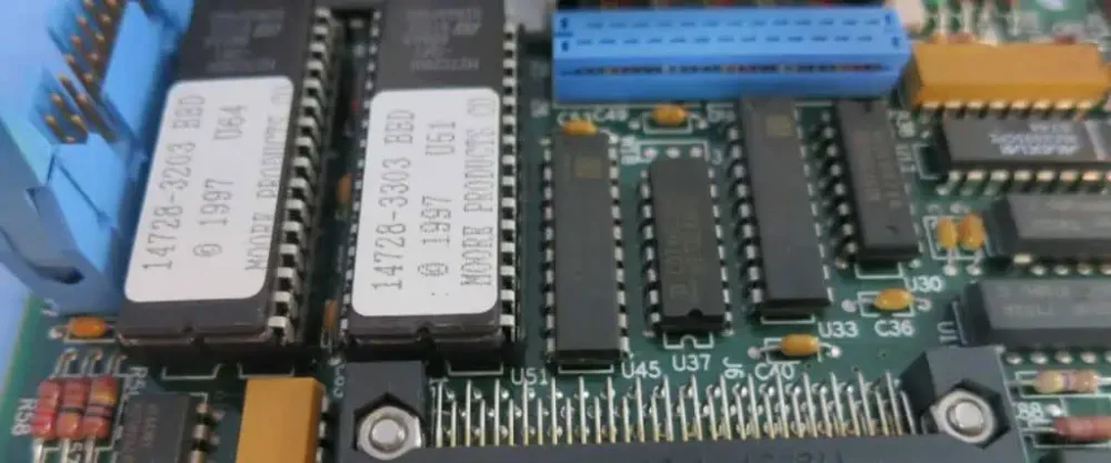
Freeze the configuration that the station must recognize
Identify the PCB revision, fitted BOM variant, processor or module revision, firmware image and channel assignment. Record how the operator or fixture distinguishes variants that look similar. A board can accept the correct firmware family while still carrying a different output stage or connector mapping.
Provide the manufacturing files and a release index. Include fitted/not-fitted instructions, approved alternatives and the identity format applied to each unit or lot as required. If customer-supplied devices arrive preprogrammed, define what verification remains necessary and how their identity joins the assembly record.
Use the industrial manufacturing release guide to resolve inconsistent files before quoting. A build should not depend on an operator interpreting an old photograph or a private email exception. Changes to the firmware, BOM or test limits must be traceable to the configuration they affect.
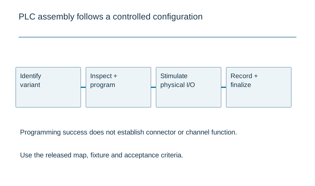
Programming and physical tests have different outcomes
| Operation | Useful observation | Do not infer |
|---|---|---|
| Image verification | Intended firmware/configuration identity | Every external channel works |
| Input stimulus | Response to the declared electrical input | All installation fault cases are covered |
| Loaded output check | Behavior under the test load | Complete machine response or protection |
| Finalization | Required label and shipping configuration | Unperformed product integration tests |
Separate programming from verification of physical I/O
Programming places the intended image on the device and may set configuration values. Verify the programmed identity through the supported method, but do not treat that operation as a test of the external channels. A valid image can run on a board with an open solder joint, incorrect input component or miswired connector.
Define a stimulus and expected response for each relevant channel type. Digital input tests should account for the specified electrical interface; analog tests need stated ranges and measurement conditions. Output tests require representative loads or an explained substitute. Communication checks must identify what is actually exercised beyond a connector being present.
The PLC hardware-mapping guide connects terminals, process-image behavior and application symbols. Manufacturing acceptance should use the released mapping and the agreed test application. The machine's full functional validation may require later integration and must not be inferred from a standalone board test.
| Review item | What to establish |
|---|---|
| Variant identity | PCB, BOM, firmware, channel map and a reliable means to distinguish builds. |
| Programming | Approved image, configuration values, identity check and final state. |
| Physical test | Defined stimulus, load, measurement boundary and response for each channel type. |
| Station capacity | Complete cycle duration, usable time and genuinely independent resources. |
| Delivered record | Required identities, test references, retest history and integration exclusions. |
Design a station sequence that preserves failures
A practical route can include identification, inspection, controlled power application, programming, electrical tests and final labeling. The actual order follows the design and test risk. Do not power an assembly merely because an earlier step is inconvenient; define the entry criteria and any controlled conditions needed for the station.
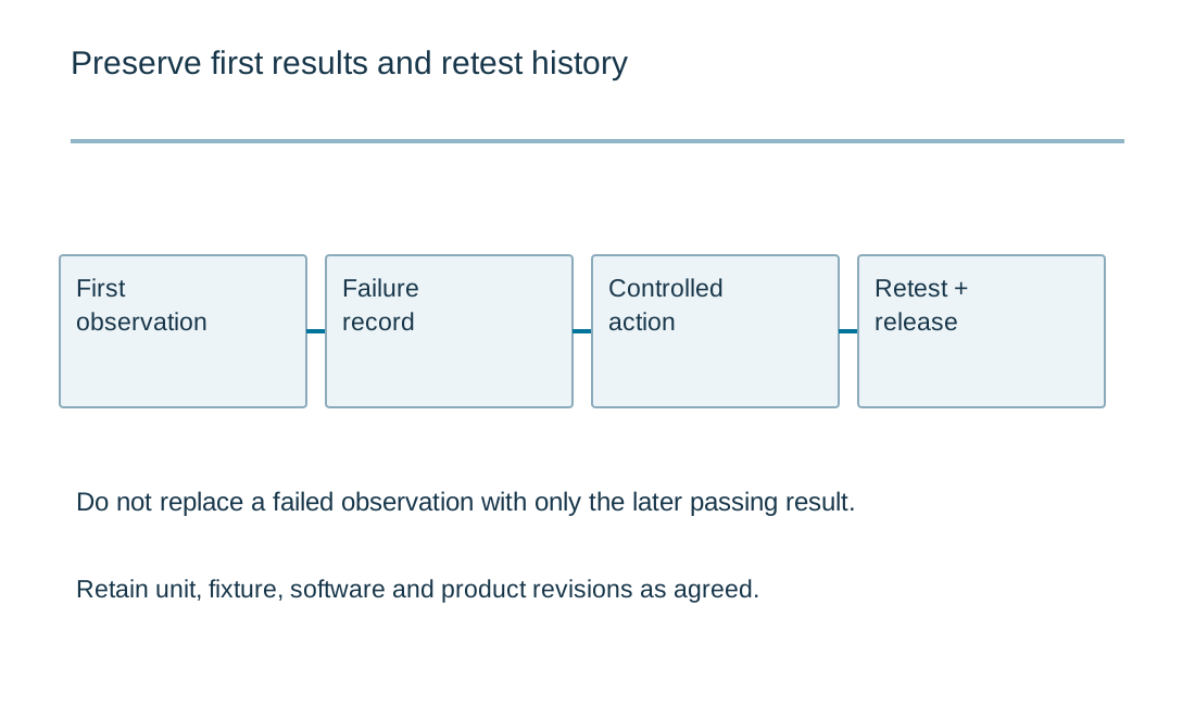
Record first results, diagnostic actions and retests according to the agreed process. Repeating a test until it passes can hide an intermittent problem. When the fixture or software changes, retain its revision so results can be interpreted later. Define how reference units or other appropriate checks establish that the station itself remains usable.
Plan handling after test: removal of temporary jumpers, connector protection, final switch position and any required cleanup state. A successful test followed by an incorrect final configuration produces the wrong delivered object. Make those closing operations visible in the work instruction rather than assuming they happen automatically.
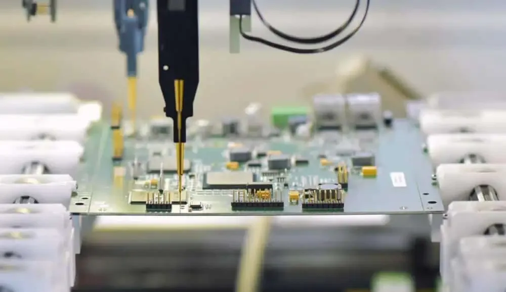
Production test station capacity
Production test station capacity
Use the current inputs and keep the assumptions
Load the example to see the units and record format, then clear it before entering your own revision. Example values are illustrative and do not select components or establish acceptance limits. Every field needs an intentional value; a blank number is not treated as zero. For CSV input, retain the header and put one item on each row. Quoted cells can contain commas, but duplicate headers and malformed rows are rejected.
Generate a result only after checking the measurement boundary, operating condition and units. Editing an input invalidates the old result and disables its download until you calculate again. An edited example stays labeled as an example. The report is created locally; it does not upload a design, send an enquiry or populate the Contact form. Attach it manually if it helps explain a requirement. You can contact RAYPCB without completing the tool.
| Input | What to establish before using it |
|---|---|
| Review reference | Use a nonconfidential revision label. |
| Station occupancy per unit · s | Include load, programming, measurements and unload when they occupy the station. |
| Independent parallel stations | Integer; stations must actually be able to operate concurrently. |
| Scheduled time · h | Length of the planning interval. |
| Usable scheduled fraction · % | Entered allowance for downtime; not an observed factory performance claim. |
| Units planned | Integer; first-pass cycles only. Retest and yield require separate evidence. |
Optional cost comparison from your own allowances
Use a quotation or a clearly labeled internal assumption for each input. Keep the quantity, construction and inspection scope the same when comparing alternatives. This uncalibrated planning model adds entered values; it contains no current market rates and does not issue a RAYPCB quotation. You can contact the team without completing it.
Assembly scope allowance comparison
Estimate complete cycles, not fractional finished units
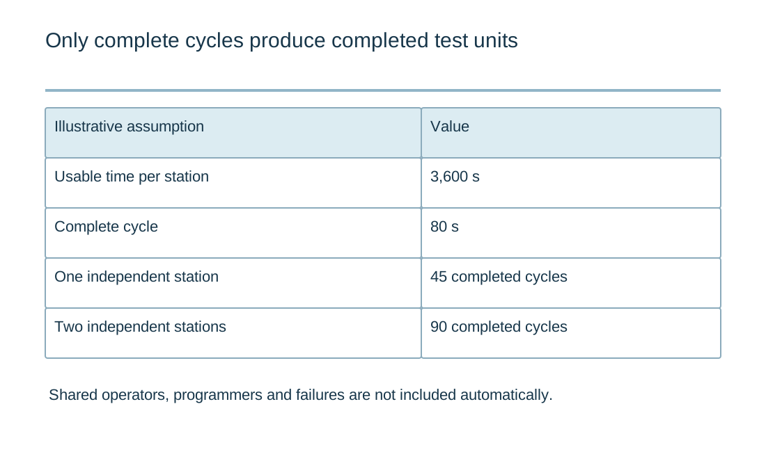
The local capacity tool uses your declared usable time, cycle duration and independent parallel stations. It counts only complete cycles within the available interval. If a station has 3,600 usable seconds and each complete cycle takes 80 seconds, it can complete 45 cycles under that simplified assumption. Two genuinely independent stations give 90 cycles.
The assumptions matter. Loading time, operator availability, shared programmers, server response, warmup, changeovers and failures can reduce usable capacity. Enter them in the time boundary or evaluate them separately without double-counting. Two sockets are not two independent stations if they wait on one shared resource.
For a requested quantity, the tool also indicates the number of complete cycles per station needed under its allocation model. This is planning arithmetic, not a promised delivery date. A pilot run with the actual fixture and configuration should establish the measured cycle and variability used in production planning.
Build a cost comparison around included operations
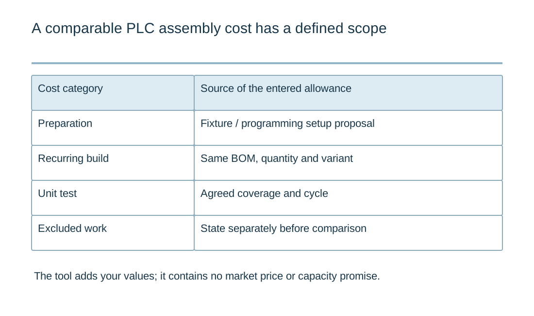
Separate one-time preparation, recurring assembly or unit allowance and the test allowance per unit. Keep currency and quantity consistent. The optional cost model contains no supplier price database: it adds entered values so two scenarios can be compared on a visible basis. Label internal assumptions and retain the source of actual quotations.
A lower assembly allowance is not necessarily a lower delivered cost if programming, fixture development, calibration or reporting is excluded. State who supplies parts, loads and test equipment, and how approved substitutions are handled. Identify packaging and delivery conditions separately if they are not included in the entered values.
Changes to test coverage can alter recurring time and one-time work. Compare like-for-like configurations before attributing a cost difference to a supplier. If essential requirements remain open, request a scoped engineering review rather than presenting the calculator total as an exact quotation.
Hand over a controller with an understandable record
Define the records delivered with the assemblies: identity, revision, programming reference and agreed test results. Decide which records are per unit and which belong to a lot or setup. The format should support the customer's acceptance and service needs without collecting unnecessary confidential information.
If the controller is delivered inside a replaceable subsystem, the electronic module assembly guide helps define the interface and remaining integration tests. Do not assume that a passing board automatically establishes the behavior of its power supply, harness and enclosure combination.
Send RAYPCB the release index, quantity, supplied-material scope and the required programming/test sequence. Highlight unresolved fixture or channel-test questions. The resulting enquiry can distinguish PCB assembly work from application programming and system validation, making both the technical review and quotation more useful.
Quote a repeatable test sequence
Describe what enters the station, what the station does and what a released unit must contain. Programming, calibration, electrical test and labeling consume different resources and produce different records. A cycle-time estimate is only meaningful when the station boundary is explicit and the required equipment can operate as assumed.
Use one controlled revision for the board, BOM, fixture software, firmware image and acceptance criteria. Define how failures are contained and how retests remain visible rather than replacing the first result. Identify any customer-supplied credentials or fixtures through a controlled process; do not place secrets in a public worksheet. A quotation can then distinguish setup work, recurring assembly and the agreed evidence package. Neither a downloaded checklist nor a successful firmware load proves every external channel works.
Standards, source context and limits
Use the exact device, system and material documents relevant to the released design. A public reference design demonstrates a particular implementation under its stated conditions; changing its parts, layout, enclosure or firmware creates a different verification task. Standards summaries here identify the type of evidence to request, not every clause of a licensed standard. Component qualification, board workmanship, product validation and regulatory acceptance are separate decisions.
For fabrication scope and the agreed construction requirements, see PCB manufacturing.

