Streamlining Circuit Design with Online Circuit Diagram Makers

Online Circuit Diagram Maker

With the continuously advancing technology, trial-and-error methods need to be updated. We are now making work more accessible by generating sample models to ensure its functioning before making the ultimate tangible structure. Online circuit diagram makers are a great way to quickly and easily create professional-looking circuit diagrams. These tools can help you take your circuit diagram to the next level, from simple designs to more complex projects. Whether you are a beginner or an experienced circuit designer, these online circuit diagram makers can help you easily create your diagrams. This article will discuss the online circuit diagram maker, its benefits, and how to achieve the best possible diagram. Finally, we will examine the top three most famous online circuit diagram-making software.

What is an Online Circuit Diagram Maker?

An online circuit diagram maker is software that enables users to generate and edit schematic diagrams, commonly known as circuit diagrams, using a web browser. Typically, this software includes a library of pre-made components and symbols that may rapidly and easily generate a circuit diagram.

Benefits of an online circuit diagram maker

Online Circuit Diagram

Utilizing the online circuit diagram maker accrues the user the following benefits:

1. Time savings:

Using online circuit diagram generators, creating complex electrical diagrams is easy and quick. Users can reduce the time it takes to make a circuit diagram from scratch by using an online circuit diagram maker. This is extremely helpful for engineers and technicians who must work precisely and rapidly to generate diagrams.

2. Cost-effectiveness:

It can be expensive and time-consuming to create a circuit diagram. However, users can save money using an online circuit diagram builder instead of buying expensive software and gear. This cost-effectiveness makes it a desirable option for engineers and technicians who need to create complex diagrams quickly.

3. Flexibility:

Online circuit diagram generators allow customers to modify their diagrams to suit their requirements. Users can alter the design as they see fit owing to this flexibility. Additionally, users can change the size and shape of the diagram as well as add or remove components and wires, for instance. This feature enables users to design diagrams that are specific to their requirements.

4. Accuracy:

Users can use an online circuit diagram maker to ensure their diagrams are correct and current. This is particularly crucial for engineers and technicians who need to present their diagrams professionally. Users can create accurate and current circuit diagrams with an online tool, which is essential for any project’s success.

5. User Friendly:

Online circuit diagram generators are simple to use and user-friendly. As a result, novice users can easily create intricate diagrams without prior experience. Notably, any user can quickly construct diagrams without any technical knowledge due to this user-friendliness.

6. Flexibility:

Users can generate circuit diagrams for a range of purposes using online circuit diagram makers, which are flexible. As a result, they may quickly draw diagrams for a wide range of systems and applications. Engineers and professionals that need to draw diagrams for various objectives will find it a desirable alternative due to its adaptability.

7. Teamwork:

Online circuit diagram generators let users work together on their diagrams. People can contribute to the design with this feature by sharing their diagrams with other users. The accuracy and currentness of the finished product can be easy to achieve with this partnership. Additionally, it enables users to swiftly make adjustments and guarantees that everyone uses the same schematic version.

How to Make an Excellent Circuit Diagram Using the Online Circuit Diagram Maker

FULL PCB MANUFACTURING Quote

The quality of your circuit diagram will depend on how well you carry out the designing process on the circuit diagram maker. The following are some simple iterations that will get you to a superb circuit diagram:

1. Establish the purpose and target market for your circuit diagram.

A circuit diagram’s purpose is to show how an electrical circuit works and the various parts that go into it, including power sources, switches, resistors, transistors, and more. The diagram should be simple to read and contain all the details needed to construct and maintain the circuit. A circuit diagram’s target audience can range from seasoned electrical engineers to amateurs or students. To make a simple diagram to read and comprehend, please ensure you have customized it for the audience.

2. Drag & drop components into the Shape Library after choosing.

The first step when utilizing an online circuit diagram builder is to choose the shape library. The circuit diagram will consist of the shapes and symbols in this collection. Many shapes and symbols, including power sources, switches, resistors, transistors, and others, are available from most online circuit diagram designers. After choosing the shape library, please drag and drop the parts into the diagram. To do this, remove the component into the diagram with the mouse after moving it over it. This is a simple and quick technique to include elements in the diagram.

3. Draw the intended connections.

Now draw the connections and format them after adding the components to the circuit diagram. This step entails drawing lines to link the components together and styling the lines to indicate the nature of the connections. For example, a solid line may denote a power connection, whereas a dotted line may denote a ground connection. This phase is crucial to ensure the accuracy and clarity of the circuit diagram.

4. Drop and Name Power Sources

Next is dropping and designating power sources. This process entails naming the power sources after adding them to the circuit diagram, such as batteries or power supplies. This phase is crucial to ensure the accuracy and clarity of the circuit diagram. To make the circuit diagram easy to understand, it is also essential to ensure that you have appropriately identified the power sources.

5. Examine and Share

Reviewing and disseminating the circuit diagram is the last stage. This step entails checking the circuit diagram for accuracy and clarity before distributing it to the intended audience. Before sharing the circuit diagram, please make any necessary modifications or corrections. Once you have examined and discussed it, your circuit diagram is ready for use.

Top Three Best Online Circuit Diagram Makers

8 Ways to Restore PCB Schematic Diagram According to PCB Board

The following are the top three most famous online circuit diagram making softwares:

EdrawMax

Edraw Max, an online circuit diagram maker, helps simplify the process of designing circuit diagrams quickly and simply. With this robust yet user-friendly application, you may quickly and easily generate circuit diagrams with a professional appearance. In addition, the software includes a wide range of features that make it the perfect choice for inexperienced and seasoned circuit designers.

Features

With its many capabilities, Edraw Max is the best option for drawing circuit diagrams. Your diagrams can be easy to create using the program’s drag-and-drop interface. It also provides a vast selection of symbols and templates that you may use to make your diagrams. Additionally, various tools for connecting objects, adding elements, and adding labels are available in the software. Additionally, it features a library of electrical parts and symbols that you may utilize to add extra detail to your diagrams.

Pros

Edraw Max is a user-friendly UI. Even novices can quickly and easily create circuit diagrams that look professional owing to the program’s simple usage and comprehension. Furthermore, it has various features that make it perfect for seasoned circuit designers. For example, you can use the program’s library of electrical parts and symbols to add more detail to your diagrams.

Cons

Edraw Max only has an English version. This feature might make it difficult for users who need to speak English better. Furthermore, the program does not have a free trial version, so you must buy a license before using it.

Lucidchart

Lucidchart is an online tool that makes creating circuit diagrams quick and straightforward. With this robust and user-friendly platform, you may quickly generate great circuit diagrams with an excellent appearance. In addition, the software has many features that make it the perfect choice for novice and experienced circuit designers.

Features

Lucidchart offers many features to help you create and customize your circuit diagrams. These features include an extensive library of symbols and components and a powerful drawing interface that makes it easy to create and customize your diagrams. You can also use it to share your diagrams with others, as it supports multiple file formats and cloud storage options.

Pros

Lucidchart’s user-friendly, and anyone can easily use it. Furthermore, it has a comprehensive library of symbols and components. It also supports multiple file formats and cloud storage options. English, Spanish, French, and German are just a few of the languages that Lucidchart offers.

Cons

Lucidchart is not free software. Although there is a free version of the program, it has few features and can only be helpful for personal projects. Additionally, the program needs a library of electrical symbols and parts, which can be problematic for skilled circuit designers.
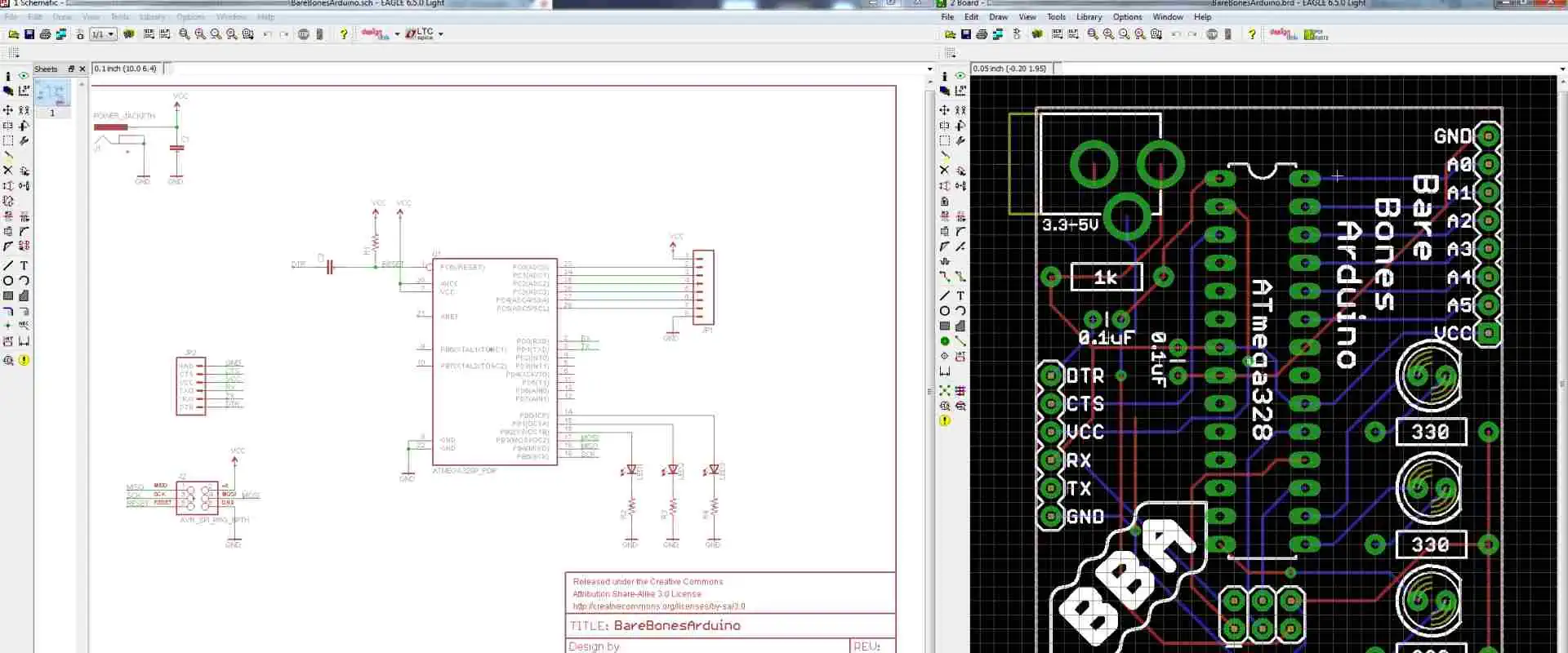
Autodesk Eagle

autodesk-pcb

Autodesk Eagle is a powerful online circuit design software that can help create professional-looking circuit diagrams. It has many features and tools that make it easy to create and customize your diagrams. It also supports multiple file formats and cloud storage options, making it easy to share your diagrams with others.

Features

The numerous capabilities of Autodesk Eagle make the process of creating circuit diagrams simpler. The software offers a schematic editor, a PCB layout editor, and a library of parts and components to assist users in the design process. It also features collaboration capabilities for working with distant teams and tools for automated routing, design rule checking, and 3D visualization. Eagle by Autodesk is accessible on both Windows and Mac.

Pros

Autodesk Eagle is a powerful and user-friendly PCB design software that can be used by hobbyists and professionals alike. It is relatively easy to learn and master and allows users to quickly and easily create complex PCB layouts. Autodesk Eagle is also available in various languages, including English, Spanish, French, and German.

Cons

Autodesk Eagle’s inability to be downloaded for free is one of its main drawbacks. Although Autodesk Eagle provides a free edition, its functions, and features are subject to severe constraints. Notably, Autodesk Eagle’s complete edition requires a yearly subscription fee, which may be too expensive for specific users. Additionally, a learning curve is associated with using Autodesk Eagle’s user interface before you can maximize it. Finally, Autodesk Eagle is incompatible with Mac OS.

Conclusion

Creating a circuit diagram is essential in understanding and building electrical circuits. However, creating circuit diagrams can be daunting, but with the right tools, it can be much easier. From the above details, using an online circuit diagram maker, it is easy to create an accurate and easy-to-understand circuit diagram.

Raspberry Pi Zero, The Tiny Pi that is Changing the Electronics Industry

Raspberry Pi Zero Board

There is a reason why suppliers often tend to limit the amount of raspberry pi Zero gadgets that a single person can buy. Even in this price-plummeting era of electronics that are mass-produced, there is literally no electronic product that you can purchase for 10 USD that offers as much as the raspberry pi zero. Moreover, demand for the raspberry zero can quite easily outweigh production leading to unsatisfied customers. But what makes this device popular? Which features does the raspberry pi zero have? Is the raspberry pi zero as or more efficient than other raspberry pi versions? And should you consider purchasing a raspberry pi zero?

Raspberry Pi in a Nutshell

Raspberry pi PCBs (printed circuit boards) are unique circuit boards. Moreover, raspberry pi devices come in many different variations, which include the popular raspberry pi zero.

Typically, raspberry pi PCBs are a series of comps designed by the raspberry pi company. Moreover, these devices utilize a special type of circuit board known as a raspberry pi printed circuit board.

The Connections between Raspberry Pi and Printed Circuit Boards

Printed circuit boards are sheets of insulating components, for example, fiberglass, which has metallic tracks or circuits etched or printed onto them for efficient electrical conductivity. Moreover, printed circuit boards are found in most electronic products such as satellites, airplanes, military weapons, mouse, keyboards, laptops, computers, TV, Tablets, mobile phones, et cetera.

On the other hand, raspberry pi circuit boards are circuit boards that have a combo of castellated holes and through holes with pitch pin headers. Typically, Raspberry pi circuit boards are computer circuit board that features credit card sizes. Therefore, their size is ideal in terms of carrying out various tasks. Moreover, though compact, raspberry pi devices can carry out complex tasks such as:

  • Executing games
  • Word processing
  • Generating spreadsheets

Raspberry pi devices are generated by the raspberry pi company. Moreover, this tech has been around since 2012.

Raspberry pi gadgets were developed to help improve the following:

  • Learning
  • Innovation
  • Experimentation

Moreover, raspberry pi circuit boards are portable PCBs available on all raspberry computers. Most raspberry pi circuit boards available in the market today are installed in mobile phones.

As per classifications, raspberry Pi circuit boards can be classified into two categories according to the model type. These raspberry models are model A and model B:

Model A

Model A Pi circuit boards utilize less power during operation. Moreover, these raspberry pi PCBs donโ€™t feature Ethernet ports.

Model B

Model B pi circuit board, on the other hand, consumes more power during operations. Moreover, they also have Ethernet ports for wired WiFi connections and LAN connections.

Lastly, raspberry pi devices are open source. Therefore you can customize them to meet your desired needs.

The Raspberry Pi Zero

FULL PCB MANUFACTURING Quote

Even though the raspberry pi zero is efficient, the first thing that will strike you by surprise is how much it costs. Before you even move on to the specs of the pi zero, how to set it up, and the many different ways that you can utilize these devices, you will have to first thank the manufacturers of the raspberry pi zero for generating a 5 USD 32-bit desktop computer that can support a Linux operating system.

Of course, by trying to cut costs, the company might have compromised a bit on performance, where for example, you will find that these pi devices take longer to boot. However, when you purchase the raspberry pi zero circuit board, the part you get will only cost you 5 USD. To make it run efficiently, however, you will have to add other components to the board. However, the additional commodities are simple parts you might already have at home.

The Size of the Raspberry Pi Zero

After the price, the next thing that will surprise you is the size of the raspberry pi zero. On average, the raspberry pi zero measures 6.5 cm x 3cm. Moreover, this device is only 0.5cm thick, and its thickness mostly comes due to the various connectors embedded into the circuit board, such as the mini HDMI connectors.

The original model of the raspberry pi series is heavily utilized in many different applications. However, these raspberry pi circuit boards were relatively larger and mostly looked unwieldy or clunky when integrated into a robot or other intelligent projects. On the other hand, the popular raspberry pi zero is elegant and slim, and due to its small size, it can be utilized in many projects.

Specifications of the Raspberry Pi Zero

Raspberry Pi 3B
Raspberry Pi 3B

The raspberry pi is a power device that bears the following specifications:

CPU and GPU

The raspberry pi zero runs on a one gigahertz ARM 11 Broadcom central processing unit. Moreover, like most raspberry pi devices, this pi circuit board runs on a Videocore IV graphical user interface.

Memory and Storage

As per storage, the raspberry pi zero has a slot for microSD that you can utilize to host your operating system. Moreover, the device also comes with 512 MBs worth of memory to get you running.

Connectivity

When it comes to connectivity, the raspberry pi zero has the features:

Operating System and Connectors

The raspberry pi zero runs on a Linux operating system. Moreover, this pi circuit board comes bearing the following connectors:

  • 12C
  • SPI
  • Unpopulated 40-pin GP-Input/Output header

Price

Even though the raspberry pi circuit board is efficient and comes bearing multiple features that make it stand out, it also features an astonishingly low retail price of around 5 to 4 USD.

Design

Raspberry Pi 4
Raspberry Pi 4

When it comes to the design of the raspberry pi zero, there is no sugarcoating this. You get a printed circuit board design, nothing else. But for 5 USD, you can’t really complain about not getting any type of casing that most consumer-level electronic products come bearing. But this is beside the point; that’s because the raspberry pi zero is meant to be extremely cheap, raw, versatile, and cheerful so that professionals and hobbyists alike can explore the limits of this gadget.

However, for the raspberry pi company to achieve the target price and size, they had to cut off some features on pi zero, which are present on pi 1 and 2.

At first glance, the first thing that you will most probably note is that the SoC is near the center of the circuit board. Moreover, the board’s ports are at the bottom part of the circuit board.

The raspberry pi zero circuit board also has a single mini HDMI port which you can utilize to connect the board to a display. Moreover, the board also comes bearing two micro-USB ports which function as follows:

  • One is for power
  • The other is for data, or simply useful for normal micro-USB functions.

A close look at the micro-USB ports

To utilize these micro-USB ports to integrate various peripherals, for example, a mouse or a keyboard, into the circuit board, you will require a USB A female to micro-USB B male adapter.

However, another thing you will note about the design is that it misses Ethernet ports. Therefore, the lack of Ethernet ports means you cannot connect this pi circuit board to the internet or a network without adding USB Ethernet ports or WiFi USB dongles.

On the left side of the circuit board, you will note that the raspberry pi zero contains a microSD slot. However, these pi device lacks built-in flash memory like the pi two and pi 1; therefore, after purchasing the pi zero, you will have to buy a microSD card that will host the board’s operating system and store data.

Hardware

After purchasing the raspberry pi zero, you get multiple hardware components functioning in unison to make the pi zero efficient. One of the main hardware components you will get will be a fully functional 32-bit Comp that runs on a one gigahertz ARMv6 microprocessor (single core. Moreover, you also get a working videoCore four GPU plus 512 megabytes of memory.

The boardโ€™s GPU has the ability to drive a full High Definition (HD) display at around 60 fps. Moreover, on top of getting RAM and SoC, the pi zero also comes bearing 40 GPIO ports that you can utilize to execute various connections. These 40 GPIO ports are the forty-plated holes that you will find on the top side of the board. However, you should note that the ports are unpopulated, meaning they do not have pins. Moreover, these headers are compatible with raspberry pi two and pi one versions. However, since they do not have pins, to utilize this header, you will have to solder the cables to the holes.

Due to their size and energy efficiency, the raspberry pi zero circuit boards can run on an external battery, making them efficient in portability. Moreover, their portability and size make them the perfect raspberry pi boards to use on robotic projects. Furthermore, they are also great portable computers because you will only need to carry the board, a batter, and a WiFi dongle, and that is it. You have a working Linux PC.

Conclusion

When it comes to making raspberry pi circuit boards cheaper, smaller, and faster, we give credit to the raspberry company for doing a great job. However, in terms of eliminating faults that make the raspberry pi less efficient in terms of performance, you will note that the company hasn’t done an excellent job. That is because, even though pi zero is efficient, it still carries forward the weaknesses of the original raspberry pi. However, despite these downsides, the raspberry pi is still pretty efficient and fast. Therefore, if you are looking to purchase one, we recommend you go for it.

Reasons why you should consider RFI Coating

RFI Coating

Technology has become a significant part of our day-to-day lives. We have tech gadgets that help us perform simple tasks, such as ordering our groceries, to complex ones that help surgeons perform surgeries remotely. However, for these gadgets to function optimally, all their components must be working correctly. If anything alters the functionality of the components in a device, it could cause a lot of havoc in certain situations, such as the remote surgery situation.

Electronics manufacturers are now taking EMI and RFI shielding seriously. That is because RFI or radio frequency interference has the ability to make various gadgets function abnormally or even fail. However, to solve this issue, manufacturers have developed different RFI shielding methods which involve RFI Coating. But what exactly is RFI coating? Why is Radio frequency interference coating crucial to electronic gadgets? And why should you go for this type of RFI shielding?

RFI in a Nutshell

Radiofrequency interference or RFI is simply the radiation or conduction of RF energy that causes electrical devices or electronics to generate noises which ultimately causes interference to gadgets nearby. Moreover, RFI also describes how radio astronomy disrupts the normal operations of satellites by causing interference.

RFI can disturb and ultimately disrupt how electrical devices and electronics operate, so it is vital to deal with it before it causes your gadgets to fail.

How Does RFI Occur

RFI is usually emitted by electronic gadgets such as:

–          Computing devices

–          Game consoles

–          Laptops

–          Personal computers

–          Electronic printers

–          Medical instrumentations

–          Industrial controls

–          Switching power relays etc.

Moreover, these electronic devices emit RFI in one of these two methods:

–          The first method involves the gadget itself emitting RFI into the surrounding areas

–ย ย ย ย ย ย ย ย ย  The second method involves the RFI being released into AC power lines via power cords of various electronic components or electronic devices.

On the other hand, as per satellite communication, RFI can occur in two methods, intentionally or naturally. First, various types of space weather, for example, solar storms, have the ability to cause natural RFI. Man-made Interference, on the other hand, falls under intentional RFI, which means that these RFIs do not occur naturally.

Proper RFI shielding on electronic devices helps in terms of controlling radiated RFI. Moreover, power line filters can easily control conducted RFI to acceptable or satisfactory levels. As per satellite communication, the utilization of impeccable end filtering and directional antennas can help you curb narrowband RFI. However, in the case of broadband RFI interference, you will have to modify the source to tune down the RFI interference.

The Difference between Radio Frequency Interference and Electromagnetic Interference

FULL PCB MANUFACTURING Quote

EMI (electromagnetic interference) and RFI (radio frequency interference) are generated by and negatively affect electronic gadgets. In most cases, people utilize these two names interchangeably because radio waves tend to be part of the vast electromagnetic spectrum. However, it is crucial to note that even though RFI and EMI and pretty similar, they aren’t the same.

Electromagnetic interference generally refers to short-range interference that comes from the emissions of high frequencies from the electrical gadgets themselves causing electrical noise. On the other hand, RFI has longer wavelength interferences and occurs from external sources. Moreover, EMI and RFI both negatively impact electrical gadgets in different manners.

Conductive coatings are usually utilized to effectively attenuate and even reduce EM and RF waves. Moreover, both RFI and EMI shielding coatings contain layers of conductive elements that helps shield the device from RFI generated by internal component and external devices. Additionally, to offer stronger solutions, manufacturers also utilize conductive paints.

Modern enclosures utilized on electrical gadgets are often made using plastic. However, plastic does not offer intrinsic protection against RFI and EMI. However, to get around this issue, the manufacturer utilizes conductive paint on the plastic enclosures to make the sensitive electronic devices more RFI and EMI-proof. Moreover, board components are usually shielded using metal caps.

RFI Conductive Coating

PCB Assembly conformal coating

RFI coatings are typically protective lacquers that have conductive components. Moreover, to generate these coatings, manufacturers utilize various highly conductive metal components, which include:

–          Copper

–          Aluminum

–          Zinc

These coatings are utilized on various non-conducting composite casing components, which helps shield the electrical circuit of sensitive devices from RFI.

Moreover, manufacturers also utilize nickel, graphite, and carbon coating to generate RFI coatings used in various applications, which include:

–          Utilizations in cellphones

–          PDAs

–          Aerospace gadgets

–          Military electronic equipment

–          Medical devices heavily utilized in the medical industries

–          Industrial equipment

–          Telecommunication gadgets

–          Consumer electronics

Moreover, these types of RFI coatings can also be used on drywalls, which comes in handy when trying to shield an entire room from RFI.

Additionally, other materials, such as silver, can also be utilized to generate RFI coatings that function impeccably, even in harsh conditions. Moreover, silver coatings can also act as conductive bases for various applications that require the surface to have high conductivity.

Silver is also non-magnetic, which means that it offers impeccable levels of permeability, which are great for the production of RFI coatings.

Benefits of Utilizing Radio frequency interference Coatings

pcb coating spray
pcb coating spray

The main advantage of obtaining RFI/EMI coatings is that it helps shield your device from RF waves which can cause your device to malfunction. However, this isn’t the only advantage that comes with RFI coating. That is because by installing an Radio frequency interference coating, you get to enjoy impeccable point-to-point resistance and practical attenuation that helps contribute to superior performance in terms of your gadget’s protection while at the same time leaving it anti-static. Moreover, your device also benefits from a uniform thickness that gives it a unique finish.

Therefore, by putting a radio frequency interference coating on your electrical gadget, you do not just make it more EMI and RFI-proof. You also improve its reliability and efficiency. Hence you should really consider RFI coatings as an option for RFI shielding.

Common Items that require Radio Frequency Interference Coating

Radio frequency interference coating come in handy for most electrical gadgets that are usually at risk of RFI. Here are the most commons electrical gadgets that require Emi RFI shielding coatings:

–          Process control components

–          Mobile phones

–          Computers

–          Radios

–          Medical devices, for example, X-ray gadgets

–          Marine electronic gadgets

Conclusion

Radiofrequency and electromagnetic interference are huge issues for electrical and electronic device manufacturers. That is because these two can cause electrical and electronic gadgets to malfunction or even fail to function entirely. Moreover, RFI and EMI are hard to avoid, so the only things that manufacturers can work with are RFI and EMI coatings and shields. Therefore we hope that this article has provided you with all the answers that you were looking for regarding RFI coatings.

The Best 15 Soldering Iron Kits, Which One Do I Need?

soldering kit

Soldering kits are essential for anyone looking to take up soldering as a hobby or a profession. There are a variety of kits on the market, each offering different accessories and features. Depending on your needs, you can choose a range of soldering kits with adjustable wattage, ergonomic design, lead-free solder, temperature range, and various tips for different soldering techniques. With the suitable kit, you can be sure that your soldering projects will be done with precision and accuracy.

Soldering kit 

A soldering kit is a collection of tools used for soldering, which is the process of joining two or more metal components together by melting a metal alloy and applying it to the joint. A soldering iron, solder, flux, wire cutters, and other tools are usually part of the package. In addition, the kit may include safety equipment such as safety glasses, gloves, and a soldering mat.

1. The Anbes Soldering Iron Kit

soldering kits

The Anbes Soldering Iron Kit is perfect for those looking to do light soldering work at home. This package includes a soldering iron, a soldering iron stand, and safety equipment like a desoldering pump and tweezers. It also has all the materials needed to get started. A ceramic heating element in the soldering iron heats up quickly and maintains a steady temperature. You may set the precise temperature required for the task with the user-friendly adjustable temperature control. The supplied stand keeps the soldering iron safe while in use and is sturdy and secure. Engineers can easily remove any extra solder on the workpiece with the help of the desoldering pump and tweezers.

2. Weller WLC100 Soldering Station Iron Kit

The Weller WLC100 Soldering Station Iron Kit is a full-featured soldering station suitable for any level of the soldering technician. This kit includes a soldering iron, a soldering stand, and various tips and accessories to help you complete the job right. You may fine-tune your soldering temperatures by using the soldering iron’s adjustable temperature range of up to 900ยฐF. The soldering stand’s design prevents hand fatigue and allows you to adjust the angle of the soldering iron easily. The tips range in size and shape from fine-point to chisel-tip, letting you choose the best one for the job. This soldering kit includes a desoldering pump, wick, solder, and other station equipment. Additionally, the WLC100 Soldering Station Iron Kit is an excellent tool for any soldering as it will help you achieve professional results every time due to its adjustable temperature range, ergonomic design, and choice of tips.

3. Tabiger Soldering Iron Kit

Tabiger Soldering Iron Kit is a comprehensive and versatile soldering kit that offers various features for hobbyists and professionals. It is suitable for soldering applications such as circuit board repair, jewelry making, and more. The kit comes with a soldering iron, solder wire, desoldering pump, a soldering iron stand, tweezers, a soldering aid, and other accessories.

The soldering iron is strong, making it suitable for amateurs and professionals. It is temperature adjustable up to 400ยฐC and includes a heat-resistant rubber grip for comfort. In addition, the integrated desoldering pump helps remove excess solder from circuit boards and other components quickly and easily.

The soldering aid is a multipurpose tool that holds small components in place when soldering, making the job considerably more manageable. While soldering, the tweezers help grip and move tiny components. The stand is also necessary for keeping the iron safe when not in use and also serves as a handy tool holder.

4. Hakko FX888D-23BY Soldering Iron kit

FULL PCB MANUFACTURING Quote

The Hakko FX888D-23BY is a soldering iron kit that consists of the FX-888D soldering station, a T18-D16 soldering tip, a PH-50 stand, and a cleaning sponge. The temperature range of the FX-888D soldering station is 120ยฐC to 480ยฐC (248ยฐF to 896ยฐF). This soldering station has a digital display and an adjustable temperature control, making it simple to set and maintain a precise temperature. The T18-D16 soldering tip consists of high-quality stainless steel and creates a unique and dependable connection. The PH-50 support has three prongs that securely hold the soldering iron and tip. Finally, the accompanying high-density foam cleaning sponge cleans the soldering tip after usage.

5. Vastar Soldering Iron Kit

Experienced and novice solderers will find Vastar’s Soldering Iron Kit an excellent choice. This beginner kit includes various other parts and a soldering iron. The iron’s handle is simple to use and ergonomically designed. Temperature control with adjustability and an LED indication also allows precise temperature control. Also included in this set are a stand, a soldering tool, a solder wire, extra tips, and a cleaning sponge.

Additionally, it provides five unique tips for a range of soldering activities. Safety was another consideration in the design of the Vastar Soldering Iron Kit. It incorporates an on/off switch and an insulated, heat-resistant handle to avoid unintentional burns. Additionally, it includes a safety lock to keep the iron from turning on while being transported or stored. The stand holds the iron upright for increased convenience, with the accompanying tips made of high-quality materials to ensure adequate heat transfer.

6. Weller WSB25WB Soldering Iron Kit

The Weller WSB25WB Soldering Iron Kit is an excellent choice for a reliable and effective soldering tool. This kit includes the soldering iron, stand, cleaning sponge, and a tip cleaning needle, offering a complete set of tools for all soldering projects. The iron is a lightweight 25-watt iron with a comfortable ergonomic handle and a convenient on/off switch. The iron has a temperature range of 350ยฐF to 850ยฐF, allowing it to be compatible with various soldering tips. The included stand safely stores the iron and helps keep the surrounding workspace clean and tidy.

The cleaning sponge helps to remove excess flux, while the tip cleaning needle helps to keep the tip in good working order. The Weller WSB25WB is an excellent choice for any soldering project, from small electronics to larger projects. With reliable performance and an affordable price, this soldering iron kit is the perfect choice for a quality soldering tool.

7. X-Tronic Model Soldering Iron Kit

The x-Tronic Model soldering iron kit is ideal for inexperienced and seasoned hobbyists. The set includes a desoldering pump, a soldering iron stand with a cleaning sponge, soldering wire, five extra soldering tips, and a soldering iron with adjustable temperature. The soldering iron’s ergonomic shape makes it comfortable, and the adjustable temperature control enables perfect soldering. Transporting the kit to any workspace is simple, thanks to the package’s handy carrying case.

8. HANDSKIT Soldering Iron Kit

electronic assembly soldering

The HANDSKIT Soldering Iron Kit is a great option for individuals looking for simple and dependable soldering iron for their DIY projects and repairs. HANDSKIT Soldering Iron Kit comprises an anti-static stand, a soldering iron holder, a soldering iron sponge, a set of tweezers, a soldering iron stand, a heat shrinks tube, a soldering iron, and five soldering tips. The soldering iron’s temperature control dial enables precise heat adjustments up to 450 degrees Celsius. The soldering tips included in the kit come in three different shapes: chisel, flat, and sharp, enabling use with various heat settings and soldering techniques.

The anti-static stand helps to ensure that the soldering iron is always in a safe and secure position. The holder and sponge ensure the iron is kept clean and free of debris and flux. The tweezers and stand included in the kit help to make sure that all the components and wires are held securely while soldering. The heat shrink tube included in the kit is perfect for protecting electrical connections and features from smoke, heat, and moisture.

9. Hakko FX601-02 Soldering Iron Kit

The Hakko FX601-02 Soldering Iron Kit is a necessary tool for any professional or hobbyist in the field of electronics. The Hakko FX601-02 Soldering Iron Kit has everything you need to begin soldering. A soldering iron, soldering tips, a cleaning sponge, a stand, and an iron holder are all included. You may easily adjust the heat to the ideal level for your project with the soldering iron’s temperature range of 200ยฐC to 480ยฐC.

High-quality materials used in the soldering tips that come with the kit ensure a precise and tidy solder bond. The cleaning sponge aids in preserving the cleanliness and performance of your soldering iron. The soldering iron holder keeps your iron safe from accidental drops or falls. With the Hakko FX601-02 Soldering Iron Kit, you can be sure that your soldering projects will be done with precision and accuracy. This kit is an excellent choice for anyone looking to get started in electronics or as a great addition to any professional’s toolbox.

10. Plusivo Soldering Iron Kit

The Plusivo Soldering Iron Kit is an excellent choice for anyone looking to take their soldering skills to the next level. The soldering iron is adjustable from 5 to 120 watts and features an ergonomic design for comfortable use. The stand helps keep the iron off the work surface, preventing accidental burns and damage to the work area. Additionally, the coil of solder is made from a lead-free alloy, making it safe for use on various materials. The flux helps to ensure a good bond between the solder and the materials. Furthermore, the sponge and tweezers make cleaning up after soldering easy and efficient. With its adjustable wattage, the ergonomic design included accessories, and lead-free solder, the Plusivo Soldering Iron Kit is an excellent choice for any soldering project.

11. Aoyue 469 Soldering Station

The Aoyue 469 Soldering Station is a digital soldering station with a temperature range of 200โ€“480ยฐC. It has a 160W ceramic heating element and quick heating times, a soldering iron stand with a cleaning sponge, a soldering iron holder, and a soldering iron tip cleaner. Additionally, the station is designed for use with various soldering tips, and it can help in multiple soldering applications such as circuit board repair and small electronics assembly. The station also offers a range of safety features, such as an automatic shut-off and overheat protection.

12. UY CHAN Pocket-Size Soldering Iron Kit

Soldering Circuit Boards

The UY CHAN Pocket-Size Soldering Iron Kit is an excellent tool for any hobbyist or professional needing a reliable soldering iron. The kits comprise an adjustable heat gun, tweezers, solder, desoldering wick, tin wire stripper, soldering iron, and carrying pouch. It is also light and portable, making it an excellent choice for on-the-go projects.

Engineers can power the soldering iron with a 18650-lithium battery and a temperature range of 200โ€“480 degrees Celsius. In addition, the kit has a temperature for maintaining consistency. Engineers can remove the excess solder tweezers and desoldering wick. Furthermore, you can adjust the tin wire stripper to fit various wire sizes. In addition, the adjustable heat gun is ideal for larger projects, such as soldering circuit boards or heating more significant components.

13. Aoyue 9378 Soldering Station

The Aoyue 9378 Soldering Station is a versatile soldering station ideal for both experienced hobbyists and professionals. It includes a soldering iron station with temperature control, an adjustable stand, and a LED digital display. The unit also has a fume extractor and smoke absorber, making it ideal for soldering in confined spaces or laboratories. Additionally, the station incorporates a quick-change nozzle system, which allows users to replace their soldering tip fast and to match their demands.

The Aoyue 9378 Station is lightweight and portable, making it excellent for usage in several settings. The Aoyue 9378 Soldering Station is engineered for precision and accuracy. It has a temperature range of 150 to 480 degrees Celsius, allowing users to solder more precisely. The station also has an auto sleep option, which helps conserve energy when not in use. The adjustable stand of the station allows customers to change the soldering tip height to their demands, assuring precision and accuracy during soldering.

14. Weller WE1010NA Soldering Kit

The kit includes a WE1010NA soldering station, a WES51 soldering iron, a WEP70 iron holder, a WCC100 Tip Cleaner, and five additional soldering tips. Additionally, the WE1010NA soldering station has a digital LCD that shows temperature and tip numbers. Moreover, it has a built-in sleep mode that shuts off the unit after a period of inactivity. The WES51 soldering iron has a comfortable ergonomic handle, providing a secure grip. The WEP70 iron holder has a spring-loaded tip holder that allows quick and easy tip changes. The WCC100 Tip Cleaner delivers a safe place to store your tips and keeps them clean for longer life. The five additional tips in the kit allow for a wide range of soldering applications. Whether you are a beginner or a professional, the Weller WE1010NA Soldering Kit is the perfect choice for any soldering job.

15. Tabiger Soldering 5 Pcs Kit

The Tabiger Soldering 5 Pcs Kit is an excellent tool for basic soldering tasks. The kit includes a soldering iron, soldering tip, solder, solder sucker, stand, sponge, and tweezers. The soldering iron has a temperature range of up to 450ยฐC and is ergonomic and comfortable to operate. Additionally, the soldering tip is constructed with the high-quality copper and has a unique tip that allows the user to get a precise and clean outcome. The solder has a rosin core and is lead-free, making it safe and dependable. The solder sucker swiftly removes extra solder, and the stand safely keeps the soldering iron away from the user and other surfaces.

Conclusion

Soldering kits are a fantastic approach to learning how to solder. They arrive equipped with all the tools and machinery required to do the task and security gear like safety goggles, gloves, and soldering mats. However, the best kit for you depends on the kind of soldering you’ll be doing since there are several options available. Therefore, it’s vital to consider the project’s size and the soldering you’ll be doing before investing in a kit. Anyone seeking a soldering kit should start with any of the kits above.

Avoiding Collisions with an Obstacle Avoiding Robot

Obstacle Avoiding Robot

Autonomous robots are gaining popularity in today’s technological era. Obstacle-avoiding robots are becoming standard components of many equipment and toys, from self-driving vehicles to robot vacuums. An obstacle-avoiding robot is an autonomous robot with the ability to maneuver around barriers. It use sensors to find impediments, and then algorithms to figure out how to get around them. The design, construction, and potential uses of an obstacle-avoiding robot will all be covered in this article.

Definition

An obstacle-avoiding robot is an autonomous robot that can move keeping away from obstacles in its path. It has sensors that helps it detect the barriers and then uses algorithms to determine how to navigate around them. For example, the robot may combine vision, infrared, ultrasonic, or other sensing devices to sense obstacles. Then, it may require algorithms such as path planning or reactive navigation to determine the best route around the obstacle.

Structure of an Obstacle-Avoiding Robot

Obstacle Avoiding Robot PCB

1. Chassis:

The chassis of obstacle avoiding robot is the foundation of the robot and is responsible for supporting the drive motors, sensors, and other components. It also helps to provide structural rigidity and stability to the robot. Therefore, it should be made of strong yet lightweight material like aluminum to minimize weight and maximize maneuverability.

2. Motors:

Motors are the main power source of the robot. They are responsible for providing the power necessary to move the robot. Motors should be chosen based on the size, weight, and terrain of the robot, as well as the amount of power needed for the desired speed and maneuverability. The most commonly used type of motors for obstacle avoidance robots are brushless DC motors.

3. Wheels:

Wheels are essential components of the robot as they provide the power necessary to move the robot. Therefore, they should be chosen based on the size, weight, and terrain of the robot, as well as the amount of power needed for the desired speed and maneuverability. The most commonly used type of wheels for obstacle avoidance robots are omni-wheels or meconium wheels.

4. Sensors:

Sensors are essential components of the robot as they detect obstacles and navigate around them. Commonly used sensors include infrared (IR) sensors, sonar sensors, light sensors, and laser sensors.

5. Microcontroller:

A microcontroller is a small computer used to control the robot. It is responsible for interpreting the signals from the sensors and controlling the motors accordingly. Commonly used microcontrollers are Arduino, Raspberry Pi, and Beagle Board.

6. Wireless Communication:

Wireless communication is essential for communication between the robot and its operator. Commonly used wireless communication protocols are Bluetooth, Wi-Fi, and ZigBee.

7. Battery:

The battery is an essential component of the robot, providing the power necessary to run it. The battery should be chosen based on the size, weight, and terrain of the robot, as well as the amount of power needed for the desired speed and maneuverability. Commonly used types of batteries are lithium-ion and lead-acid.

8. Software:

Software is necessary for controlling the robot. Commonly used software includes Robot Operating System (ROS), RobotC, and Arduino.

9. Hardware:

The hardware used to construct the robot should be chosen based on the size, weight, and terrain of the robot, as well as the amount of power needed for the desired speed and maneuverability. Commonly used hardware includes motors, sensors, wheels, microcontrollers, and batteries.

10. Navigation System:

ย A navigation system is necessary for obstacle avoidance robots to detect obstacles accurately and navigate around them. Commonly used navigation systems include GPS, compass, and ultrasonic sensors.ย 

The fabrication process for Obstacle Avoiding Robot

FULL PCB MANUFACTURING Quote

The following are the activities to carry out when fabricating the obstacle-avoiding robot:

1. Gathering the Requirements

This step involves deciding what to look for and what to consider before you start connecting your design. These requirements include the project’s aim, the type of robot and components, and needed resources. The robot’s purpose should be simple for a beginning roboticist to understand. The planned functionality of the robot also influences its type and the components required.

2. Assembling the Chassis

Once you have identified the requirements, the next step is to assemble the chassis. This process involves putting together the robot’s body and attaching the necessary components. The chassis should comprise durable materials such as aluminum, wood, or acrylic. If the robot is to depend on motors for movement, please ensure that you have mounted them to the chassis securely.

3. Mount the Components

Mounting the components involves attaching the motors, wheels, and other necessary components to the chassis. You should securely mount and arrange them ergonomically to ease their operation.

4. Preparing the Ultrasonic Sensor

The ultrasonic sensor is an important component of the robot since it detects objects in the robot’s vicinity. Therefore, the sensor should be firm on the circuit board and in a suitable position to detect objects from all directions.

5. Wiring Components

The process involves wiring the components together. First, you connect the motors, wheels, and ultrasonic sensor to the Arduino UNO board. You should also remember to keep your setup neat and organized. A schematic diagram should help you in conducting the wiring of the components.

6. Programming Arduino UNO

Programming the Arduino UNO board involves writing code that will allow the robot to perform its desired tasks. The language of the code should be compatible with the Arduino UNO board.

7. Power the Robot

Finally, you will need to power the robot. This action is easy using a battery or a power supply. The power supply, connected to the Arduino UNO board, helps power the robot. You should also remember to turn on the power before operating the robot.

Note: Once the fabrication process is complete, please test the robot to ensure it is functioning correctly. Also, remember to make any necessary adjustments before using the robot. After the fabrication process is complete, the robot should be ready to perform its desired tasks.

Applications of the Obstacle-Avoiding Robot

robotics pcba board
robotics pcba board

Factory Robot:

Factory robots help automate factory tasks, including assembly, packaging, and sorting. Obstacle-avoiding robots help in this setting to help robots move around the factory safely, avoiding obstacles that may be in the way. Engineers program these robots to recognize and avoid obstacles in their path, helping to ensure safety and efficiency.

Self-Driving Cars:

Self-driving cars consist of obstacle avoidance robots to help navigate the roads safely. These robots detect and avoid obstacles in the vehicleโ€™s path, allowing the car to drive autonomously and safely. Furthermore, this technology reduces the risk of collisions and other accidents on the road.

Toys:

Obstacle-avoiding robots help in making toys more interactive and engaging. These robots are programmed to recognize and avoid obstacles, allowing children to interact with their robots safely and flexibly. Additionally, this technology helps create interactive toys for children of all ages.

Robot Vacuums:

Robot vacuums have obstacle-avoidance robots to help them navigate around the home. These robots detect and avoid obstacles in their path, allowing them to clean more efficiently and safely. In addition, this technology ensures that the robot vacuum does not damage furniture or walls and can help reduce the time spent cleaning.

Surveillance Robots:

Surveillance robots help certain patrol areas, providing an extra layer of security. Furthermore, obstacle avoidance robots help these robots to navigate the site safely, avoiding obstacles and allowing them to monitor the area without putting themselves in danger.

Robotic Lawn Mowers:

Engineers outfit the Robotic lawnmowers with obstacle-avoidance robots to help them navigate the lawn. These robots detect and avoid obstacles in their path, allowing them to mow the lawn more safely and efficiently. Additionally, this technology helps reduce the time spent mowing the lawn and ensures the robot’s safety.

Delivery Robots:

Delivery robots help in delivering goods and packages to clients’ homes. Therefore, the obstacle-avoiding robots in this setting help the robots navigate the environment safely and avoid obstacles in their path. In addition, this technology helps to ensure that the robot can deliver packages safely and efficiently.

Conclusion

The obstacle avoidance robot is an all-around adaptable, effective, and secure robotic machine applicable to various applications. It can complete a range of activities safely and effectively due to the sensors and algorithms that help it navigate past obstacles. Its advancement has also assisted many industries in lowering the chance of accidents, making it a priceless asset in the robotics field.

Maximizing Your Efficiency with a Stencil Machine

Solder paste stencil frame

In the ever-changing world of technology, the stencil machine is one of the mainstays of many industries. A stencil machine is a device used to create stencils for printing, painting, and other creative activities. It is an invaluable tool in the world of graphic design, and it has a wide range of uses in other industries. This article will discuss the current trends in the stencil machine market and the implications of these trends for the future.

Stencil machine

A stencil cutting machine is a machine that helps to cut out shapes and letters from materials such as paper, cards, vinyl, and fabric. Some of its typical applications are scrapbooking, hobby crafting, and the creation of signs. Using the machine, the user may also create alphabet letters, numbers, symbols, and logos swiftly and precisely.

Design Considerations of a stencil machine

Polyimide Stencils

1. Stencil Thickness:

The thickness of the stencil is an essential factor that should be considered in designing a stencil machine. The thickness of the stencil influences the amount of paste that will be deposited on the PCB. Too thin a stencil will result in too much paste, and too thick a stencil will result in too little paste. The ideal thickness of a stencil varies depending on the application but generally ranges between 0.003″ to 0.010″.

2. Aperture Design:

The design of the apertures in the stencil is essential in creating a stencil machine. The size and shape of the crack will determine the amount of paste deposited onto the PCB. Depending on the application, aperture sizes can range from 0.015″ to 0.125″. The shape of the aperture will also affect the amount of paste deposited. Generally, more extensive and complex conditions will require a larger aperture to ensure proper paste deposition.

3. Stencil Material and Mounting:

The material and mounting of the stencil are essential to design considerations for a stencil machine. The material of the stencil should be chosen based on the application and the desired performance. Common materials include stainless steel, polyimide, and polyethylene terephthalate (PET). The stencil should also be securely mounted to the machine’s frame to ensure proper alignment and paste deposition.

4. Stencil Alignment:

Proper alignment of the stencil is essential for accurate paste deposition. Misalignment of the stencil can result in inadequate paste deposition or misalignment of components. Therefore, the stencil should be securely mounted to the machine’s frame and adjusted to ensure proper alignment relative to the PCB.

5. PCB Design Specific:

The design of the PCB is an important consideration when designing a stencil machine. The size and shape of the PCB, the number and placement of components, and the size and shape of the apertures in the stencil should all be considered when designing a stencil machine. The size and shape of the PCB should match the stencil size and shape, and the number and placement of components should match the apertures in the stencil. In addition, the size and shape of the apertures should fit the size and shape of the components to ensure proper paste deposition.

Types of Stencil Machines

1. Manual Stencil Cutters:

The most basic stencil-cutting equipment is the manual stencil cutter. They are typically helpful in cutting tiny paper or plastic stencils. A manual stencil maker consists of a metal or plastic template with multiple sharp blades or points. The user positions the material to be cut on the template and then applies pressure to the edges of the template with a handle or lever to shape the material into the desired form. Manual stencil cutters work well for small-scale crafts and DIY projects but not for cutting large-scale stencils.

2. Electric Stencil Cutters:

Electric stencil cutters are more advanced than manual stencil cutters. They employ a motor to cut the material and are electrically driven. Additionally, electric stencil cutters are helpful for larger projects and are faster and more accurate than manual cutters. Though some models can also help cut wood, metal, or other materials, they are often used to cut plastic or paper.

3. Digital Stencil Machines:

Computer-controlled devices employ a computer to generate the appropriate stencil shape. These tools help create complicated designs and complex shapes more precisely than manual or electric cutters. In addition, manufacturers can create large-scale stencils using digital machines, which are frequently helpful in industrial settings.

4. Die-Cut Stencil Machines:

Die-cut stencil machines cut intricate shapes out of paper or other materials. These machines use a die-cutting machine to press a sharp blade into the fabric, creating a precise and detailed cut. Die-cut stencil machines create intricate designs, logos, and labels.

5. Stencil Printers:

Stencil printers are devices that create stencils through a printing process. The printing head used by these devices has tiny holes that hold ink. The manufacturers should cover the material to be stenciled in the inked transfer. The Stencil printer helps create sophisticated, detailed drawings, logos, and labels.

6. Stencil Etching Machines:  

These machines help create highly precise stencils. Additionally, the stencil etching machine uses chemical etching to produce a specific and detailed stencil. Stencil etching machines have intricate designs, logos, and labels.

7. Thermal Stencil Equipment:

Thermal stencil equipment uses heat to create stencils. You slice the material into the desired shape by these devices using a hot element. Furthermore, Thermal Stencil Equipment produces complex patterns, logos, and labels.

Best stencil-cutting machines

smd stencil

The following are a few of the most popular stencil-cutting machines:

1. Cricut Champagne Maker

The Cricut Champagne Maker is an ideal choice for a high-quality stencil machine. This machine is perfect for creating intricate designs with its high-precision cutting capabilities. It has a user-friendly interface and is compatible with the most popular design software so that you can make personalized designs. With its ability to cut up to sixty different materials, you are sure to find the perfect solution for your projects. Additionally, since itโ€™s convenient and portable, you can easily take it wherever you go.

2. Silhouette America Portrait 3

The Silhouette America Portrait 3 is another fantastic tool for cutting and stenciling materials including paper, cloth, cardboard, vinyl, and more. Another aspect that makes it simple to use, especially for beginners, is its user-friendly design. You can complete your tasks quickly owing to its amazing cutting speed of up to 10 inches per second. The machine also features customizable depth settings and automated blade adjustment, enabling precise and accurate cutting of a range of materials. Finally, it also includes a series of helpful tools to aid you in getting started right away.

3. Cricut Explore Air 2 Printer

With the state-of-the-art Cricut Explore Air 2 Printer, users can cut, draw, and write with ease and accuracy. It works best when used to create original products like cards, decorations, and other crafts. It is possible to connect the compact, lightweight Explore Air 2 device to a computer or mobile device. It has an intuitive user interface. Users of the Cricut Design Space software can create original works of art with thousands of projects and images.

The dual-tool holder on the Explore Air 2 allows users to cut and draw with the same tool. It can cut paper, cardboard, vinyl, and cloth beautifully among other things. The Smart Set dial on the gadget also allows users to change the settings.

Additionally, the Explore Air 2 has a dual-writing feature that enables users to write and draw. Pens, markers, and other tools are only a few of the materials and instruments that the gadget is compatible with. Through the use of Bluetooth, users of the Explore Air 2 can operate it without a computer or mobile device.

4. US Cutter Vinyl Cutter Machine

Any company or individual wanting to produce professional logos, labels, and decals need the US Cutter Vinyl Cutter Machine. This top-of-the-line vinyl-cutting device is user-friendly and has several functions that make it ideal for any job. The US Cutter Vinyl Cutter Machine effortlessly cuts through various materials, including vinyl, paper, and fabric, owing to its powerful motor and precision cutting blade. Thanks to its vast cutting area, you may easily make elaborate, large-scale designs.

The US Cutter Vinyl Cutter Machine has an easy-to-use LCD screen where you can change such parameters like cutting speed, blade force, and pressure. Users can adjust the cutting procedure. As a result, to provide excellent outcomes. Additionally, the machine has several accessories that simplify storing and transporting the device, like a stand and dust cover.

The US Cutter Vinyl Cutter Machine has various software options and cutting abilities. These enable users to build complicated designs and make their graphics, labels, and decals. Additionally, you may choose from a range of templates in the software to quickly and easily design images that appear professional.

The Market of Stencil Machines

Solder Using SMD Stencil

Over the past ten years, the stencil machine market has continually expanded. We can attribute this expansion to the expanding use of stencils in printing, painting, and other artistic endeavors. In addition, stencil machines are today more effective and more economical owing to the development of new technologies.

The majority of stencil machines may result from internet retailers and specialty stores. However, several bigger manufacturers also sell their products straight to consumers. These devices range in price from a few hundred to several thousand dollars. The type of stencil machine purchased depends on the kind of use desired. For example, a primary stencil machine is suitable for creating simple designs, while a more advanced device is necessary for more complex structures. Additionally, the size and complexity of the stencil machine will influence its cost.

Market Trends

The stencil machine market is now growing significantly. Stencils are becoming increasingly popular in printing, painting, and other creative efforts, contributing to their increase. New technologies have also led stencil machines to become more prolific and affordable.

Additionally, laser-etched stencil machines are becoming more and more well-liked. These devices employ lasers to precisely etch patterns onto various materials, including metal, stone, and wood. This kind of device is perfect for producing highly accurate and intricate designs.

Finally, the advancement of 3D printing technology has led to the development of a new category of stencil machines. These devices are capable of producing highly accurate and detailed 3D designs. They may help create complicated designs within a shorter time and are also significantly faster than conventional stencil machines.

Future of the Market

The stencil machine market has a promising future. These devices will certainly become more necessary as new technologies develop and stencils gain more acceptance. The development of 3D printing technology may also lead to an increase in new stencil machine applications, such as the creation of customized 3D designs.

Conclusion

The market for stencil machines is now expanding quite quickly. The increased usage of stencils in printing, painting, and other creative undertakings is the cause of this expansion. More people may now take benefit of stencil machines due to technology improvements that have increased their accessibility and ease of usage. As long as these tendencies persist, additional advancements will probably boost stencil machines’ desirability. The stencil machine market will therefore probably expand during the coming several years.

Gettingย to Grips with V-Groove PCB

V-Groove PCB

The world of printed circuit boards (PCBs) is a vast and complex one, with many types and components that each have a particular purpose. A typical example of this is the V-groove PCB, which involves carving a V-shaped groove into the board, usually to stabilize the placement of resistors and capacitors. A V-Groove PCB can initially seem challenging, but it can be easier with the appropriate instructions. This article will explore the advantages of V-Groove PCBs and the variables that impact their thickness, in addition to offering a comprehensive and simple tutorial for making them.

What is a V-Groove PCB?

V Groove PCBs are a particular kind of Printed Circuit Board (PCB) created by carving a V-shaped groove out of the board. Components like capacitors and resistors typically hold in place by this groove. Soldering the components onto the board is easy using the cut-out groove, which also serves as a secure connecting point for them.

Rules for manufacturing the V-Groove PCB

PCB V Groove

You must ensure that you satisfy the following conditions for your V-scoring process to be successful:

  • The V-scoring line has to be perfectly straight and uninterrupted. The complete panel’s dimensions should range from 75mm by 75mm to 450mm by 1245mm. Additionally, the V-cut line must be the same as the board outline, and there must be a 0mm gap between individual sub-boards. The distance between the V-cut line and the outline, or the minimum breakaway rail, is 5.0mm. The typical V-scoring angle is 30 degrees. Only when the board thickness is larger than 0.6mm do we advise utilizing V-scoring. One-sided V-scoring is preferable when the board thickness is under 0.6mm.
  • Place tall components and parts with extensive connection areas further away from the V-cut line. This action will help to protect them from harm throughout the V-scoring procedure.
  • It is crucial to ensure the V-score line is straight and in the exact location on each board. This is because the boards might not split properly in the alternative.
  • Use a clean, flat surface for the V-scoring procedure. The board could fail to separate appropriately if debris or dust is on the surface.
  • Ensure that you carry out the V-scoring procedure in a well-ventilated room. If breathed in, the dust produced during the operation may be dangerous.
  • Use a high-pressure machine to perform the V-scoring operation. This aspect will guarantee that the boards divide correctly and that the V-score line is deep enough.
  • It’s crucial to check each board after the V-scoring procedure is complete to ensure it took place correctly.

How to Make a V-Groove PCB

FULL PCB MANUFACTURING Quote

The following steps will enable you easily make a V-Groove PCB:

  1. First, create a schematic diagram: The V-groove PCB’s diagram shows the connections between the electrical parts and components graphically. Software for circuit design, such as KiCad or Eagle, can help in this. The schematic should list every component required for the circuit and their values and connections.
  2. Layout: Once you have created the schematic diagram, design the PCB. Making a physical copy of the schematic is necessary for this. Trace routing, component placement, and the required drill holes should all be part of the plan. It should also incorporate extra features like solder paste layers, masks, and silk screening. PCB layouts can be easily made with layout programs like KiCad or Eagle.
  3. Printing the PCB: After the PCB layout is complete, you can use it to print a copper-clad board. A laser printer or a printer made expressly for producing PCBs can be helpful in this. All required parts, their connections, and drill holes should be on the printed board.
  4. Trace Etching: Following the printing of the PCB, the traces need etching. This etching is easy after coating the copper-clad board with a chemical solution that removes the extra copper. There are available specialized etching machines that can help quickly etch the traces.
  5. Assembling the Components: Following the etching of the traces, now proceed to assemble and mount the components on the board. This entails attaching the parts, such as resistors and capacitors, to the board using solder. It also entails mounting any extra parts, including connectors or switches.
  6. Routing: Routing the traces helps finish a V-groove PCB. To accomplish this, route the traces between the components using specialized routing tools. Please do the routing carefully to reduce the chance of crosstalk or interference. It is also vital to verify the traces to link correctly.

Benefits of V-Groove PCBs

laser-cut-pcb

V-groove PCBs offer several advantages over traditional PCBs, including:

1. Increased Time Efficiency: V-scoring is a rapid and effective method that takes little time to separate various sections from an assembled whole. This efficiency helps limit the amount of effort and labor required, as well as production time and cost.

2. Cost Savings: By creating numerous boards on a single PCB, V-scoring is a cost-effective manufacturing method that helps lower production costs. Manufacturing has become more inexpensive and a feasible choice for enterprises as a result of the huge reduction in cost.

3. Compact Design: V-scoring makes it possible to fit multiple circuits through a single assembly, which facilitates precision subassembly. Handling and transportation are simpler due to the increased efficiency and compactness of the assembly.

4. Simple Maintenance: V-scoring tools are affordable and require little upkeep. They become less time and effort-intensive to use and maintain as a result.

5. Greater Accuracy: V-scoring aids in the exact cutting and division of various sections. This feature ensures excellent accuracy, making it simpler to get the required results.

6, Versatility: V-scoring applies to multiple materials, including copper, aluminum, and other alloys. This flexibility makes it a more adaptable and affordable instrument.

7. Space Efficiency: V-scoring makes better use of a PCB surface. This aspect makes it simpler to utilize every square foot of space by helping to build a more effective and efficient space.

Factors That Affect the Thickness of a V-Groove in a PCB

How to Panelize in AlTIum Designer

The following are the factors that determine the thickness of any PCBโ€™s V-Groove:

1. Size and Weight

The thickness of a V-groove on a printed circuit board (PCB) will depend on its size and weight. The V-groove will thicken as the board’s weight rises since the board will have to support the added weight. In contrast, as the board material must be strengthened to withstand the load, the V-groove will get thinner as the board size lowers. The number of layers in the PCB will also impact the thickness of the V-groove. The V-groove will thicken as more layers are added to support the extra weight.

2. The thickness of the copper

In a PCB, the V-groove thickness depends on the copper’s thickness. For the V-grooves to sustain the added weight of the heavier copper layers, they must be thicker. The board’s ability to transport current and its overall electrical performance depends on the copper’s thickness. More current may flow safely as copper thickness rises, improving electrical performance.

3. Board Materials

The V-thickness grooves also depend on the board material used in a PCB. Thermo- and electrical conductivity, strength, and weight are the only characteristics that differ between board materials. The board’s material must be durable enough to handle the weight of the board and all of its parts and thick enough to allow efficient thermal and electrical conductivity. Therefore, v-grooves must have a specific thickness for each type of board material to sustain the additional weight and offer the necessary electrical performance.

Conclusion

V-Groove PCBs are a superior, more economical, and cost-effective option to conventional PCBs. Engineers and designers can benefit from the various advantages of a V-Groove PCB by understanding the prerequisites, components, and processes. It is not surprising that V-Groove PCBs are rising in popularity in the industry, given their compact, quick, and precise design. You may quickly and easily develop a V-Groove PCB that is ideal for your design demands if you have the necessary information, abilities, and tools.

What Does Communication Network PCB Entail?

Communication network PCB

The quick development of intranet and internet technology, in addition to the rising demand for further advanced services, has propelled the development of different communication network PCB. The ever-increasing number of innovative applications and devices that demand high bandwidth is supported in large part by these networks.

Building dependable, adaptable, efficient, as well as fault-tolerant communication network PCB which can handle growing traffic is a goal shared by the providers of network service and their partners.

What Does Communication Network Entail?

Communication network PCBA

By all this, we refer to the procedures and techniques used by an organization’s members to transmit information into the required organizational nodes. Networks are comfortable. They support managers in monitoring and establishing various forms of the flow of communication as needed.

The definition of a communication network relates to the manner in which communication flows in a specific organization. The notion of a communication network pertains to how information is transferred within a company. It stands for a technique that promotes communication among members of a staff or team.

Based on the objectives of the communications, businesses must communicate in a variety of methods to be effective and profitable. Some of the messages are straightforward and just need a fast announcement from the management, whilst others, like resolving problems and encouraging employee input, will call for a technique that is far more collaborative.

Can you picture yourself operating in a setting with unclear communication? Were you curious about the communication methods employed by your business? Any business must have a reliable method for conveying decisions and information.

The way that employees communicate with one another within an organization is referred to as communication network. This wheel network, circle network, chain network, as well as all-channel network is four examples of various types.

What Kinds of Communications Networks Are There?

FULL PCB MANUFACTURING Quote

The following networks are among the most prevalent in different organizations out there.

Vertical Network

We can describe the formal network in a sense. As a result, it is appropriate for employee communications at various levels. For instance,  a higher-ranking boss with a lower-ranking employee.

As a result, this network facilitates two-way communication where quick feedback is usual. Due to the direct connection between employees as well as their subordinates, there is extremely little likelihood of miscommunication.

Circuit Network

Two individuals or nodes would continuously communicate with one another in this kind of network. One node will send out messages, while the other will respond to those messages. Thus, the communication consists of two people exchanging messages plus feedback with one another, creating a circuit or loop.

This circuit network is made up of this loop or circuit. The two people that engage through these networks typically belong to one hierarchical level. In contrast to this Vertical Network, whereby communications and feedback are sent in both directions, this.

Spoke and Wheel Network

This is similar to vertical communication, albeit with multiple people interacting with a single central person or figure. Here, a single governing authority is engaged in the vertical form of communication while issuing directives and commands to a number of his subordinate employees.

This creates a direct line of contact between the highest command as well as the workers, which is a great improvement over chain communication. However, because of the complexity of the communication, it amounts to micromanagement which will be exceedingly time-consuming.

The spoke and wheel network has the benefit of transmitting directives and orders from the greatest rank to every subordinate levels. Also, there aren’t any obstructions to this communication channel or middlemen.

Circle Network

The circle network can be described as a particular kind of network which enables all of its participants to engage in open dialogue and express their concerns and ideas. Because all participants are taken into account, it facilitates teamwork and provides for a cooperative environment. Although the group’s members can interact, the organization is decentralized, and information is transmitted slowly.

Since all participants are often at one level, it typically shows horizontal communication that is communication amongst people who belong to the same or similar level. Also, c Circle networks seem to be typical in organizations like student clubs, volunteer organizations, bands, and book clubs in which all participants have equal obligations or gather to talk about certain subjects.

Communications Network Aspects

Structured wiring

A communication network’s essential component is referred to as structured cabling. A foundation suitable for data transmission, audio, as well as video signals, it entails the planning and implementation of a standardized cable infrastructure. This cabling system is made up of a number of parts, including patch panels, cables, racks, and jacks. These parts all function in concert to create a solid and dependable communication infrastructure.

It is impossible to overestimate the significance of the structured cabling since it offers a solid basis for working network devices as well as application solutions.

Networks in data centers

The primary location for storing, managing, and processing enormous volumes of data is a datacenter. High-performance networks are necessary for them in order to transmit data securely and reliably while handling large volumes of traffic. A datacenter’s network infrastructure must be created to fulfill the strict specifications of contemporary applications and services like cloud computing, virtualization as well as analytics of big data.

Businesses can increase productivity, accelerate business processes, as well as successfully execute change due to superior datacenter networks. Datacenter networks enable enterprises to make data-driven choices, support crucial business activities, and increase overall productivity by offering a quick and secure transmission of data infrastructure.

Network surveillance

A properly-designed network is the first step in effective network monitoring, which is then carried out using properly chosen and specialized monitoring software solutions. In order to handle issues that affect the functions of the network like availability, security, and fault tolerance, management and control of different large systems play a crucial role.

Communication Network Features

The features are described below.

  • The information that has to be sent along or message that needs to be distributed within a single network must be understandable and free of jargon.
  • The message ought to be brief, concise, and delivered with active voice. It is preferable to use bulleted points to transmit lengthy messages.
  • The message must be brief, and only then should the reader be attentive to read with complete attention and without wavering. Avoid sending messages that are too long or detailed at all costs. If somehow the message is extended with very few words that have any real substance, people won’t have the patience to go through the entire thing.
  • The message delivered should be clearly described using specific details. Any false message must not be delivered in a way that causes communication errors.
  • The messages ought to be transmitted in the proper sequence. It is bad practice to start a communication with the word “end” or to end it without giving all the information. The message will be misunderstood by the recipient, resulting in disagreements and conflicts.
  • The dissemination of the information must be logical, orderly, and well-planned. Therefore, this section needs to be well-focused.
  • In this communication network pcb, the listener is also vital. They should fully comprehend the content and, if feasible, clarify it. The message must be discernible from the jumbled words, nonverbal cues should be carefully examined, and the speaker should be practical enough to grasp the issues and competent enough to comply with the information given.

What Function Do PCBs Serve in a Communications Network?

Since the days of landline phones as well as intercom systems in workplaces and other buildings, Circuit boards have been utilized in different communication networks. This has developed and made significant progress to transport massive volumes of data across a cable into remote locations and also at very high speeds, including videos and photographs.

PCB board production

The requirements for networking and electronic devices are getting more complicated every day. The most demanding specifications for PCB manufacturing across diverse facets of this industry can, nevertheless, be met by communication network PCB makers. They produce PCBs for mobile devices, VoIP modems, switches of fiber optic, media converters, optic routers made of fiber, USB controllers, Ethernet switches, as well as a variety of other optical components and network devices.

They also provide the necessary enclosures for cables, different optical components, telecom systems, different subsystems, etc. These manufacturers often employ FR4 boards, although they may also use different materials in accordance with customer demands.

Mounting of components

Manufacturers of communication network PCBs typically mount components using SMT and a pick-and-place automatic process. For that, they employ robotic arms.

Assembly

Assemblies of communication network PCB utilize different types of assembly and a variety of soldering techniques like high melting points, selective soldering, Pb88, and Au80 are all used by PCB assemblers. Depending on need, these assemblers provide lead-free or RoHS compliant assembly in addition to tin-soldered or lead-based boards.

Conclusion

Communication network PCB has paved the way for modern communication and has also improved it. Building dependable, adaptable, efficient, as well as fault-tolerant communication PCB networks which can handle growing traffic is a goal shared by the providers of network service and their partners.

What are the Trends in Consumer Electronics Assembly?

Consumer Electronics Assembly

In addition to many other items you’d find inside an electronics store, the consumer electronics assembly sector is responsible for the manufacture and distribution of different electronic products like TVs, phones, video cameras, stereo equipment, alarm clocks, MP3 players, DVD players and VCRs.

What Does Consumer Electronics Mean?

The production of consumer electronics is a large business with a wide range of participants, some of whom include producers of desktop PCs and laptops.

The “consumer electronics” term refers to a wide variety of electronic devices with features created for end customers to utilize on a regular basis. Brown goods (entertainment or communications items including TVs, smartphones, DVD players, tablets, and printers) as well as white goods make up its two product categories (housekeeping devices such as refrigerators, in-built kitchen systems, and washing machines).

What Does Consumer Electronics Assembly Mean?

Gathering, soldering, as well as integrating electronic parts plus circuits to carry out at least one separate function is the general process of consumer electronics assembly. It is a crucial step in the production of common consumer electronics including computers, phones, toys, engines, and remote controls. This assures that the circuit board, which is seen at the core of all disassembled electrical devices and gadgets, is functional. A PCB is primarily identifiable as a unique green chip covered in copper components and lines.

The SMT board is put together using a variety of methods. The circuit board is originally connected to utilizing a solder screen. Solder paste is frequently applied on component pads. The only components of solder paste are flux and tiny solder grains.

The board is next put through a machine called pick & place, which selects the component out of a dispenser then inserts it in its proper location on the circuit board, after which the application of solder paste is done. A specific soldering device is then used to make sure these components are securely fastened.

Like the created PCB, this assembled PCB undergoes some inspections and tests before being used.

Trends in Consumer Electronics Assembly

Miniaturization of PCBAs

The demand for different consumer electronics like wearables and smart homes has increased; therefore there has been a rise in everything from smart watches which track bodily state to smart gadgets that helps in controlling switches and LED lights. This is why there has been a PCBA miniaturization trend.

High standards for design as well as assembly apply to the Circuit boards used in these products, and high functionality must be maintained while taking into account variables like layout, space size, and weight.

Virtual Reality and Augment Reality Simulation

Technologies like VR and AR are popular, particularly with young people. Also, t hey are utilized in a variety of electronic devices, including games that incorporate augmented reality technology, a VR entertainment area, and the creation of augmented reality smartphones, among others.

Additionally, this has led to the creative invention of electrical devices. To support all the regular operation of such electronics, the production as well as PCB assembly, which serves as the foundation of the electronic devices, also needs to be precisely carried out in line with different international standards.

Advanced Materials

People’s expectations for consumer electronics are constantly rising, and they consistently want better functional experiences from this same electronic gadget, which has a direct impact on the demands placed on consumer electronics PCBs. Manufacturers must incorporate some cutting-edge components when creating completed PCBs in order to meet its versatility requirements, including resin-coated copper, glass fibers, as well as other cutting-edge components. In this approach, a smart watch may support numerous tasks like checking heart rate, establishing a phone connection, and browsing the internet.

Steps in the Consumer Electronics Assembly Process

FULL PCB MANUFACTURING Quote

Stenciling with solder paste:

The first stage in PCB assembly is solder paste stenciling. This step stays the same regardless of the PCB assembly type. Over this board is a stencil fashioned from a metallic and thin sheet. It makes sure that this solder paste will only be used where the mounting of the components is intended. This stencil is removed from this board after the solder paste has been applied.

Components Mounting

Component installation is a pick-and-place task that can be carried either mechanically or through a unique automated system or manually. Component mounting here is done by hand during the thru-hole PCB assembly. The automated machine does it in the surface-mount circuit board assembly. The method of automatically mounting components is quick, accurate, and error-free.

Soldering

Soldering is used to connect PCB components. Wave soldering is used in through-hole assembly. In this, a hot solder liquid is passed over a PCB with installed components. These solder balls become liquefied as a result, and this paste solidifies after cooling to room temperature. Reflow soldering is done in the SMT PCB assembly, though.

In this, a furnace with a 500ยฐF temperature is used to process the PCB. After melting, this solder paste cools and settles with these components.

Inspection:

To make sure the gadget is operating properly, inspection as well as quality testing were done. It comprises three separate inspection techniques, which are listed below.

  • Manual/Visual Inspection: Only soldered connections can be examined by manual inspection. This technique is only appropriate for small batches of PCBs; else, optical fatigue prevents accuracy.
  • Automatic Optical Inspection (AOI): To inspect PCBs, the AOI device has high-resolution cameras which can be positioned at various angles. For double-sized or single- PCBs, this kind of examination is appropriate, but it is insufficient for multi-layer PCBs that are complex in nature.
  • X-ray inspection: On complex PCB designs featuring multi-layer component type of mounting, X-ray inspections are carried out. It is challenging to optically analyze such intricate PCBs.

Post Assembly Functional Testing & Inspection

After assembly, the PCBs undergo a second inspection and functional testing. To wrap up the process, functionality tests such as the contamination test, micro-sectioning test, and solderability test are conducted.

Conclusion

Our consumer electronics assembly sector is a sizable market with a lot of untapped potential. A vast variety of high-quality products are available to consumers because to inventions, developments, and technical advancements. Through its industrial operations and the jobs it has generated, this industry greatly impacts the whole world economy.

How to Choose the Best Electronic Sensor Manufacturer

Electronic Sensor Manufacturer

Electronic sensors are specially designed to detect any changes in the environment from distance to acceleration and to light. Also, electronic sensors help in sensing anything in our world. These sensors send any information it collects and send them to different electronics.  There is an endless range of them available.

Sensors are available in everyday devices. You will find sensors in lamps with touch sensation and touch-sensitive elevator buttons. They help in measuring real-world quantities and then convert them into an electrical signal. On the other hand, actuators, receive an electrical signal and then convert it into a physical form. Speakers and motors are a good example of actuators.

Sensors are now being used in a wide range of application. Sensors now offer more functions beyond traditional fields of temperature, flow measurement, or pressure. In todayโ€™s world, analog sensors like potentiometers and force-sensing resistors are commonly integrated.

The applications of sensors include medicine, cars, airplane, manufacturing, machinery robotics, and aerospace among others. Different sensors are available for measuring the chemical and physical characteristics of materials.

How do Sensors Work?

Sensors respond to any changes in physical conditions by changing their electrical properties. Therefore, the majority of artificial sensors solely depend on electronic systems to relay, capture, and analyze data about the environment. Also, the electronic systems mentioned here work based on the same principles as electrical circuits. Therefore, they must be able to regulate electrical energy flow.

A sensor helps in converting stimuli like motion, heat, sound and light into electrical signals. These electrical signals go through an interface in which they are converted into a binary code and then they pass this to a computer for processing.

A wide range of sensors functions as a switch, thereby regulating the flow of electric current that passes through the circuit. Also, switches are a core part of electronics. This electronic parts change the state a circuit. Sensors have several components which include diodes, transistors, and integrated circuits (chips). These components are included in the sensor circuits and as such, they function as switches. For example, a transistor uses small electrical current in a part of the circuit to help switch on a large electrical current in another circuit.

Most times, sensors make use of radiation like infrared radio waves, laser or light, ultrasonic waves to identify the changes and objects available in the environment. Sensors can do this if there is an energy source that helps them discharge radiation in to their target object.

Classification of Sensors

FULL PCB MANUFACTURING Quote

There are different classifications of sensors. However, we will be discussing the two main types of sensors which are analog sensors and digital sensors. The major difference between these two sensors is in how they output measured data.

Analog sensors

Analog sensors represent a quantity by creating analog signals. These sensors have less features. Also, these sensors offer a more continuous signal. Analog sensors are available in many types. The pressure sensor is an example of analog sensors. This sensor is usually integrated in labs and industries to manage gas or liquid pressure.

Digital sensors

Digital sensors generate a discrete signal which is a digital representation of a measurement. These sensors are known to provide binary output in zeros and ones. They are less expensive than analog sensors. In digital sensors, data conversion and transmission take place. Digital sensors are a better option as they have overcome the limitations of analog sensors. Also, these sensors are less vulnerable to electrical interruption and they feature lower design risk.

Digital sensors can measure ammonium concentration, conductivity, and PH levels. Since these sensors donโ€™t have the limitations of analog sensors, they are widely used in applications like water purification and industrial systems.

Other Types of Sensors

Electronic Sensors board

Humidity sensors

These sensors measure the amount of relative humidity. They work with temperature sensor since it is important to know the temperature before measuring relative humidity. Relative humidity measures the percentage of water the air is holding when compared to the highest amount the air can hold.

The air will hold more water, when the temperature is higher. This indicates that temperature has a direct influence on relative humidity.

Temperature sensors       

The most commonly used type of sensor is temperature sensors. This is because a lot of microchips have built-in temperature sensors that are capable of shutting down a chip down if it overheats. Also, thermocouples, thermistors, and RTDโ€™s are the commonest types of temperature sensors. Based on requirements, different types of sensors are integrated for measuring temperature in various applications.

Chemical sensors

Chemical sensors detect the different kinds of changes in liquid. Also, these sensors detect the variations in the air chemical. These sensors are usually integrated in commercially atmospheric observation. Chemi resistor, fluorescent chloride type, and chemical FET.

Ultrasonic sensors

These are transducers that estimate the characteristics of the target. Ultrasonic sensors are categorized into passive and active ultrasonic sensors. Active ultrasonic sensors produce high-frequency sound waves which the ultrasonic sensor receives for echo evaluation. Passive ultrasonic sensors are usually integrated for detecting ultrasonic noise.

Top 7 Electronic Sensor Manufacturers

Electronic Sensor PCBA

Rockwell Automation Co. Ltd

Rockwell is one of the oldest industrial automation giant. This company is a world leader in the fields of information, control, and power technology. In 1988, Rockwell automation established a production base in China to offer high-quality products and services. With more than 100 years of experience, this company ventured into the production of different types of electronic sensors.

Its main sensor products include ultrasonic sensors, temperature sensors, proximity sensors, and pressure sensors among others. Their photoelectric sensors are specially designed for applications that require the sensor to sight a target close to a reflective background.

Rockwell Automation offers high-performance and reliable switches and sensors. Their team of workers focuses on tackling the toughest application challenges.

Honeywell International Inc

Honeywell International Inc is one of the leading electronic sensor manufacturers in the world. This company offers IoT-based sensors and other types of sensors. Also, their portfolio comprises over 50,000 products. Honeywell International Inc generated almost 41.80 billion as revenues in 2018.

As a diversified multinational company, this company ventures into many technology and manufacturing fields. Honeywell International developed the first STC3000 intelligent pressure sensor in the world. For almost five decades now, the Sensing and Control Department of this company has earned a reputation for its exceptional product reliability and quality. Also, this company is well known for its technological innovation.

Their main sensor products include ceramic capacitive, pressure calibrator, diffused silicon pressure, and more. This company works with a team of professionals who focus on delivering quality products and solutions to their customers. Honeywell International Inc focuses on moving the sensor industry to a higher level with the integration of new standards and advanced technology.

Ams AG

This Austrian based electronic sensor manufacturer was formerly known as Austriamicrosystems AG before it acquired OSRAM. As a world leading company that manufactures sensors and provides sensor solutions, it offers high-quality products. This company partnered with Sunny Optotech to develop and market 3D sensing cameras for mobile and automotive applications.

Ams AG provides a wide range of high-performance sensors which are ideal for use in different applications like automotive, industrial, robotics, and medical. The product portfolio of this company includes interfaces, technology solutions, and sensor ICs.

This Austrian sensor manufacturing company focuses on meeting the demands of their customers. Therefore, it pays attention to delivering quality. As one of the largest sensor and most famous sensor companies in the world, ams AG offers a wide range of sensor products. This reputable sensor manufacturing company stands for high-tech and innovation. It has constantly tried out new things and has been able to advance into new areas.

Sensirion AG

Sensirion AG is a leader in manufacturing and designing high-performance microsensors. The product portfolio of this company includes environmental sensors for measuring temperature and humidity, liquid flow and gas sensors, and C02 sensors among others. This company generated almost 177.75 million dollars as revenues in 2019.

This Swiss sensor manufacturing company has a long standing experience in the design and manufacturing of high-quality sensors. With more than twenty years of offering unparalleled sensor solutions and service, this company has continued to be on top of the table. Also, Sensirion AG offers a wide range of sensors which include humidity sensors, temperature sensors, gas and liquid sensors, etc.

It has its headquarters in Staefa, Switzerland. Sensirion sensors are widely used across different industries such as automotive, consumer electronics, medical, and industrial among others. This company attributes its success to the expertise, dedication, and inventiveness of its employees. Sensirion hires employees who focus on accomplishing the extraordinary.

Keyence Corporation

KEYENCE, is a top leader in the manufacturing of sensors and measuring instruments. This Japanese electronic sensor manufacturer keeps developing and manufacturing more reliable and newer products to meet the increasing demands of different manufacturing industries. Keyence is a reputable company  committed to providing support to the majority of users and as well helping them to enjoy the best-quality product.

This companyโ€™s product portfolio includes measuring instruments, digital microscropes, P{H sensors, pressure sensors, and flow sensors among others. Keyence Corporation provides innovative products that meet the demands of customers in every industry. For the past two and half decades, this company has been ranked among the most innovative companies in the world.

Keyence takes pride in offering the best automation technologies to various manufacturers in the world. This company is known for providing a wide range of services. Their technically trained engineers focus on developing high-quality sensors and as well introducing newer and high-quality products in the sensors market.

Henan Hanwei Electronics Co. Ltd

Arduino distance sensor

Henan Hanwei Electronics is a reputable electronic sensor manufacturer in China that majorly focuses on the development, production, and supply of detection instruments and gas sensors. This prominent company ranked among the 100 Henan Provinceโ€™s high-growth private enterprises. The main sensor products of this company are gas detections systems and gas sensors.

As the largest gas detector and electronic sensor manufacturer in China, this company has a series of gas detection products applicable for personal protection, mining safety, environmental analysis, home business, mining safety, and industrial online monitoring.  Hanwei Electronics is a leading domestic and well-known professional manufacturer of gas detection products.

The company which was founded in 1998 has over 1000 employees. Based on the cross application of other sensors, it is manufacturing different types of sensors like mechanical sensors, thermal sensors, and optical sensors. Hanwei Electronics has continued to improve their production capability by investing on most recent and advanced technology. With its dedicated team of professionals, this company will continue to set a pace for other sensor manufacturing companies in China and the world as a whole.

Raytek Corporation

Raytek Corporation is a giant company that focuses on the production of a wide range of infrared temperature sensors. The American based company is one of the worldโ€™s largest producers of non-contact infrared temperature sensors. Raytek Corporation manufactures a wide range of temperature sensors. The infrared temperature sensor produced b Raytek is commonly integrated in heat treatment, food, equipment fault diagnosis, and other fields.

Raytek Corporation works with a team of qualified and professional engineers. This company offers a wide range of sensor products which include infrared sensors, fixed IR sensors, and more. The Raytekโ€™s team has skills and expertise as regard temperature instrumentation and control. At Raytek, the team of engineers strives to design and manufacture instrument that enhance reliability and productivity of their maintenance and processes. With more than 20 years experience in the production of infrared temperature sensors, this company has continued to deliver quality against all odds.

Conclusion

Sensors are available in everyday devices. You will find sensors in lamps with touch sensation and touch-sensitive elevator buttons. They help in measuring real-world quantities and then convert them into an electrical signal.

 Electronic sensor manufacturers are available in every part of the world. Countries like China, U.S.A, Japan, Switzerland, and South Korean among others produce a wide range of electronic sensors. There are different types of electronic sensors. While some companies specialize in the production of some sensors, some companies offer all.