What is Mid Loss PCB?

Mid Loss PCB

Some Printed Circuit Boards (PCBs) begin to underperform, mostly because of the signal issues. When a circuit board losses considerable signal, it is said to have suffered a โ€œloss.โ€

There are different kinds of losses in a circuit board and in this article, we will talk about the mid loss in a PCB.

What is Loss and How Does It Affect a PCB?

A โ€œlossโ€ in a PCB is best described as the โ€œloss of signal strengthโ€ especially when it passes through the system-level cabling/components and the circuit boardsโ€™ level traces.

The Role of Materials in โ€œPCB Lossโ€

hdi high density interconnect PCB

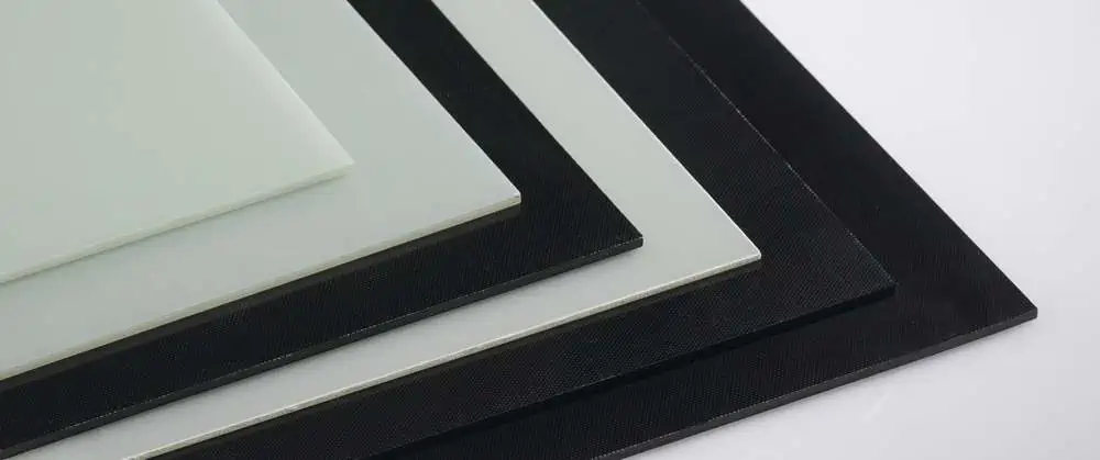
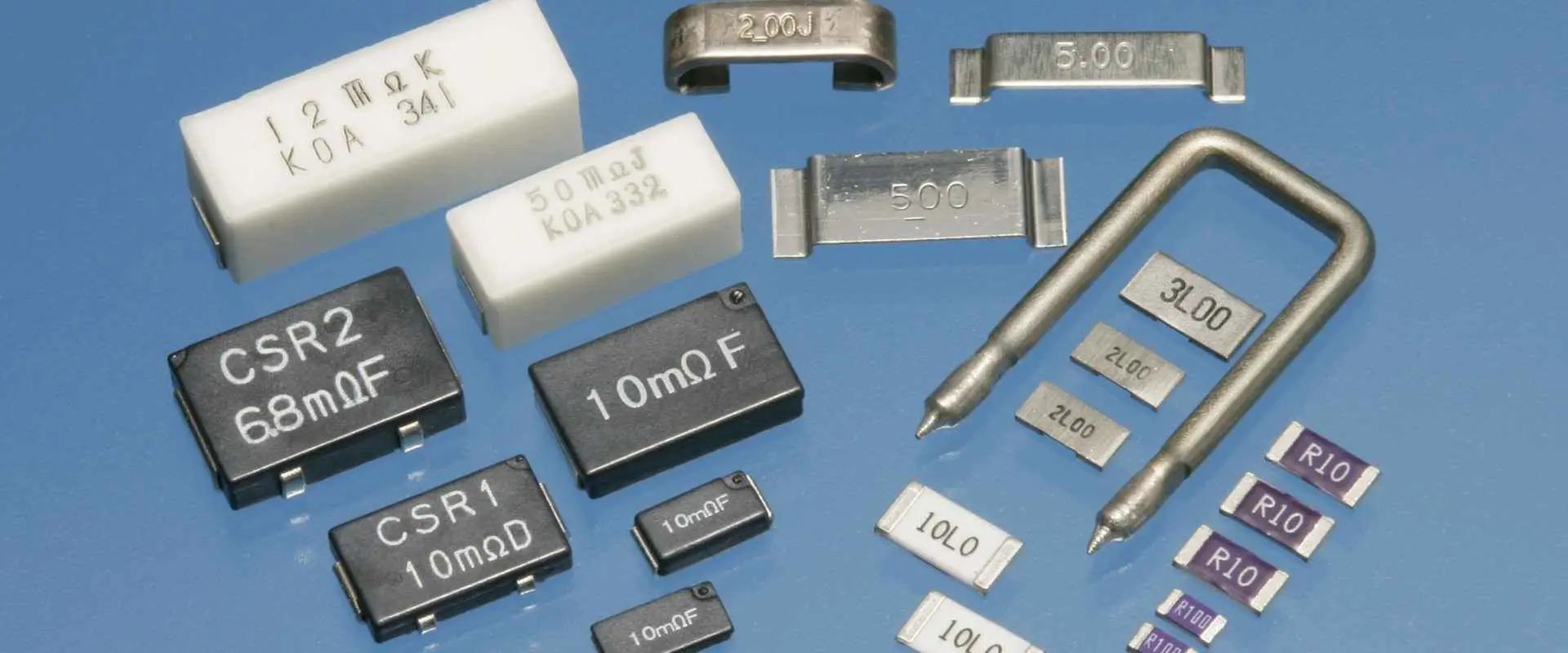
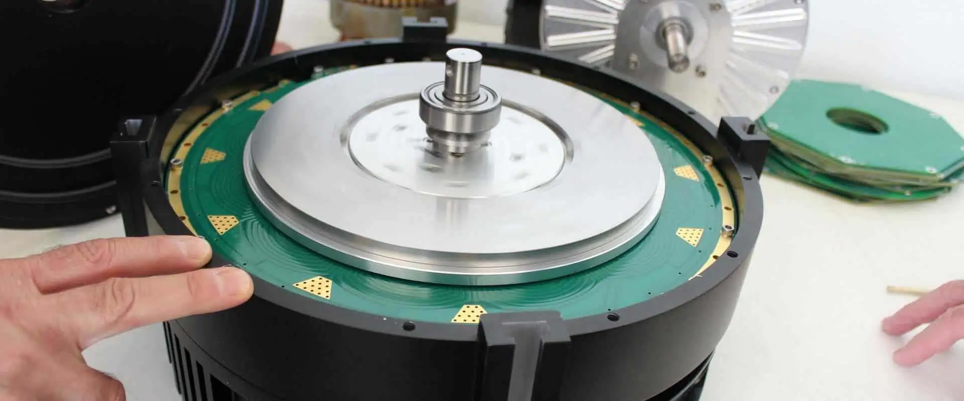
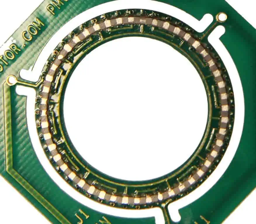
The types of materials and or substrates used in a circuit boardโ€™s construction could greatly impact the performance. In extension, these could increase the chances of the board suffering a loss when signals are being transmitted.

It is therefore, essential to choose the right substrate, especially by considering the appropriate mid loss PCB material to use.

In this section, we aim to introduce you to some of the reasons why the materials chosen for a circuit board might be the reason why the board wouldnโ€™t be able to transmit signals.

The Need for High-Speed Materials

There is a growing demand to reduce the signal transmission issues on PCBs by leveraging on the appropriate materials, especially those designed for high-speed applications.

This is also based on the fact that the type of signal used or required in most high-speed applications is the square-wave signal. Due to the different compositions, it is essential for the materials used for the PCB match the requirements of this signal.

To this end, the circuit materialโ€™s dissipation factor is an important metric for choosing the best high-speed materials.

It is on the basis that the insertion loss of the material is considered. The major considerations are the mid-loss and the low-loss.

On the one hand, the mid-loss insertion loss refers to the substrates of PCB materials that have a dissipation factor of 0.010. Although these types of substrates might be less, the point is that they tend to cause higher insertion losses in the materials.

On the other hand, there is the low-loss PCB material, which has less than 50% of what the mid-loss substrates have. The low-loss substrates have a dissipation factor of 0.005 or lower.

How to Tackle Loss in PCB Substrates

The loss of signals in circuit board materials can be tackled, especially for the high-speed applications. If this must be tackled, then the right dissipation factor must be chosen, as well.

When placed side-by-side, the mid-low and low-loss insertion loss can be used, but the low-loss substrates, based on the dissipation factor, can be favored over the mid-loss. These are some of the reasons supporting the claim:

  • The low-loss substrates with the dissipation factor of 0.005 or less may be preferred over the mid-loss materials due to the fact that it might cause higher insertion loss.
  • To the low-loss materials or substrates will also be preferred, for the high-speed digital designs ranging up to 28 Gbps. In this case, the expected dissipation factor of the substrates should be 0.003 or less.

Can Mid-Loss Substrates be Used?

Yes, you can still use the mid-loss PCB materials, but on the condition that they are used with high-speed digital designs/signals of less than 10 Gigabytes Per Second (Gbps). If the signals are above 10 Gbps, then the low-loss substrates are preferred.

Any Other Option?

Besides the mid-loss and low-loss substrates, one other substrate worth checking out is the ultra-low loss material/substrate. With the dissipation factor of 0.0015 or less, this type of substrate is ideal for the extremely high-speed applications, of up to 56 Gbps.

Key Considerations of Mid-Loss PCB

The rule of thumb is that not all substrates are worth being used for high-speed applications. If you are choosing one for that purpose, then making in-depth research is a must.

a.    Understand the Relevance of Dissipation Factor

The first consideration is to understand the need for using the dissipation factor as a form of โ€œmeasurementโ€ in the first place.

To put it simply, the dissipation factor refers to the circuit board material/substrateโ€™s support for the high-speed digital applications.

This consideration is most important when there is a need to correlate the materialโ€™s substrate to the need for insertion loss considerations in the target applications.

b.    High-Speed Signal Integrity

It is also important to consider the integrity of the high-speed digital signal. The core consideration here is the possibility of the PCB substrate/material to handle analog signals with the millimeter wavelengths ranging between 25 and 100 GHz.

c.    FR-4 or Not?

The Flame Retardant-4 or FR4 material is one of the most-used substrates in the Printed Circuit Board (PCB) industry.

However, you may be unable to achieve considerable success with using it, especially for the applications requiring high-speed signal transmission.

The FR-4 material is not recommended for these applications because of the introduction of distortion and insertion loss for millimeter-wave signals and analog microwave.

How to Choose the Right Loss Tangent for PCB Materials

Rogers RO4533

Seeing how incompatible some of the mid-loss PCB materials can be, it is important to follow a specific procedure to choose one.

Most importantly, the dissipation factor, also called the loss tangent, can be a vital metric for determining the right type of PCB substrates to use.

a.    Choose a Low Df PCB Substrate

The best step is to choose a PCB material or substrate, which has a lower Dissipation Factor or Df. For example, the dissipation factor of 0.005 is the reason why the low-loss substrates are chosen over the mid-loss PCB materials.

A lower Df value helps to reduce or minimize the losses that the high-speed circuits will exhibit after being fabricated on the PCB substrate.

b.    Choose between Performance and Cost

Sometimes, you have to sit down and think of what you really want โ€“ are you opting for performance of the applications or looking to save the costs.

The fact is that the circuit board materials that have a lower Dissipation Factor (Df) are often expensive, while the ones that dissipate the most cost more.

To this end, you are torn between choosing the substrates based on the performances they offer and how much they cost.

Conclusion

The mid-loss or middle loss PCB substrates are not always considered, due to the high Df of up 0.010. This Df value might cause insertion-loss for the high-speed digital signals operating at up to Gbps.

However, you can get considerable advantage if you use the mid-loss PCB substrates/materials for the digital signals operating at less than 10 Gbps.

Understanding Black Core FR4: Properties, Applications, and Advantages

black core fr4

PCBs play an important role in the fin performance of home appliances and consumer electronics. From small to big applications, these PCBs are crucial. You will find different types of PCBs in the market that have specific functions for their applications. One of them that we are going to discuss is black core fr4 because of its versatile nature and the level of feasibility it provides. We will study this special PCB in detail through this post so that you can see why it is important for our applications. 

What is Black Core FR4?

Black core PCB has somewhat the same features as other PCBs that we are aware of today. However, the structure of black core PCBs is different than the rest. One major differentiating factor is the presence of black thermoset resin that positions itself in the middle of two copper foil layers. Now these PCBs are crucial for high power-consuming electronics and for those that rely on consistent heat dissipation.

The purpose of copper layers is to give enough room for the conductance of electrical signals during the process. We don’t have to go above and beyond to produce a black-core PCB. But still, its core is different. We introduce a special black thermoset resin in these PCBs that allows perfect heat dissipation from them.ย 

Characteristics to Ponder When Creating Black Core FR4

There is no doubt that some factors can directly impact the functioning of black-core PCBs. Due to this reason, we have to consider some factors while designing these PCBs to avoid complications. Take a look at these factors below: 

  • Material compatibility 
  • Power distribution
  • Signal transmission
  • Effective heat maangement 

When we talk about such PCBs, heat management comes to our mind. This special property of these PCBs makes them important for heat-sensitive applications. When an electronic consists of black core PCBs, it can tolerate extreme temperatures quite successfully.

Another advantage of black core PCBs is their ability for fine signal transmission so that an appliance can work at its best. There is no doubt that such PCBs comprise sensitive components, and therefore we need to verify if they are working fine or not. It is because later faulty parts can hamper the performance of PCBs on all counts, making them less reliable at the same time. The connection of the core with the PCB parts matters a lot since a strong bond leads to better reliability. Experts suggest that it is beneficial to work precisely on the designs of black core PCBs to make them highly efficient and durable in the long run. 

Why Use Black Core FR4๏ผŸ

If you are someone who has never used black core PCBs, then you might be in need of some reasons that would convince you to give these a try. Well, these PCBs have a sleek design, and many experts consider them stylish as the rest of the PCBs available. Such PCBs can easily resist the components from interacting directly with the light.

We can make it happen by introducing a strong black solder mask that opposes the light coming from the sensors. There is still a chance that the solder can leave out some spaces that can interact with the light as well. If your application is supportive of fr4 material, then using it will greatly reduce the damage. 

Advantages of Black Core FR4

1.    Superior Heat Dissipation: 

Black Core PCB has no parallel in heat dissipation, and due to this reason, we can rely on them for heat-sensitive applications easily. The substrate in them is thermal conductive in nature, which makes seamless heat dissipation possible. We can also reduce the temperature of the PCBs and regulate them by using such a substrate on all counts. It ensures better reliability and makes the entire setup more stable at the same time. 

2.    Durable & Long-lasting: 

The presence of highly durable black core material in such PCBs makes them more long-lasting than the others. From the prevention of cracks to protecting the overall structure of the PCBs, this black core is responsible for making the PCBs more durable in the long run. Due to this reason, powerful and sturdy applications can simply perform better and endure unfavorable conditions with these PCBs as well. 

3.    Good Transmission Performance: 

Black Core FR4 shows better signal transmission performance because it consists of a low dielectric constant. With this material, we can ensure less signal loss and technical problems during signal transmission. Therefore any application that constantly works with signal transmission can procure great advantages from black core PCBs on all counts. Plus, the heat produced due to frequent signal transmission can be easily regulated with these PCBs to a large extent. 

4.    Stunning Appearance: 

These PCBs have a stylish design as compared to the others. Due to this reason, these can easily blend with different electronics and enhance their appearance as well. The copper traces in these PCBs are also hidden that do not give an off-look at all. The black surface completely covers the wires and specific components, which adds to its structure easily. Even in the case of open electronics, you can easily visualize the PCB component due to fine arrangement and proper adjustment through design. The best part about the black core is that it blends well with the PCB parts and does not ruin the appearance of the applications at the same time.ย 

Creating the Black Core FR4

BLACK PCB

In this last section, we are going to see how to produce a black core PCB in simple steps. 

  • We start with the layout development or design of PCBs. We can rely on different PCB designing tools available. 
  • Moreover, we then use a laser printer to take printouts of this design on a thin piece of film. 
  • The next step is to fully clean the copper board. Do this by using a cleaning agent to exclude dirt to transfer these printed designs to the board. 
  • It is important to optimize the heat and pressure while transferring these designs onto the boards on all counts. 
  • The next step is to etch the boards. It will exclude the extra copper since we do not need+ it further in the process. 
  • Now we need to drill the holes for both vias and holes. These are a crucial part of the PCBโ€™s structure. 
  • The next step is to combine the resin layer and the copper layer together by supplying them with the appropriate amount of heat and pressure. 
  • We then bake the boards in an oven so that an unbreakable connection can develop between the layers easily. 
  • The second last step includes the solder mask. It enhances the bond between the components and layers present in the structure. 
  • Finally, we use a silkscreen layer to label the boards to avoid complications in patching and shipment. 

What does D-code Mean in Gerber

gerber D-code

Gerber files are important in the technical fields, and we can avail many benefits from them as well. Today Gerber files are important. We can fully rely on them in the field of PCBs, which gives us a helping hand for the development of industrial PCBs. For these Gerber files, D-code and coordinates are important. We need to rely on the photo plotting technique to regulate the sketches of solder pads

In the old times, Gerber files majorly had two formats, including RS-274-D and RS-274-X. Their roles are also different. RS-274-D works on isolating the coordinates from the D-codes. Whereas the RS-274-X depends on combining the D-codes and coordinates into a single file with other factors ad attributes. It includes custom D-codes, polygon filling, positive/negative image combinations, and much more. There is no doubt that without Gerber files, we cannot maintain precision in the field of PCBs. With these files, we can also attain more accuracy in the PCB data and design specifications on all counts. We are going to highlight D-codes in Gerber files in this post. 

Introduction to Gerber Format:

Gerber is a standard file format that has common usage in the technical fields of electronics and PCBs. Besides, these are useful for organizing the data and specifications of PCB designs so that the seamless development of PCBs can take place later through production. 

Through Gerber files, we can easily fabricate the PCBs, determine the PCB layers, assemble the accurate components, hole sizes, length of copper traces, and much more. In short, Gerber files are important when we are considering details and precision work regarding PCBs. 

Understanding D-codes:

D-codes are the fundamental blocks of a Gerber file, and without them, we cannot fully make these files work at their finest. Basically, D-code is a special numeric identifier that relates to a particular sketch of the PCB layer. Now every layer represents some specific information, and to easily access them, we can use D-codes as their identifier. With these D-codes, a producer can quickly use information regarding a specific layer on all counts.ย 

D-code & PCB Layers:

There are different D-codes that we need to consider regarding Gerber files. These are different in terms of their roles, and it is better to have a look at them to understand the role of D-codes in Gerber files completely. 

  1. D01: Top Copper Layer: This layer consists of all the mounted PCB parts and other sensitive components of PCBs. 
  2. D02: Bottom Copper Layer: This layer houses conductive routes and develops connections between the PCB parts on the whole. 
  3. D03: Solder Mask Top: This layer is important because it makes sure that the solder mask completely covers the components and also develops strong bonds without undergoing solder bumps. 
  4. D04: Solder Mask Bottom: It contains a protective solder mask for the upper D03 layer. 
  5. D10: Drill Holes: It gives information regarding the positioning of drill holes and vias. 
  6. D20: Top Silkscreen: This layer helps in labeling and marking PCBs for the top layer, which helps in final assembly on all counts. 
  7. D21: Bottom Silkscreen: Just like information for the top layer is important, we have this layer that helps with the labeling of the bottom layer. 

Importance of D-code in PCB Manufacturing:

Following are the major benefits that D-codes provide us with each time: 

  1. Clear Identification: With D-codes, we can easily rely on quick and clear identification of PCB details, design specifications, and component positioning in all circumstances. 
  2. Layer Differentiation: Since PCBs have multiple layers that have different functions, we can exclude confusion and mishandling of these layers by adhering to D-codes for proper management. 
  3. Accurate Reproduction: Accurate reproduction of PCB design is clearly easier with the help of Gerber files because D-codes make it possible for the producers. 
  4. Streamlined Production: A producer can easily streamline their PCB production process with the help of D-codes by avoiding mishaps to a large extent. 
  5. D-code Versatility in Multi-layer PCBs: You might not believe that D-codes are also good with multilayer PCBs, where they make their assembly and organization much easier for the producers. Moreover, multilayer PCBs are complex, and we can use D-codes to simplify positioning vias. It also develops strong electrical bonds between them easily. It will help us with the fortification of signal integrity, and there will be fewer chances of interference as well. 
  6. Customization and Manufacturing Flexibility: When we consider D-codes, we can ensure more customization and production flexibility for PCBs. There is no doubt today; producers are relying on D-codes. So that accurate execution of intricate details can take place in the case of complex types of PCBs. From impedance control to signal routing and power distribution, there is nothing that D-codes cannot provide us with information with. 
  7. Efficient Communication: With D-codes, it is obvious that we can see efficient communication taking place between designers and producers. So that a fine PCB can later be developed without any faults and errors. D-codes are important in this regard because every department can bring out precision in PCBs by sticking to the information given by these D-codes in Gerber files. 

Conclusion:

Gerber files are huge assets for technical producers to enhance the efficiency of their products and develop precision PCBs. One of the main aspects of Gerber files is the D-codes that we have discussed in this post for you. D-codes are your key to reducing errors in your PCB designs and establishing effective communication between different departments. From making PCBs accurate to providing them with different features, D-codes play a crucial role in the field of PCBs. We hope that now you can simply adhere to D-codes in a better way for your future projects. 

How to select resistor and capacitor components for PCB design

SMD Resistor

Two components of a PCB that are crucial in its structure are resistors and components. Their roles are essential to developing the finest industrial PCBs for safe and seamless electronics performance on all counts. If we rely on faulty components, including resistors and capacitors, there are more chances of complete PCB failure

We will see how we can pick the suitable component for the sustenance of our PCBs through this post. After this, you will be able to select the appropriate capacitors and resistors for your PCB projects successfully. 

Selecting resistor components for the PCB

First, letโ€™s see how we can choose suitable resistors for our PCBs. As you know, the purpose of a resistor is to oppose the current flow through a circuit or a setup. Therefore, we can use them in a PCB to regulate the current flow easily. Letโ€™s see what factors you need to evaluate your options for picking the right resistor!

ยท       Tolerance level:

Tolerance is an important factor for resistors. The best resistors are those having tolerances of 0.1%, 5%, and 10%. The reason is that we can easily work with these tolerances without facing any complications. Some experts even compare these three specific tolerances and emphasize using a tolerance of 0.1% for the projects. Some resistors that have high tolerances are cheaper than others. 

ยท       Power level:

There is no doubt that some resistors are not good in terms of power level. Therefore, for PCBs, we need to rely on powerful resistors that can perform their job under unfavorable situations easily. Inappropriate resistors in the aspect of power level can directly damage the PCB as well. It is always better to determine the power level of the resistors beforehand when buying them. 

ยท       Temperature:

The temperature range of resistors also differs. We need such resistors that can easily tolerate high temperatures if PCBs are working in heat-sensitive applications and devices. It is better to see what type of temperature range you need by comparing the resistors with your applications. It will protect your PCBs from undergoing heat damage and will enhance their longevity as well. 

ยท       Resistance:

Another important factor is resistance. The best resistors in this aspect are those with 1-kilo ohms. These can make PCBs more efficient in terms of performance and durability. Make sure to check the resistance before picking the resistors. 

Selecting capacitor components for the PCB

Now it’s time to see what factors make a good capacitor. Carefully follow the section below to see how you can never go wrong with the capacitor selection each time. 

ยท       Tolerance:

Every capacitor has a different tolerance, and good capacitors are those that come with a maximum 20% tolerance. Well, if you find one with a 10% tolerance, it is good enough. It is better to check the tolerance of capacitors to avoid all sorts of complications easily. 

ยท       Capacitance:

The default and suitable capacitance of a standard capacitor is 10uF which is why we need to rely on such capacitors on all counts. Chances of failure and poor performance with such a capacitance are fewer. 

ยท       Voltage level:

The capacitors are not good at tolerating high temperatures due to voltage changes. Therefore, you need to see what type of capacitor suits your projects the best to avoid failure and risks. The best way to do this is to seek professional help to avoid confusion. 

ยท       Temperature range:

The capacitors that can tolerate up to 85 degrees have an optimum temperature range, and therefore, experts always emphasize their utilization as well. Make sure to use such a capacitor to drive positive results. 

Factors to Consider while Selecting Resistor and Capacitor Components for PCB Design

You don’t want to ruin your projects by relying on faulty resistors and capacitors. Therefore, to give you a certain direction, we have compiled some effective tips in this section for you. Below are some handy considerations that can greatly help you in this regard. 

  1. Component Values: The component values like current needs, voltage changes, time constraints, and impedance are important to determine when it comes to capacitors and resistors because these are variable factors. Therefore always fix them as per your projects for better results. 
  2. Identify Tolerance: Two factors, including power rating and tolerance, are important for the fine performance of resistors and capacitors. Tolerances for resistors are optimum if you’re using 1%, 5%, and 10%. Tolerances for capacitors work best in 5% and 10% only. Power rating is important to determine because, through this, we can execute damage control and seamless power dissipation with it to a large extent.
  3. Select the Right Size: It is better to understand the importance of package size since these are different for resistors and capacitors. First, check PCB designs and see which components are a perfect fit as per your designs. Inappropriate package sizes can easily ruin PCBs through short circuits. Experts believe that going with SMD components, in this case, is beneficial. 
  4. Temperature & Environmental Requirements: Not all resistors and capacitors are good with temperature regulation and preventing environmental damage. You happen to work on some applications that need extra features like moisture absorption and vibration. Therefore always choose the types that are suitable for your projects. 
  5. Voltage & Current: Another important tip here is to determine the voltage and current ratings. It is crucial that resistors and capacitors of your choice work under a fixed limit of current and voltage. If these will cross this threshold, it can lead your PCBs to complete failure. 
  6. Signal Frequency: When it comes to the selection of PCB components like resistors and capacitors, signal frequency and capacitor ESR are crucial. ESR is important for RF applications that operate on a high frequency. It prevents signal loss and also makes the setup efficient. 
  7. Research Specialized Components: There are some special projects that need advanced components like high voltage capacitors and some technical components having advanced filtering attributes. Due to this reason, it is better to carefully determine your needs and see if you actually need such specialized components or not. 
  8. Cost & Availability: Some capacitors and resistors having advanced features are costly. There is always a chance that these might not always be readily available in the market. Therefore, make sure to look for suitable and affordable components to not spend extra on your projects. 
  9. Check Supplier Datasheets: Another great tip for you in this regard is to check manufacturer datasheets. These are important and give you a clear idea about what type of resistors and capacitors you need to rely on for your projects. 
  10. Prototype & Test:ย A handy trick here is that when you are buying resistors and capacitors, then always test them on a prototype of your actual PCB to see if they work on it as you desire or not. This eventually saves you from loss of investment and reworking.ย 

Tips for Selecting Resistor and Capacitor Components for PCB Design

Resistors
Resistors

ยท       Component Footprint Conclusions

Today, PCB producers have to pay heed to the component footprint decisions. In this way, producers will be able to determine land patterns at the same time. Always relying on prints that are similar to the land designs is beneficial. You can use datasheets for this purpose to omit the chances of errors and faults greatly. 

ยท       Good Grounding Techniques

Make sure that the ground planes are in an accurate position in the setup because these are one of the most important PCB parts. We can combine ICs with capacitors to make the setup more efficient in its performance in the long run. For grounding purposes, it is better to check the size and frequency of the capacitors. 

ยท       Guarantee to Have Complete BOM Data

It is crucial that you consider the BOM, which is the bill of materials. So that you can evaluate your expenses on all counts; in this way, you will be able to prioritize your investment and only rely on much-needed PCB parts on all counts. Therefore considering BOM data always comes in handy when producing PCBs on a commercial scale. 

ยท       Check Spare Gates

Another good practice that you can follow is to check the spare gates. These gates work as barriers to provide a seamless pathway for combining the input with its corresponding signals. This step completely prevents floating. Spare gates are important for your setups because you can ensure efficient performance through them successfully. 

ยท       One Pad For One Connection

Follow the one-pad-for-one connection approach. It eventually helps with the seamless PCB component arrangement and makes the assembly flawless. The pads must be of suitable sizes, and if not, you will have to face complications in the process of soldering PCBs later. 

ยท       Component Package Choice

Always determine the package size for your projects. You cannot adjust large components in a small PCB and vice versa. Therefore package size determination is crucial in this regard so that you can avoid complicated PCB development easily. 


Recap!

We hope that now you can choose the perfect capacitors and resistors for your future projects. After reading the important factors that help you pick the right resistor and capacitor, you will be able to reduce the chances of failures and risks for your PCBs from this day forward.  

Decoding the Puzzle: STL vs. 3MF File Format Comparison

STL vs. 3mf file format

Stereolithography, also called standard tessellation language, is a technology that has been in use for many years. The purpose of this tech is to use CAD data and translate it with the help of a 3D printing device. Over the years, different upgrades in technology have made it a crucial development for the sustenance of futuristic devices and components for all of us. 

There are different aspects of STL that we need to consider while learning about it. This tech is important for translating complex data and developing different types of complex geometrical objects. One thing to remember is that we cannot use STL for mesh topology. The reason is the files are too big to handle for a regular 3D printer

There are also more chances of errors and faults that can become irreversible if we do this. You will find different companies today that are relying on this tech for daily operations. Data formatting and modeling are easier with this technology as well. Another way is the 3mf file format. It means you can use it for individual object development with the help of the old mesh. 

This way is beneficial when you want to reuse the single mesh for the development of multiple objects later. STL vs. 3mf file format can be hectic for beginners. Therefore we are going to assist you in picking the correct method in this post. Letโ€™s get started!

STL (Stereo Lithography):

  • Structure of File: STL files mostly have triangular facets that are important for the development of 3D geometries. The objects are just a group of mesh that achieves a shape later in the process. 
  • Simplicity: STL has always been one of the most feasible techs that support 3D printing; therefore, for both beginners and experts, this process is easy to rely on. 
  • Compatibility: STL is also compatible with printing purposes and file management, and development with STL is also easier for crafting complex objects. 
  • Limitations: STL still has some limitations in the form of colorless files and the texture of the objects under development. The STL process is not handy for the development of complex geometries that contain multiple colors at all. 
  • File Size: STL files are always larger than 3mf files because these contain all the insights and details regarding a 3D object under development. 

3MF (3D Manufacturing Format):

  • Structure of File: 3MF files are more critical than STL files because these are exceptional for displaying complex data for multiple objects. From color details to material insights and information regarding the texture used, 3mf files are a good choice when you want to go deeper into geometrical objects. 
  • Versatility: 3MF files are good when we are aiming for 3D objects that contain multiple materials and complex formations. You can even use a single 3mf file for this entire representation in an organized manner. 
  • Compression: 3MF files are compressible, which means that we can reduce their sizes which does not create a load on the system, and it comes in handy when we are dealing with huge complex data. 
  • Enhanced Support: It is important to consider that 3mf file formats are supportive of different types of 3D printers, but problems can still occur during this pursuit. 
  • Standardization: The 3mf file formatting is always undergoing changes to meet the industry standard of 3D printing to exclude the chances of error as much as possible. 

Use Cases:

We are now going to take a look at the major use cases of STL vs. 3mf file format. You can see which option suits you the best based on your requirements and the nature of the projects. 

  1. STL:ย STL files are suitable when your 3D objects are simple and do not require extensive representation of data and insights. You can use STL when you are not working on the color and material of the objects. The applications of STL include rapid manufacturing, modeling, feasible visualization, and flawless prototyping.
    1. 3MF: 3MF files are for intricate 3D objects and are larger in size because of the range of data they represent. This file format is handy for applications. There are chances of data manipulation, and a fine representation of the materials used matters a lot. Architectural models and technical objects can benefit a lot from this format. 

Characteristics of STL files

There is no doubt that STL files are important because of their remarkable characteristic of small-volume complex data and mid-range intricate object representation. Their range of characteristics makes them a reliable choice to merge with 3D printing to gain great results. You can even use CAD with STL files easily. 

These are crucial when you need quick prototyping when your deadlines are approaching. The process comprises triangles and displays the data by using these triangles. In this way, we are able to create simple to little complex objects easily with the help of STL files. 

The number of triangles we are working with directly determines the precision of the objects we are going to 3D print. This technique leaves no margin behind in developing the exact same object that matches the model on all counts. The difference between STL vs. 3mf file format is that in STL files, you don’t get in-depth information about color texture and materials used. This is possibly one of the biggest downsides of STL files. Speaking of which, we have to know about another drawback of STL files which is the higher chance of corrupted files. 

If you happen to interact with a corrupted file, you cannot use it further. Instead, you have to rework it, which is also time-consuming. There is still some external help present that makes your reworking easier. Another drawback is you, as a human, cannot read these files; instead, you need to rely only on software for reading purposes.ย 

Characteristics of 3MF files

There is no doubt that today’s 3mf file format is common because of its remarkable properties. It makes your projects much easier to complete, no matter how intricate they are. You can fully adhere to the principles of 3D printing with the help of 3mf files without any complications. 

With 3mf files, you are able to consume data effortlessly since these barely undergo glitches and file mishaps. You can compress huge amounts of data and in-depth information regarding a project in a single 3mf file for later usage. Now don’t mistake a 3mf file for a mesh-like STL one. These are mostly zip files that you can for referring to the 3D modeling and use the data stored in them for the model development. From colors to materials and much more, you can easily rely on these files for different advantages. 

The latest features of 3mf files will also make your current projects much easier at the same time. With 3mf files, prototyping, and 3D printing is never a hustle, even for beginners. Unlike STL files, these are human readable, which omits the need to use external help and third-party software for this purpose. 

Advantages of STL vs. 3MF File Format

If we talk about 3mf files, these are your go-to option to store tons of crucial data in a single file. These are beneficial when we are working on complex models and 3D objects. Later, you can develop similar models with the help of 3D printing and rely on the information delivered through these files quite feasibly. Things are not easy with STL files because these are impossible to read manually, and we need to use different software for this. Plus, we won’t get the basic information regarding the 3D objects since the texture and color details are absent in STL files. 3mf files are handier because, with these, you can make embedding possible and modifiers that can exclude the obstacles in your way of 3D printing. You can use your copyrights for the models and designs with these 3mf files as well. These files are important because they offer you a higher degree of customization on all counts. 

Conclusion

There is no doubt that we have to struggle with making a decision between STL vs. 3mf file format. However, we have shared all the crucial information regarding these file formats with you in this post. So that you can easily decide what you are going for in the future.

One thing that is always going to help you in this regard is evaluating your options. The better you will be able to do that, the soon you will realize what type of file format will prove to be beneficial for you. 

Functions and Benefits of the PCB Stator Motor

PCB Stator

A stator serves as the heart of an electronic motor. This equipment is usually made of iron and it goes around a stationary part. The weight of a stator accounts for two-thirds of a motor. In order to reduce the weight of the stator, professionals recommended making the stator from a PCB.

Over the years, the PCB stator has gained a lot of popularity. The unique benefits and advanced performance of this stator makes contributed to its widespread use. Also, it is a better choice compared to conventional copper wound machines. Furthermore, the PCB rotor motor technology is beneficial for several applications. It offers effective solutions in some applications, thereby contributing to the performance of these systems.

There are several questions yet to be answered about the PCB stator motor. How does this equipment impact electronics and what is the difference between the stator and conventional copper wound machines? This article provides answers to all these questions.

What is a PCB Stator Motor?

The printed circuit board stator motor features conductive traces. Rather than the conductive traces, copper wires were used in conventional machines. With the PCB stator design, it was easier to precisely place conductive traces. Therefore, this contributed to the increased efficiency and enhanced performance of the PCB stator motor.

The use of copper wires in conventional machines has its limitations. To prevent such limitations, the PCB stator integrated the circuit board technology to maximize copper placement in the stator. In this case, the copper is only placed where it is required. As a result, we now have more efficient machines that only require a proportion of the copper.

PCB stators are available in a wide range of sizes and shapes. Therefore, it is well-suited for many applications. In a PCB stator, the copper coils are directly etched on the circuit board. The use of copper coils reduced the weight and size of stators.

Asides from reducing the weight and size by half, copper coils helps in getting rid of cogging, eddy current losses, torque ripple, and stator hysteresis. In the long run, this leads to an improved efficiency across many load conditions. Furthermore, the PCB stator makes automation much easier during the manufacturing process.

Specialized winding machines are often needed for the production of conventional copper wound stators. These machines are very expensive and complex to operate. On the other hand, PCB stator manufacturing doesn’t need these machines. This makes PCB stator a cost effective option.

Benefits of PCB Stator Motor

 Stator PCB Board
Stator PCB Board

The PCB stator motor offers a durable and compact solution for a number of applications. With several benefits, this equipment has been found useful in high-performance applications.

Efficiency

One of the factors that contribute to the popularity of the PCB stator motor is its efficiency. It can produce a more powerful magnetic field due to its less resistance. PCB stators don’t need much energy to function well. With this, the battery life in devices can be longer.

Size and weight

Since PCB stators don’t have big metal components, they are lighte weight and very small in size. Therefore, they are suitable for use in applications where weight and space are a major concern.

Durability

Epoxy coating and metal laminations can cause mechanical failure in equipment. The absence of these things in a PCB stator motor helps to reduce the risk of damage and mechanical failure in stators. Furthermore, PCB stators are less prone to environmental factors and corrosion.

Precision control

This is one of the best benefits a PCB stator motor offer. It gives the user a better control of the operation of the motor. Also, this is beneficial for applications that need good motor control. Such applications include drones and robotics.

Better Flexibility

In order to achieve increased flexibility, a PCB stator is a much better choice than a copper wound stator. This is because you can place copper where it is required in a board. Also, you can construct PCB in several shapes.

Quiet Operation

PCB stator motors have fewer moving parts which makes them quiet while working. Also, they don’t vibrate while in operation.

Sustainability

PCB stator needs only a small fraction of copper and produce motors that use less energy. The motor design’s sustainability increases due to the PCB stator.

The Working Principle of a Stator

Every generator or motor features a stator. The stator is a heavy iron that comprises copper wire. The iron copper stator has been replaced by the PCB stator. There is a low amount of copper present in the PCB stator. This resulted in smaller and lighter weight stator.

Generally, a stator has a 3-phase supply which helps to produce the rotary magnetic field. However, this function will change according to machines such as generator, motor, and devices powered by fluids. The stator produces a rotary magnetic field in the motor. In a generator, the rotary magnetic field is changed into electric current. The stator directs how fluid flows to the rotating part of the system in fluid powered devices.

Eddy current losses are one of the problems associated with stators. However, there are ways to prevent or reduce such problem. The stator can be designed with quality alloy steel laminations. For a conventional wire wound stator, the integral parts of include the outer frame, core, and windings.

The PCB stator technology helped to create axial flux electric motor for electrification. With more development in the PCB stator technology, much has been achieved.

What is the Difference Between the PCB Stator and Traditional Electric Motor?

The PCB stator has replaced the use of the traditional electric motor. In a PCB stator motor, there are no copper winding and external iron. In this case, a single circuit board comprises copper circuit. This helps to minimize the loss of energy that occurs due to the core.

Furthermore, the PCB stator motor enables sensors and some electronic components to be directly installed on the circuit board. As for traditional electric motors, the components are mounted separately. The PCB stator ensures better efficiency than a regular electric motor. In terms of weight, there is a difference between the PCB stator and traditional electric motor. The PCB stator has a lower weight compared to the traditional type.

Due to the reduced weight of the PCB stator, it can get rid of torque ripple. Furthermore, the PCB enhances the insulation properties of the copper. This helps to prevent any possible short circuits or other failure. One of the benefits of the PCB stator is its cost effectiveness. It is a cheaper alternative to the traditional electric motor.

There is noise reduction and extension of the drive system lifespan. PCB stator motor has been used in applications ranging from medical pumps to robotics.  Thermal dissipation is a major concern when it comes to the utilization of PCB stator. PCB stator has more surface ratio than a copper wire stator. Therefore, this enables better thermal dissipation.

With a larger surface ration, there is better thermal dissipation; hence, less copper is needed. Some of the key benefits of using PCB stator are cost reduction, reliability, greater efficiency, and weight reduction.

Functions of a Stator

There are many uses of a stator. A stator plays functional roles in a wide array of applications.

  • A stator acts as a field magnet in a motor. This function is according to the rotating electromotive device.
  • It is also used in a motor to provide a magnetic field
  • It transforms the revolving magnetic field to electric current when used in a generator
  • The stator creates motion by interacting through the armature.
  • It directs the fluid flow to the rotary system when used in fluid-powered devices.

PCB Stator Manufacturers

ECM PCB Stator Technology

This companyโ€™s innovation has eliminated the use of copper winding in conventional electric motors. Its ultra-thin stator offers enhanced efficiency at minimized environmental impact. ECM PCB stator can withstand extreme environments. This lightweight stator provides no cogging and noise. Their PCB stator design is beneficial to the electric motor industry.

Infinitum Electric

The objective of Infinitum Electric is to develop high-end stator technology for smarter electric generators and motors. Its PCB stator technology is developed to provide unmatched durability and efficiency. The company which was founded in 2016 has been able to achieve great improvement in the operations of PCB stator. Also, their PCB stator has no copper windings which are usually present in the regular electric motors.

Conclusion

For more than several decades, electric motors have continued to evolve. Before the PCB stator came into the picture, the bulky copper wire stators were commonly in use. In such stators, the copper interacts with the magnet to create speed and torque. However, these stators need copper wire winding.

The PCB stator motor is a better alternative to the traditional electric motor. For better flexibility, a PCB stator is better than a copper wound stator. We have discussed every vital detail about the PCB stator in this article. Also, we compared the PCB stator with the copper wound stator.

How does LiDAR for Raspberry Pi Work and does it Offer Solutions?

Lidar for raspberry pi

Essentially, LiDAR can be described as a ranging device that measures a distance from a target. This distance can be measured through the sending of short laser pulses as well as recording a time lapse in-between the light pulse (outgoing) and the reflected light pulse (back-scattered) detection.

Furthermore, the LiDAR system might make use of multiple laser beams, scan mirror, as well as other means fir scanning an object space. Furthermore, with ability to offer precise measurement of the distances, this raspberry LiDAR could be utilized for solving many problems.

For remote sensing, the raspberry LiDAR systems are utilized for the measurement of absorption, scatter, as well a re-emission from molecules or particles inside the atmosphere. Due to these purposes, these systems might have some requirements on the laser beamsโ€™ wavelength. A molecular speciesโ€™ concentration in our atmosphere can also be measured. In addition, rain droplets inside the atmosphere could be measured in order to estimate a stormโ€™s distance as well as the rate of rain fall.

The remaining LiDAR systems offer profiles for surfaces of three dimensions in object spaces. For these systems, this laser beams wonโ€™t be tied onto spectral features. Rather, the laser beamsโ€™ wavelength might be selected so as to make sure of safety to the eyes or prevent atmospheric spectral characteristics. This probing beam will encounter and would be reflected buy the โ€œhard targetโ€ and back into the LiDAR receiver.

Also, raspberry LiDAR could be utilized in determining a targetโ€™s velocity. This could be done either via the Doppler technique or through the measurement of the distance to the target in quick succession. Take for instance, atmospheric wind velocity as well as an automobileโ€™s velocity could be measured through the LiDAR system.

What Challenges Does LiDAR Face?

Raspberry pi Lidar
Raspberry pi Lidar

LiDAR faces some challenges with the operational LiDAR systems. These challenges are dependent on the LiDAR system type. Below are some examples and instances.

The isolation as well as rejection of the signal out of the emitted beams

Generally, the probing beamโ€™s radiance is much greater compared to that of a return beam. You must take care to ensure this probing beam isnโ€™t scattered or reflected by the system and into a receiver to the extent that the detector becomes saturated as well as unable to detect the external targets.

Also, spurious returns coming from the debris inside the atmosphere in-between the intended targets as well as the transmitter. This debris may cause strong spurious returns, to the extent that these intended targets arenโ€™t detected reliably.

Other Challenges of LiDAR for Raspberry Pi

Limited optical power: Systems having more power inside the beam offer greater accuracy. However operating it is costlier.

Speed for scanning: Safety could become a problem when the source of the laser operates at a frequency, which is dangerous to the human eye. The problem is mitigated with other approached like flash LiDAR that illuminates large areas at once and operating at wavelengths that are safe for the human eye.

Device cross-talk signals coming from closeby LiDAR devices may disturb the signal. Now, the challenge is to differentiate between the emitted signals by the closeby raspberry LiDAR devices. Different approaches with the signal isolation and chirping are still developing.

Maintenance and Cost of the LiDAR systems: The systems are expensive compared to alternative sensor types. However there have been developments in overcoming high costs as well as produce systems at reduced price to ensure wider use.

Rejecting returns from the unintended objects: It is similar to rejecting atmospheric spurious signals as previously mentioned. Moreover, this could also take place in scenarios of clear air.

Finding solutions to these challenges involves reducing the beamโ€™s size at different target distances and over the received field of view at your LiDAR receiver.

Applications of LiDAR for Raspberry Pi

The areas for application for the LiDAR are varied and deep. For atmospheric sciences, the LiDAR is utilized for detecting many atmospheric constituents. Also, it has been utilized for characterizing aerosols inside the atmosphere. In addition, it helps to investigate the upper atmospheric profile clouds, winds, allows weather data to be collected as well as several other applications.

For astronomy, LiDAR is utilized for measuring distances. This serves both near objects and distant objects. The fact is, LiDAR is an important device for the improvement of the distance measurement onto the moon as well as to millimeter precision. Also, LiDAR is important for creating guide stars for different astronomy applications.

In addition, the topographic LiDAR makes use of the near-infrared lasers to map the buildings and lands. The bathymetric LiDAR makes use of water-penetrating green lights for mapping the riverbed and seafloor. In agriculture, you can use LiDAR for mapping crop growth and topology. This can give information on the irrigation requirements and fertilizer needs. Concerning archaeology, LiDAR is used for mapping ancient systems for transportation under the thick forest canopy.

More on Applications of LiDAR for Raspberry Pi

As of today, LiDAR is utilized in creating three-dimensional models of the worlds all around the LiDAR sensor for raspberry pi. One application which makes use of the point cloud that is created by the LiDAR system is autonomous navigation. The miniature LiDAR systems could even be seen in small devices like mobile phones.

LiDAR for raspberry Pi has one great application, which is the situational awareness of our autonomous navigation. These situational awareness systems for moving vehicles should be aware of the moving and stationary objects around them.

Radar has been utilized for long for detecting aircrafts. Also, LiDAR for Raspberry Pi is very important or terrestrial vehicles. This is because of its ability to tell the distance to the objects and is extremely precise when it comes to directionality.

This probing beam could be directed to the precise angles and then quickly scanned to create point clouds for this three-dimensional model. This ability to scan very quickly is important for the applications since this is a very dynamic situation.

LiDAR for Raspberry Pi Robots

Raspberry Pi 4 vs 3

The autonomous raspberry pi robots help in navigating their environments without having to bump into things. Making use of the ultrasonic sensor like the HC-SR04 in detecting obstacles is a common tool for the Pi-based cars and robots. However, this car project, which is created buy a developer and maker, is going further by mapping a room out using the LiDAR sensor raspberry pi.

At its core, this car features the Raspberry Pi 4 4 Gigabyte. As the car is on motion, the LiDAR sensor raspberry pi data will be transmitted from the Pi and into a PC close by, which makes use of the simultaneous mapping and localization system in creating the virtual, 3D replica of the room that surrounds the Raspberry P. Also, this program provides the carโ€™s virtual representation in unity for estimating its position inside the room.

Understanding the Raspberry Pi2 and LiDAR

Though I have given up when it comes to SRR contest, have great interest in robots. Lidar serial interfaces formed a great match to the Raspberry Pi because both of them functions at the 3V3 levels. With this, it gets rid o the USB interface. Similar efforts were put in 2014 by Thomas Jespersen who made use of the STM32F429 board, then created a Lidar video while in action.

The Lidar Physical

Lidar can be described as any sealed unit having a hanging motor from one of the ends. This motor helps in driving a turret which rotates at about 300 rpm. This turnet has the laser in it and receives sensors and through spinning, it offers a scan of 360 degrees of the area. This receive and laser sensor features two optical ports from the turret.

Two short cables having JST connectors that come from the LiDAR are present. The two-pin connector functions by providing power to the motors. Also, the four pin connectors give a power of 5V to its control circuits as well as the serial interface of 3V3.

The pinouts include the motor cable, whereby the ground is black in color, while the PWM or 3V3 is red in color. For the interface cable, the red color has 5V, the orange color is TX, while the brown color is RX.

For the vacuum, the powering of the motor is done by a source of 12V. This is possible by using the PWM at about a duty cycle of 25 percent. This indicates that the motor requires about 3V in order to operate at the proper speed. This eventually came to be true after subsequent testing.

Furthermore, the board for the USB interface runs this LiDAR from an input of 5V from your USB connector making use of the PWM controlled with the help of the proportional integral differential (PID) loop in order to maintain the speed of the motor.

Why make use of PID and PWM?

In order to be able to maintain an RPM that is constant for spinning turrets as it collects dirt, other detritus, dust, and wears, PWM and PID is used. During testing, it was noted that this motor would turn this turret in any of the directions depending on the negative and positive connection. Still, this interface works effectively; however, there would be a reversal in the data pointsโ€™ sequence. Usually, this turret turns in a counter clockwise direction.

Hereโ€˜s an advice. Inside some earlier units, this interface made use of 3V3. Therefore connecting them to the 5V might destroy this interface. Our initial hook-up between the LiDAR and Pi was dirty and quick. We connected this motor to the 3V3 output of the raspberry Pi and it worked. This output gotten from the Raspberry Pi 3V3 is simply limited to the 50 mA, through the LiDAR and the specifications. According to Wiki, the motor ought to draw about 64 mA. However, we measured ours and it drew more.

The LiDAR Software

The next thing is the creation of some software so as to understand the way this works. The fact is, we made use of C++, so we installed the Raspberry Piโ€™s tool chain and sicove4e that the compiling speed is enough for development. We started making use of the programming editor (Geany). This is a setup I leant when working with a Python code for this LiDAR.

Also, it handles many programming languages and we have chosen it as the general purpose text editor on Raspian and Ubuntu. However, we eventually stopped using Geany and then installed the Eclipse CDT on Raspberry Pi. We did it when we discovered that it couldnโ€™t reformat the C++ code properly after editing. Also, we discovered that Eclipse works wrll on Raspberry Pi. However, during our work, we were disappointed with the switch. This is because, while working with Geany, we were re-learning ways of working with the make files. This is a skill that we have lost when using Eclipse.

In addition, while seeking information regarding programming using GPIO with C++, we discovered Gordon Hendersonโ€™s WiringPi library. This didnโ€™t just support the raw GPIO programming. It also supports several Raspberry Pi daughter boards. Also, another appeal is the presence of its serial port interface. Therefore, we didnโ€™t have to get details of this on the Linux because doing this would have become very new to us. Eventually, we made use of the simple thread capability for handling the absurd user interface.

Conclusion

In summary, LiDAR system might make use of multiple laser beams, scan mirror, as well as other means fir scanning an object space. Furthermore, with ability to offer precise measurement of the distances, this LiDAR could be utilized for solving many problems. The areas for application for the LiDAR are varied and deep. For atmospheric sciences, the LiDAR is utilized for detecting many atmospheric constituents. Also, it has been utilized for characterizing aerosols inside the atmosphere.

Furthermore, LiDAR systems could be utilized in creating a dynamic sceneโ€™s three dimensional model like what might be encountered by the autonomous driving vehicles. You can achieve this in different ways; usually making use of the scanning technique.

Get Your Electronics Project offer the Ground with One-Off PCB Manufacture

Shengyi WLM1 PCB

Some electronics projects donโ€™t need so many boards to get the job done. With one or two boards, you are good to go. If this is what your project is about, then choosing a one-off PCB manufacturing service provider is the first step to getting the job done.

 In this article, we explain what a one-off PCB manufacture means and how the manufacturer can be of help.

What is One-off PCB Manufacturing?

It means the production of Printed Circuit Boards (PCBs) at once. Sometimes, the quantity is so many and at most times, the quantity of the order placed is limited. It all depends on your goals for the electronics project.

Who is One-Off PCB Production Ideal for?

Rogers RO4835 PCB

Certain class of circuit board users benefit the most from the production of one-off PCB manufacture/production.

If you fall into any of the following categories, then you are sure of getting value from placing an order for the board.

PCB Hobbyists

If you take the learning process of how to produce Printed Circuit Boards (PCBs) seriously or as a hobby, then you are one of the ideal users.

PCB hobbyists benefit the most from one-off circuit board production, in the following ways:

a.    Custom Order

You can place an order for the board to be customized, as per your requirements. This is a better and cost-saving approach, than having the manufacturer give you a โ€œholisticโ€ board that doesnโ€™t satisfy your PCB needs.

b.    Varied Hobbyist Applications

The one-off PCB manufacturer for hobbyist will also optimize the boards for a wide range of applications. Examples of the use cases are:

  • Water sensors
  • Raspberry Pi
  • Radio communication systems
  • Custom robotics
  • Electronic smart labels
  • Electronic switch gears and;
  • Smart lighting systems

Low-Volume PCB Consumers

The one-off PCB solutions are also designed for the customers who donโ€™t need many boards, at least, at once.

If you are experimenting with the designs, you can place an order for a few boards and have them readied in real-time.

Your judgment of the boardsโ€™ performance determines whether you should scale up or continue โ€œplaying small.โ€

Circuit Board Prototype Consumers

A majority of the one-off circuit boards are made as prototypes โ€“ the first sets of working designs of the PCBs.

It is therefore, not a surprise that electronic product companies that want to make prototypes of their products often go for the one-off productions.

Through these prototypes, potential design errors/flaws will be noticed and highlighted for fixing in the next phase of the production.

Advantages of One-Off PCB Productions

Producing your circuit boards at once can be beneficial in the following ways:

a.    Board Testing and Issue-Fixing

One of the major benefits is the opportunity it gives you to test just a few Printed Circuit Boards (PCBs). Potential design-related issues noticed at this stage will be resolved and fixed.

This way, you will save the extra costs of running such an evaluation on multiple boards and risk fixing most of time.

With the one-off PCB order, you will only tackle the issues with a few boards, and which doesnโ€™t affect the entire production line.

b.    One-off PCB Production is Affordable

This time of circuit board production often has to do with a few boards. The quantities can range from 5 and 10.

As the boards are limited, you wouldnโ€™t pay so much to have them prototyped, and or manufactured.

c.    Faster Prototyping

With limited quantities placed as orders comes a complimentary faster production. Thus, the one-off PCB manufacturer will fulfill your orders in a swift time.

How to Choose a One-off PCB Manufacturer

heavy copper pcb

A bulk of the success of the boardโ€™s production rests with the company that designs and manufactures it. Get the manufacturer selection right and you will benefit hugely from what the boards offer.

These are some pointers as to what to check or look out for before choosing a one-off circuit board manufacturing company:

a.    Comprehensive Prototyping Services

Does the PCB manufacturing company have the capacity to provide an all-around one-off PCB service? Can it offer a holistic prototyping service?

b.    Component Sourcing

No matter the quantities of PCBs you are ordering, electronic components must be used. If you are not disposed to get them or you are unsure of which to get, then relying on the manufacturer is a safe bet.

Thus, find out if the one-off PCB manufacturer offers a component sourcing service. Some companies might offer to do it all for you (turnkey solutions) or involve you in the process (partial).

The goal is to leverage on the manufacturerโ€™s expertise to choose the best components for your circuit boards.

c.    Prototyping Only?

The best method to choosing a good one-off PCB manufacturer is to look beyond the prototyping stage of the boards. If all the manufacturer can handle is to make prototypes, then you might as well broaden your search.

Reason? An ideal one-off PCB manufacturer should not just make prototypes of the boards, but also have the means to convert those into โ€œworking products.โ€ If the manufacturer can make the prototypes and, on your request, make the full production โ€“ then the manufacturer is worth contracting the project to.

d.    Collaboration is Key

Find you a one-off PCB manufacturing company that doesnโ€™t just end at taking your orders โ€“ but is also willing to work with you throughout the phase of the design.

The manufacturer should be able to provide valuable tips, make relevant recommendations, give updates on the status of the project and follow-up after the prototypes are ready.

Conclusion

Making a one-off PCB production doesnโ€™t cost much, but you need to be as concise as possible. Due to the minimal volume of the order, the manufacturer would need as much details as possible to deliver exactly what you expected.

Make sure to provide the schematic design if you have one already, intimate the manufacturer with the target applications and your budget. Last but not the least โ€“ the component selection should be carefully-done. The rules of thumb are to choose the widely-used components and which are offered in a specific type of package.

Exploring the 7805 Circuit: Operation and Applications

7805 circuit

Circuits hold great importance in the field of electronics. From regulating the current flows to the fine performance of applications, circuits are crucial for the durability of our regular electronics on all counts. Among these, we have regulator circuit 7805 to discuss.

When we talk about the performance of electronics, the 7805 circuit comes to mind because of its outstanding features. This is important when we want to tackle voltage fluctuations successfully. There is much more to the circuit 7805 for all the beginners and experts out there. We will try to define this circuit and its crucial aspects for you in this post.

So letโ€™s not delay it further and get started!

Introduction

It majorly consists of a set of voltage regulators that play the most important role in its function. Their job is to keep the supply of output voltage consistent no matter how much input voltage fluctuates during the process. Seven thousand eight hundred five voltage regulators had shown great performance under pressure conditions when it became crucial to managing voltage spikes in specific applications.ย 

Structure of the 7805 Circuit

When we are considering circuit 7805, we cannot comprehend it completely without its structure. For this reason, circuit diagrams of technical components make it easier for us to understand their role. If we consider the 7805 circuit diagram, we will see a fully functional IC in a special TO-220 package.

There are three active points in the setup, which are VIN for the input, GND for the ground, and VOUT for the output. The purpose of VIN is to receive the input voltage, and we can do it by supplying V through a battery. On the other hand, VOUT is for providing the final output V. In this way, the entire circuit works to maintain the performance of appliances successfully. 

Working Principle of the 7805 Circuit

This special regulator follows a particular workflow that makes it crucial for our technical applications and electronic devices. The regulator works on the negative feedback mechanism. There is a reference V that we have to compare with the output V on all counts. If the output V undergoes some changes, then we will have to make some alterations in the regulatory center of the setup so that we can receive the same output during the process.

Here, we consider output V as the threshold for input V. Sometimes, when input V crosses this limit, then the regulator is a powerful heat dissipator. When input V is high, it is beneficial to follow the proper heatsinking mechanism to avoid heat damage. 

7805 Voltage Circuit

We can easily understand the structure of the 7805 circuit. There is a combination of two capacitors in this circuit when we are using DC voltage. Now a fun fact here is that such a combination of resistors is not necessary to use. We can see this circuit functioning without these capacitors. The circuit alone can provide us with a consistent output V, irrelevant to the fact that input V can still undergo some changes.

We have to rely on a capacitor when the filter and the regulator are far from each other. The capacitor works well when we keep it near the input V. The input and the output terminals of this circuit system ree important because, without these, we cannot establish the constant voltage. If these terminals are defective, they can still cause issues in the entire flow of the circuit.

Features of 7805 circuit 

Below are the common features that can benefit you if you are using a 7805 circuit. Take a look: 

  • There is no need to include a wide range of components in this regulator because it just works fine on its own. 
  • The circuit works on a fixed amount of voltage that is the lowest at 7V and highest at 35V.
  • We can even deliver the output current that limits to 1.5 amperes. 
  • It is easier to control the thermal load and avoid the chances of short circuits with the help of this circuit without facing any technical complications.

Advantages of 7805 circuit 

Below you will find important benefits of using circuit 7805 in different appliances: 

  • There is no need to rely on any external help when we are using this circuit to tackle its output voltage on all counts. 
  • We can easily counter voltage fluctuations and short circuits through its own protection that omits the need to use third-party devices for this purpose. 
  • It is possible to attach a special heat sink with the ground terminal from where easy heat dissipation can take place on all counts. 

Applications of 7805 circuitย 

7805 circuit diagram

You can have a vivid idea about the potential of Circuit 7805 by learning about its applications. In this section, we are going to take a look at typical use cases of this special circuit. 

  • Mobile chargers can easily rely on this circuit for their performance.
  • UPS power supplies majorly comprise this circuit 
  • From portable CD players to current optimizers, you will find this circuit in these devices completely. 

Why do we use the 7805 circuit diagram?

There are different reasons that make us use capacitors with circuit 7805. We are going to discuss some of them in this section. It is important to rely on a capacitor if there is a large distance between the power supply and the regulator. Capacitors are also crucial for lowering AC noise, which can later lead to irreversible complications.

With capacitors, we can avoid problems with the DC so that the setup can only rely on it for its functioning. Take mobile chargers, for example. We need to have a constant amount of DC for their functioning. There is no doubt that we can use capacitors to completely ensure that our circuit is receiving the proper amount of voltage on all counts. 

Heat Dissipation in the 7805 circuit 

The best part about circuit 7805 is that it supports heat sinking so that there will be less damage caused due to heat. The fluctuations in V can negatively impact the system; therefore, we can follow the heatsinking mechanism to prevent this from happening. It means for heat-sensitive applications; we can rely on this circuit without any fear. 

Mounting the Output

Did you know that it is absolutely possible to scale the output through this circuit and adjust the voltage as per your requirements? We often face problems while determining the feedback loop, and therefore, we can reduce the chances of failure for this purpose through circuit 7805.

Remember that output V and input V depend on each other. We have to fix the output V precisely so that we can supply an adequate amount of voltage to the system. There also will be fewer chances of errors during the performance. 

Conclusion

We hope that now you can easily use Circuit 7805 for your future applications. You will find all the necessary details about this regulator easily in this post. We have tried to explain its different aspects in detail for your better understanding!

So don’t delay further and step up on exploring the full potential of this regulator from now on! 

Programming Attiny85 Programmer: A Complete Guide

Attiny85 programming

Today, the field of electronics cannot stand strong without Arduino boards, and now Nano Line boards are also drawing the attention of professionals. The best part about these boards is their features, and due to this reason, they are now supportive of different applications out there.

It is important for beginners to learn about the importance of these boards to develop strong skills to understand this field intricately. We are going to study Attiny85 today in this post. Here we go!

What is the Attiny85 Programmer?

We can define this microcontroller as a complete package of features that supports controlled power consumption involves seamless processing, and contains multiple I/O pins. All these features come together to make it a reliable choice for use in different applications. From simple to complex fields like robotics and the wearable industry, this microcontroller has found huge applications in IoT as well.ย 

Role of Attiny85 Programmer

An Attiny85 programmer is a connection between the microcontroller and the computer. You can adjust and upload your code and even bring changes to your firmware when needed. Debugging and adjusting your code is easier with this program as well. There is no doubt that nothing can beat attiny85 in terms of sync development and effective communication between both ends. It even leaves its competitors behind to provide feasibility in terms of coding. 

Programming Features & Capabilities

In this section, we are going to quickly take a look at the exceptional features of this program so that we can develop a better understanding of it:

  • USB connectivity: You can easily connect it to your computer so that you don’t have to rely on third-party plug-ins for establishing a connection between your computer and the program. 
  • IDE Compatibility: You can even rely on IDE in terms of attiny85 so that you can explore libraries to better use the program effectively. 
  • ISP Support: You don’t need to worry about relying on a bootloader when you are using this program because this program gives you sufficient memory and storage to protect your large files and critical data easily. 
  • Breakout Boards & Adapters: Attiny85 programmers have this to develop a seamless connection between both ends. For safe data transmission, these constituents are necessary and provide you with more efficiency. 

85 number in Attiny85 Programmer

The program works on Kibibyte, denoted as Kib, unlike other programs. You must e surprised to know that it hosts about 8Kib flash memory. The memory in this program is always the first digit, while the second one is the model type. As the numbers will increase, the nature of the models will also be different. 

Uses of Attiny85 Programmer

Now we are going to see what applications this program proves to be useful. It is important to consider this section so that you can have an idea about possible applications that can take full advantage of the attiny85 program. These include: 

ยท        Timers

Timers can also take great benefit from programs like attiny85. The reason is that when we talk about the chip that consists of a duo of timers that function to cause delays in specific functions. This normally happens in timer mode. The instruction cycle directly depends on the timer mode, and due to this reason, there is no margin of negligence in this regard. When we are talking about counter mode, we will see that timer will count the interval that occurs between specific functions within the controller. The fluctuation of pins in the system actually displays the increment and decrement while counting. 

ยท        SPI Communication

There is no doubt that SPI communication is crucial to make peripheral devices like sensors and SD cards work seamlessly. It relies on clock and data lines that work well with a certain select line so that effective communication can take place in the system. In this way, both ends can undergo seamless communication without any errors. 

ยท        I2C Communication

I2C communication is also a core application of attiny85 which serves the applications well. Basically, I2C communication consists of a 2-wire protocol that is crucial for low-speed devices, including DAC and ADC, along with I/O interfaces and microcontrollers, because of its remarkable performance on all counts. Serial data and serial clock are both the main contributors to this protocol, and the entire system might collapse in their absence. 

ยท        BOD

Brown-out reset means that we are adjusting the controller when the voltage reduces from a certain threshold. In this way, more voltage lines will appear if these fluctuations take place frequently with time. 

ยท        Interrupt

The priority basis is important for the functions like interrupt. It can not only cease some functions but also resume them when it’s time. In this way, we can easily control involuntary technical functions with interrupts as well. 

ยท        ADC

The ADC module works well with the sensors. You will find different types of sensors that might undergo complete failure without this system. There are 10 bits in this module, and it mainly has four channels, unlike other modules of microchips that consist of up to 12 channels in total.ย 

Attiny85 Programmer: Memory Layout

ic programming machine

Atttiny85 houses a powerful nonvolatile technology of Atmel. The SPI serial interface is crucial and sets it apart from the other programs at the same time. We can program the memory, and in the case when changes are needed, we can even make changes to our program. For that, the following are the two common methods:

  • On-chip boot code
  • Non-volatile memory programmer

It is important to know that the CPU is the location where the main program takes place in most cases. The purpose of running this program is to reach out to the memories and perform technical calculations. Such modules are important for AVR categories where both the reserved and separate locations are available to house the program and data memory safely in the long run. 

ROM

We can make changes to the program memory, and we can also call it flash memory. There is 8K space for housing critical data in flash memory, and it consists of a special range of memory endurance having 10,000 write/erase cycles, which means if you want, you can make changes for a total of 10,000 times.

RAM

The data memory includes 512 bytes, and there are different methods that we can use to store our data and memory. Letโ€™s find these out below: 

  • Using a file register that gives us access to 32 locations easily 
  • A separate I/O memory for the feasible reservation of the rest of the 64 locations
  • The remaining locations are for securing the internal data only 

Benefits of Attiny85 Programmer

In this section, we are going to learn about the salient benefits of using an attiny85 programmer. There is no doubt that on a technical basis, this programmer is never going to let you down in terms of delivering exceptional results. 

  1. Time and Cost Efficiency: Time and efficiency matter a lot in technical work. Due to this reason, seamless processing takes place all the time. It eventually reduces the chances of failures and protects the system from damage as well. It has its own IDEs and never relies on any sort of external help. In this way, using this programmer is an effortless way to avoid frequent troubleshooting and debugging of the system. 
  2. Flexibility and Versatility: Nothing can compare the attiny85โ€™s flexible and versatile nature. Due to this reason, we are able to use it for different applications. It adapts well to different natures of projects to enhance their functioning dramatically. 
  3. Enhanced Learning Experience: It is obvious that when you use attiny85, you can easily equip yourself with more knowledge and implement new information into your present and future projects to give them an edge at the same time. 

Programming Modes and Customization:

Attiny85 is a reliable programmer, and it also makes programming different modes easier for you. You never go wrong with choosing a programmer like attiny85 because of the degree of customization it offers. From erasing the memory to redeveloping it, you can make all sorts of changes with this programmer. Not only this, but when needed, you can set the clock speeds and fuses as well. All these features come together to make processing easier, which creates a good impact on the long-term performance of the system at the same time.ย 

Troubleshooting and Debugging Tools:

FPGA programming

This programmer comes with its own troubleshooting and debugging tools. You don’t have to download plugins and rely on third-party applications for this purpose. You get everything under one roof, and this complete package in the form of a programmer lets you avoid frequent debugging at the same time. But in case you need to use this feature, you can execute it without any hustle. In this way, you always get error-free and accurate codes each time. 

Community Support and Resources:

The Attiny85 houses a supportive community where beginners cannot only receive new information but can find solutions to their problems as well. The community support is active, and the members are always ready to address your queries. People in this community can even help each other devise new ways to use tech programs in a fun and more creative way. From general guidelines to tips and how-to methods, you can learn a lot from the personal experiences of the users. 

Conclusion:

We have discussed attiny85 in detail for you so that you can have better knowledge about it. From its applications to benefits, this post is a complete guide for you to rely on this programmer from now on!