IoT projects with Arduino boards are increasing in popularity. Most of these projects will need a sensor to detect a touch input or movement. Then, they do something with that input or trigger an event.
The human body has five senses: sight, hearing, touch, taste, and smell. Every visitor of the Internet will have heard of them. Machines also need to have the sense to be able to perform tasks.
Most of these sense elements are similar in a touch sensor. How does the human body perceive touch? What happens because of touch – and how is this perceived?
Skin receptors are nerve endings in the dermis, the middle skin layer. Some of these receptors perceive touch and pressure and others temperature.
The detection of touch by the human body is unique for each finger. This is because each finger touches differently and has different receptors. The receptors need different stimulation to perceive a specific object – so-called multi-modal perception.
Touch sensors depend on these principles:
Principle 1: Tingling feeling
The human body has receptors that detect skin texture and touch pressure. When a finger contacts the surface (e.g., tabletop), the dermis on the finger pushes against the air layer. This pressure difference causes a small amount of electrical energy to move through nerves to the brain. The brain sees this as a tingling sensation.
Touch sensors use this principle:
When a finger touches a surface, the sensor detects this physical change. Then, it sends an output signal to control or monitor, depending on what action we desire.
Principle 2: Pressure
Most of the human body’s touch sensors react when applying pressure to the skin. In addition, the human body has some mechanical touch receptors.
Touch sensors use this principle:
A finger on a surface causes the sensor to activate and move inwards. It lets the finger touch it or resist its movement. If a finger touches hard enough, it can break through a surface (e.g., paper).
Principle 3: Temperature
Heat activates many receptors in the skin. It senses this with a technology called thermal sensing. It works like pressure sensors. But instead of pressure, there is heat. So the skin receptors can detect the temperature on a hot surface triggered by heat.
Touch sensors use this principle:
The body senses touch when it encounters a specific temperature. Then it changes its state of motion. Using a thermal sensor, the human body can detect heat on a surface.
Principle 4: Light
Light controls the distance of human body hair. That’s why a person gets goosebumps when touched by cold air or water. In addition, human skin has specific receptors that detect light. These are sensors for touch pressure and temperature. They send their signals to the brain through nerves in the same way as a tingling sensation in principle 1.
Touch sensors use this principle:
There is a sensing of the distance between two surfaces and changes when touched.
Principle 5: Hearing
Some skin receptors are sensitive to sound vibrations, but they detect touch. Also, the human body nerve endings react to pressure vibrations and temperature.
Touch sensors use this principle:
To sense touch, the human body converts sound vibrations into electrical signals. It then sends these to the brain through nerves.
Even if the human body’s senses don’t work as you think, it’s still possible for us to know how our fingers move. This happens even with technology that doesn’t perceive touch. For example, a phone can tell you which direction your finger is moving.
Touch sensors can detect many different types of touch using these principles.
What is a touch sensor?
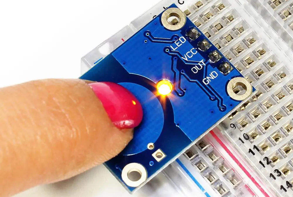
This device detects whether a finger is touching or moving over it. It converts the touch of the skin into an electrical signal and sends this to a control board (e.g., Arduino). And that board then triggers an event or action, such as turning on/off an LED or sending data to the Cloud for storage.
When you touch a sensor, a small amount of electrical energy passes through a metal strip and touches your skin. This small amount of current causes your skin to signal to your brain. It then interprets it as a tingling sensation. This tingling sensation is one of the five senses listed above and is often known as “pressure.”
We can make a touch sensor’s body from wood or plastic. Para-board sheets or plastic films can help create these bodies. We connect the sensors with wires, which go through various holes on both sides of the board.
How does a touch sensor work?
Touch Sensors consist of a sensor and an actuator.
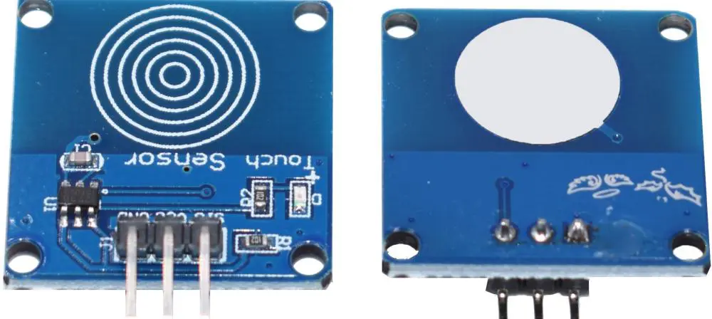
The ttp223 touch sensor is an electrically resistant material within the touch sensor that touches your skin. It converts that touch into an electrical signal. A metal film on the other side covers the resistance area, creating a touchpad. When we apply pressure to this pad, the electrical resistance indicates pressure. Next, we connect the metal film to digital pins (e.g., “2” in Arduino). Finally, we call the signal that the computer receives an analog output.
The actuator is the circuit that converts the signal into electric pulses. This can be a motor connected to a battery, which rotates when low input (e.g., “1”). The actuator can also be a light-emitting diode (LED), which turns on when there’s no input (e.g., “3”). Next, we connect the LED. Then we can use this to control devices such as an LED connected to a microcontroller. They include Arduino or PICAXE.
Using several joints and connectors makes it possible for sensors to create many different shapes. For example, we can bend a sensor with six joints into a “Z” shape. It allows you to touch different forms from both sides easily. Likewise, we can make a similar sensor into a square-shaped pad. They work with touch screen devices.
We create this sensor using a thick caulk gun to fill the joints with glue. The glue then hardens into a solid piece of plastic, and the joints are full of gold powder. We call this 3D printing. It is faster and more precise than traditional plastic manufacturing techniques.
A simpler method is to bond several joints together. It creates many sensors in different sizes and shapes.
Touch sensor applications
There are many different applications for touch sensors.
1. Touch sensor in robotics
There are many ways for touch sensors to work in robotics. For example, we make some with different joints to change into different shapes and sizes. In addition, these sensors often work as obstacle detectors. This allows the robot to avoid colliding with walls or furniture.
2. Touch sensor in home appliances
We can use touch sensors to control different devices at home. For example, you can turn on a TV or change the volume using a sensor made of plastic film and elastic bands. This sensor can easily slide on your hand and uses light pressure to change states (e.g., brightness).
3. Smartphones
Some touch sensors consist of a single strip of temperature-sensitive paper. They sell for about $2. With this sensor, you can easily touch and see the temperature in your hand.
4. Touch surfaces for electronic devices
Touch surfaces for electronic devices have become very popular. They offer many methods of controlling the device hands-free. Devices can include game consoles like Xbox 360 Kinect and mobile phones.
5. Automotive technology
Specialty touch sensors are helpful in the latest innovations. They include gesture control, proximity, and haptic feedback. With the new technology, touch sensors can access information. They also operate electronic devices and even control a vehicle.
An Arduino touch sensor is just a pressure sensor. So, when you press on a keyboard, a pressure sensor converts your touch into an electrical signal. Then, it sends it to the computer or smartphone you’re using.
6. Touch sensor faucet in kitchens
We can install touch sensors to control certain water features. For example, touch sensors are on faucets or bathroom taps to turn on or off water flow by touching a sensor.
7. Touch sensor paint
Touch sensor paint is a kind of paint that can change its color when touched with something cold or hot. You can use this paint on walls, furniture, or accent pieces in your room.
8. Industrial applications
Industrial touch sensors are essential in factories and workshops to control different machines. For example, we can place sensors on equipment to turn it on or off when working with it.
Types of touch sensor
Touch sensors are special pressure sensors that can read both air and contact pressure.
Touch sensors are simple but very effective. They don’t need special hardware or sensors. They only need a metal film on one side and a touchpad on the other side. This is an easy and cheap solution that anyone can make.
Touch sensors are very popular in electronics. Most of these sensors use a thin plate of metal as the touchpad. They also use an elastic band to connect the two sides of the sensor. We use these sensors in projects requiring only a few resources. They include toys, household appliances, and remote control devices.
There’s a wide range of applications for touch sensors. It makes it possible to use them in almost any product or system.
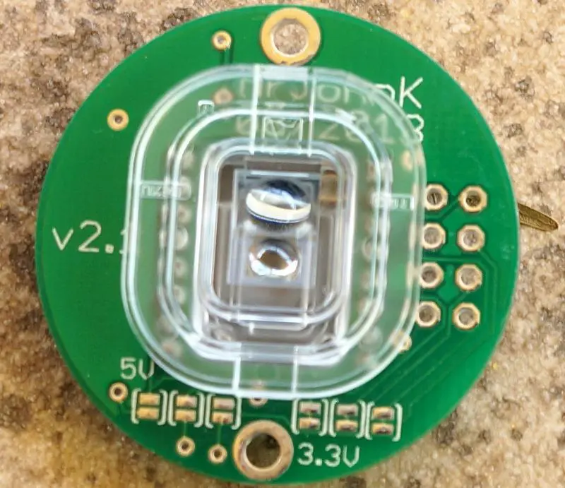
1. Capacitive touch sensor
A cap touch sensor works by detecting the change in capacitance between the two sides of the sensor when there’s pressure on one side. The pressure causes a slight change in the electrical charge between two metal electrodes on each sensor side. So capacitive touch sensor measures touch depending on the amount of change in capacitance.
How do capacitive touch sensors work
a) We use two metal plates on each side of the sensor. These two plates connect to a microcontroller with a wire.
b) When the user touches one side of the sensor, there’s a slight change in conductance between the user and the sensor. It causes a difference in the electrical field.
c) A microcontroller picks up the change in capacitance and converts it into an input signal.
d) The output gives information on touch, pressure, and touch location.
Capacitive touch sensor applications
a. We can use capacitive touch sensors in many different touch applications. For example, we use it in touchpads and buttons where a switch activates when the finger touches the pad. This touchpad allows a person to use their finger instead of a stylus to control. You can also write on an electronic device such as a smartphone or computer.
b. We can also use a capacitive touch sensor to create a multi-touch surface. More than one person can use the device simultaneously. It will recognize every touch separately.
c. We can use a capacitive touch sensor in capacitive styluses. They detect the position of a finger or stylus when touching a conductive surface.
d. We also use capacitive touch sensors in capacitive proximity sensors. They tell if a certain object is in contact or near another object or surface.
Advantages of a capacitive touch sensor
a) Capacitive touch sensors are very simple.
b) Capacitive touch sensor is a very low-cost solution. As a result, we can use them in various applications and products.
c) Capacitive touch sensors need no extra hardware or power source to function.
d) Capacitive touch sensor doesn’t need extra material to work properly. Instead, it requires two metal plates and other materials. They include the rubber band, plastic film, paper, or conductive paint.
Disadvantages of a capacitive touch sensor
a) Capacitive touch sensor doesn’t have any memory. Therefore, we cannot use them to recognize pressure.
b) Capacitive touch sensors don’t have any unique sensing ability.
c) Capacitive touch sensor needs low voltage (4V or less). This high voltage is necessary because the microcontroller consumes the most current. After all, it’s very small and power-hungry.
2. Resistive touch sensor
A resistive touch sensor is a pressure sensor. It uses conductive rubber, silicone, or metal to create a touch-sensitive surface. When there’s pressure applied on one side of the surface, a change in resistance will occur between the two sides of the surface. We can measure and use the difference in resistance to track the pressure and position of the touch.
How do resistive touch sensors work
a) We place a conductive rubber sheet or metal electrode layers on each side of the pad or sheet. The rubber or metal layer connects to a microcontroller with a wire.
b) When we apply pressure on one side of the rubber sheet, the change in resistance will occur between the two sides of the sheet or electrode.
c) A microcontroller picks up and converts the change in resistance into an input signal.
d) The output gives information on touch, pressure, and touch location.
Types of resistive touch sensor applications
a. We use resistive touch sensors in any product where there’s a need to detect pressure. It uses this information to control or notify the user. For example, we can use it in capacitive touchpads where a switch will activate when the finger is touching the pad.
b. Resistive touch sensors are helpful in digital signage and RFID tags.
c. Resistive touch sensors are also used in smartwatches when the touch screen covers parts of the body that a user would typically cover.
Disadvantages of resistive touch sensor
a) Resistive touch sensor is not able to track movement accurately. However, we can detect or measure pressure even if the user is not touching the surface. So it’s useful only in several situations requiring accurate pressure and location detection.
b) Resistive touch sensor requires high-voltage (for example, 15V or more). This high voltage is necessary because the microcontroller consumes the most current. After all, it’s very small and power-hungry.
c) Resistive touch sensor needs a constant electrical power source to function correctly. Therefore, we cannot use it with batteries like other touch sensors.
d) Resistive touch sensors can damage easily. The rubber or conductive silicone layers will start to wear out if it’s overused. This will cause a significant drop in performance.
Difference between the resistive and capacitive touch sensor
Unlike capacitive touch sensors,
1. Resistive touch sensors don’t need special materials. They also do not need specific conductivity to work correctly. This means that we can use every material as a resistive touch surface.
2. Resistive touch sensor doesn’t need a power source to function. Instead, resistive touch sensors use the user’s body as a power source.
3. We can use resistive touch sensors in any product requiring a pressure-sensitive surface.
4. We can use resistive touch sensors in smartwatches to make the screen’s cover of rubber or conductive silicone.
5. Resistive touch sensors cannot track movement accurately. However, we can detect and measure pressure even if the user is not touching the surface. So it’s useful only in several situations requiring accurate pressure and location detection.
6. Resistive touch sensor requires high voltage (for example, 15V or more). This high voltage is necessary because the microcontroller consumes the most current. After all, it’s very small and power-hungry.
7. Resistive touch sensor needs a constant electrical power source to function correctly. Therefore, we cannot use it with batteries like other touch sensors.
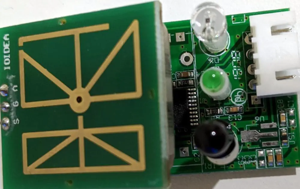
Infrared touch sensor
An infrared touch sensor is also called an IR touch sensor or an IR proximity sensor. It is a pressure-sensitive surface. It uses infrared light to detect objects’ presence, location, and movement. This sensor allows users to interact with physical objects without touching them.
IR Touch Sensor features
a) Infrared light can pass through thin layers to work in very thin objects.
b) Infrared touch sensors follow the human body’s infrared waves that follow nerves and muscles.
c) Infrared touch sensor does not need a power source to operate. Users can place their hands close to it to get desired results.
d) Human eyes do not easily detect infrared light. So, it’s helpful in controlled environments where users need to wear special glasses.
e) The infrared light from the sensor can detect objects at 30cm (11 inches).
Infrared touch sensor disadvantages
a) Infrared light is not visible to human eyes. So, it’s inconvenient to use in public places like airports and hospitals.
b) Infrared light cannot detect motion, but it can detect pressure and proximity. So it’s useful only if there’s an object with pressure-sensitive buttons. Examples include a TV remote control or gaming controller.
c) Infrared touch sensors are not able to track movement accurately.
d) Infrared sensor doesn’t detect objects with good accuracy. Users have to move their hands closer to the infrared touch sensor. Then their hands will activate the button or knob when they are in the range.
e) There are no pairs of infrared touch sensors designed to work together. So it isn’t easy to pair them together and get the desired results.
It’s impossible to use infrared touch sensors in smartwatches that need IR signals to work correctly.
Difference between the infrared and capacitive touch sensor
a) Capacitive touch sensor follows a human body’s electric waves to detect objects accurately. Unlike infrared, capacitive sensors can detect pressure, movement, and location.
b) Infrared light cannot detect electrically conductive objects. But capacitive sensors can detect conductive objects.
c) These sensors don’t require a power source to operate. But capacitive sensors require a power source to function correctly.
d) Infrared sensors don’t detect objects accurately. Instead, they follow the user’s nerves and muscles. Capacitive sensors use electric charges to detect objects with good accuracy.
e) Capacitive touch sensors cannot track movement accurately. Likewise, infrared touch sensors can’t track movement accurately.
Surface acoustic wave (SAW) touch sensor
A surface acoustic wave touch sensor, also called a SAW touch sensor or SAW proximity sensor, is a pressure-sensitive surface. It uses vibrations in sound waves to detect objects’ presence, location, and movement.
These proximity sensors are common because they require special materials. These materials include aluminum oxide or silicon nitride to work correctly. However, they are not suitable for mass production. They are hard to manufacture and expensive. Nevertheless, these proximity sensors are helpful in the aerospace industry and scientific research.
SAW Touch Sensor features
a) SAW touch sensors have high sensitivity to detect movement with good accuracy. For example, a surface acoustic wave touch sensor can detect the movement of a fly’s wing if the fly is touching the surface.
b) Different kinds of SAW touch sensors with different response times: 1ms and 50ms. Compared with the capacitive touch sensor, 50ms SAW touch sensors could detect movement and pressure better.
c) SAW touch sensors require high-voltage (for example, 15V or more). This high voltage is necessary because the microcontroller consumes the most current. After all, it’s very small and power-hungry.
d) SAW touch sensors are not able to track movement accurately.
e) SAW touch sensors could not detect objects with good accuracy. Users have to move their hands closer to the SAW touch sensor. Then their hands will activate the button or knob when they are in the range.
f) It’s impossible to use surface acoustic wave touch sensors in smartwatches that need IR signals to work correctly.
Advantages
a) SAW touch sensors are not easily damaged or destroyed. In addition, they are environmentally resistant because they consist of tough materials.
b) SAW touch sensors have a wide range of use in different environments like in aircraft, car dashboards, factory production lines, and labs.
c) SAW touch sensors could detect objects with high accuracy.
Disadvantages
a) Surface acoustic wave touch sensor is not using low-level signals. So it cannot detect small signs as accelerometer and proximity sensors do.
b) SAW touch sensors cannot detect non-conductive objects or objects with low conductivity.
c) Surface acoustic wave touch sensor requires high voltage to work correctly. Therefore, it’s not suitable for Bluetooth, NFC, and wireless devices. They require low power.
d) SAW touch sensors are not able to track movement accurately.
e) It’s impossible to use surface acoustic wave touch sensors in smartwatches that need IR signals to work correctly.
How Do Touch Sensors Work With Arduino?
Introduction
Touch sensors are devices that detect touch or contact by a finger, stylus or other object. They allow interacting with electronic systems in an intuitive, tactile way. With the Arduino platform, various types of touch sensors can be easily interfaced to create projects with touch input.
This article provides an overview of popular touch sensor technologies and how they can be wired up and programmed with Arduino to detect touch input in DIY projects.
Types of Touch Sensors
Some common types of touch sensors that can be used with Arduino are:
Resistive Touch Sensors
Consist of two thin conductive layers separated by an air gap. When pressure is applied, the layers touch conducting current that’s detected. Simple construction but prone to damage.
Capacitive Touch Sensors
Detects touch based on capacitance change of a copper pad when a finger comes close. No direct contact needed. More sensitive and durable than resistive types.
Piezoelectric Touch Sensors
Uses crystals that generate voltage when mechanically stressed. Detects touch pressure and force. Highly responsive with solid state construction.
Strain Gauge Touch Sensors
A strain gauge arrangement attached to a springy surface detects bending from touch pressure. Capable of highly sensitive force measurement.
Optical Touch Sensors
Use IR LED beams and detectors to detect touch position. Offers zero-force detection. Used in devices with glass interfaces.
Interfacing Resistive Touch Sensors
Resistive touch sensors consist of a thin metallic coating on the bottom and a flexible coating on top, separated by an air gap. When pressed, the two layers contact closing a circuit.
To wire a resistive touch sensor:
- Connect one layer to +5V
- Connect second layer to an input pin through a resistor
- Touch makes layers contact, current flows through the resistor
- Input pin reads a HIGH
- No touch gives a LOW reading
The resistor determines sensitivity. Lower values make it more sensitive to light touches. 10k to 1M ohm is common.
Here is Arduino code to detect touch input:
const int touchPin = 3; // Touch connected to pin 3 void setup() { Serial.begin(9600); // Start serial monitor pinMode(touchPin, INPUT); // Configure pin as input } void loop() { int touchState = digitalRead(touchPin); // Read touch sensor if(touchState == HIGH) { Serial.println("Touched!"); } else { Serial.println("No touch"); } delay(100); // Small delay }
When touched, “Touched!” is printed on the serial monitor. Otherwise “No touch” is displayed. The reading is taken every 100 milliseconds.
Interfacing Capacitive Touch Sensors
Capacitive touch sensing uses human body capacitance to detect touch. An Arduino capacitive sensing library makes it easy to interface sensors.
The capacitiveSensor library provides:
- capacitiveSensor() – Constructor to specify send and receive pins
- capacitiveSensorRaw() – Gives raw sensor reading
- capacitiveSensor() – Adjusted reading from 0 (no touch) to high values (touch)
A threshold on the reading differentiates between touch and no touch.
Sample code:
#include <CapacitiveSensor.h> int sensorPin = 4; // Sensor on pin 4 int threshold = 1000; // Threshold for touch detection CapacitiveSensor sensor = CapacitiveSensor(2, sensorPin); void setup() { Serial.begin(9600); } void loop() { long measurement = sensor.capacitiveSensorRaw(30); if(measurement > threshold) { Serial.println("Touched!"); } else { Serial.println("No touch"); } delay(50); }
The threshold value needs tuning for reliable touch detection. Higher values make it less sensitive.
Interfacing Piezoelectric Touch Sensors
Piezoelectric crystals generate a voltage when mechanically deformed by touch pressure.
To interface:
- Connect one terminal directly to an analog input
- Add a resistor from second terminal to ground
- Apply input smoothing with capacitor
Arduino code:
const int sensorPin = A0; // Sensor on analog pin A0 void setup() { Serial.begin(9600); } void loop() { int sensorValue = analogRead(sensorPin); if(sensorValue > threshold) { Serial.println("Touched"); } else { Serial.println("No touch"); } delay(50); }
The analog reading ranges from no touch to full pressure touch. Setting a threshold performs touch detection.
Interfacing Optical Touch Sensors
Optical sensors use LEDs and phototransistors to detect finger interruption.
To connect:
- LED connected to digital OUTPUT pin
- Phototransistor to INPUT pin
- Finger blocks LED light reaching phototransistor
- Input pin reads LOW on touch
Arduino code:
const int ledPin = 13; const int sensorPin = 7; void setup() { pinMode(ledPin, OUTPUT); pinMode(sensorPin, INPUT); digitalWrite(ledPin, HIGH); //Turn on LED } void loop() { int touchState = digitalRead(sensorPin); if(touchState == LOW) { Serial.println("TOUCH!"); } else { Serial.println("No touch"); } delay(200); }
When light is blocked by touch, “TOUCH!” is printed indicating detection.
Advanced Touch Sensing with Arduino
More advanced techniques can be implemented in code for improved touch sensing:
Noise filtering – Add averaging of readings over a time period to reduce noise.
Hysteresis – Use two different thresholds during touch detected and no touch states to avoid jitter.
Auto-calibration – Automatically determine touch threshold by sampling no-touch readings on startup.
Multi-touch – Use multiple sensors to determine touch location and number of concurrent touches.
Gesture recognition – Detect common gestures like tap, swipe, pinch etc. based on touch patterns.
Machine learning – Collect training data to build ML models that classify touch inputs.
Applications of Touch Sensing with Arduino
Arduino-based touch sensing opens up many possibilities for innovative projects and products:
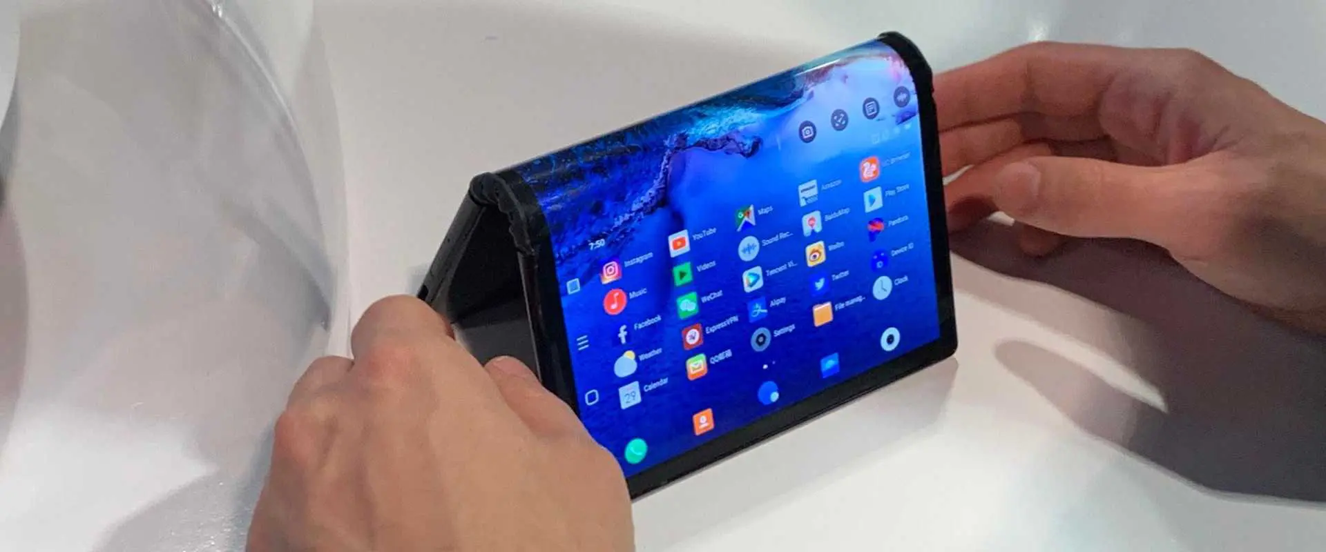
- Interactive interfaces – Touch screens, displays, tablets, panels etc.
- Smart home controls – Touch based lighting, appliance control panels.
- Wearable/Fashion tech – Interactive clothing with touch sensors.
- Musical instruments – Touch sensitive piano, guitar and other music systems.
- Toys & Educational kits – Enabling interactive play through touch.
- Industrial controls – Replace mechanical buttons with robust capacitive touch interfaces.
- Assistive technology – Enabling and simplifying input for special needs users.
Conclusion
Various touch sensing principles can provide interactive input to Arduino projects. With capacitive touch capability inbuilt into new Arduino boards, it’s easier than ever to experiment with touch interfaces. Advanced software techniques improve touch detection reliability and allow multi-touch functionality. Touch sensing opens up Arduino for creating innovative, tangible interfaces between the physical and digital world.
Frequently Asked Questions
Here are some common questions about using touch sensors with Arduino:
Q: Which touch sensor is easiest to use with Arduino?
A: Capacitive touch sensors are easiest as they require minimal components and work without physical contact. Many new Arduino boards have capacitive sensing built-in.
Q: How do you connect a resistive touch screen to Arduino?
A: Connect top layer to power, bottom layer to an input pin through a resistor. When pressed, the layers contact closing the circuit, which Arduino detects as a HIGH.
Q: Can Arduino support multi-touch sensing?
A: Yes, by using multiple touch sensors and advanced software techniques like interpolation, Arduino can detect multiple concurrent touches.
Q: What materials can be used as capacitive touch sensors?
A: Any conductive material like copper tape, aluminum foil, stainless steel can act as a capacitive sensor when connected to Arduino. Even food items like bananas work!
Q: How sensitive is an Arduino capacitive touch sensor?
A: It can detect touch through 2-3 mm of plastic or glass as human body acts as the second capacitor plate. So it is quite sensitive.