What do you need to know about PIR Sensor?

PIR Sensor Circuit

PIR sensors play vital roles in modern daily life. No one can imagine starting without them, as they are present in almost all modern devices because of their amazing features, which include consistency, easy usage, and cost-efficient.

These sensors are mainly used in security alarms. Door openings, lift lobbies, vending machines, auto light switches, and much more. Moreover, as these sensors give a variety of benefits, it also takes part in projects like Arduino and Raspberry. This article, however, tells you about PIR sensors, their usage, applications, and working principles. 

What Is PIR Sensor?

Passive Infrared or PIR sensor refers to a type of sensor that helps in measuring the light of infrared radiation coming from objects such as animals or the human body. PIR sensor has the ability to detect or identify human or animal movement in a specified range. Typically, every object that has a body temperature above zero produces heat in the form of IR radiation. Therefore, the higher the temperature of the object, the greater the radiation. Moreover, the human eye cannot see or observe these radiations because of theIR wavelength it emits. Thus, PIR sensors are basically made to detect and sense these types of infrared radiation. It usually uses in motion sensor devices, auto light switches, and security alarms.

Working Principle of PIR Sensor

PIR Sensor
PIR Sensor

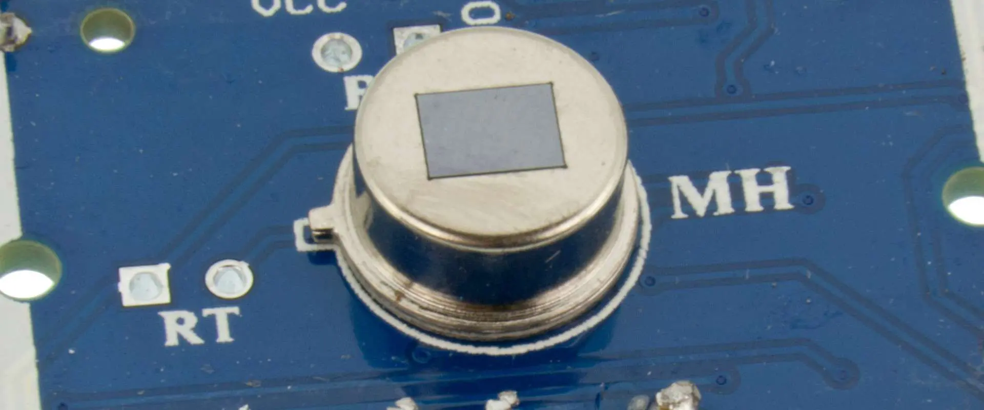
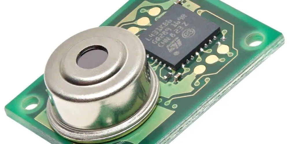
The PIR sensor contains two basic components. This includes a fresnel lens and pyroelectric sensor. The sensor comes in a circular metal form which contains a crystal in a rectangular form right in the middle of it.

However, the fresnel sense refers to a type of lens that identifies the infrared signals through a pyroelectric sensor. Moreover, a pyroelectric sensor can detect various levels of infrared radiation.

The Pyroelectric Sensor

A pyroelectric sensor contains a window with two slots in a rectangular form. Moreover, it comprises silicon coating, which allows the infrared radiation to flow simply. Then, it has two separate electrodes of the Infrared sensor. In both of these electrodes, one produces positive output while the other produces negative output. 

However, when the movement in the sensor region stops, then both rectangular slots identify similar Infrared radiation, which gives zero positive output signal. Even when the body of an animal or human moves in a sensor region, it just interrupts half of the sensor first. Thus causing a positive change between the two parts. However, when the body moves through the other half, it generates the opposite result, a negative output signal. The changes between the voltages detect the motion.

Fresnel Lens

A Fresnel lens basically enhances the field and capacity of view of sensors. It contains the capacity to gather light as well as being compact and lightweight. Hence making the size of the sensor small yet powerful.

When the body of an animal or human enters the sensor detecting range, the sensor automatically starts getting the IR wavelength of the light from the object. When it detects the infrared waves, it automatically turns on the light. However, when a body does not pass through the range, the sensor cannot sense any wave and automatically turns off the light. So a type of sensor that senses waves and switches lights is called a Passive IR sensor light. Moreover, if an object or body remains in the detecting place, the light also stays on constantly. But as the body or object leaves the detecting place, the delay automatically turns off the light.

Specification & Characteristics of PIR Sensor

PIR sensors offer various types of specifications and features. Some of them include voltage supply input and output. The input must range from +5 Volts, while the output voltage must range to 3.3 volts. It does not detect the human or object but also differentiates between them properly. Moreover, it contains both non-repeatable and repeatable operation modes. The drain of the current must stay above 60uA while the angle of detection must stay above 140 degrees. At the same time, it offers a distance of detection ranging from 7 to 3m. It contains a 2.5s blockade time default. Lower utilization of power must range 65mA while working temperature between+80 -20ยฐC. 

Different Types of PIR Sensors

Passive Infrared sensors have two types. These types include;

ยท Thermal Infrared Sensor

Pyroelectric IR sensor or Thermal IR sensor uses thermal sources such as infrared, which helps in detecting objects. These sensors process slowly and give slow detection and response time.

ยท Quantum Infrared Sensor

Quantum IR refers to a type of sensor that detects or identifies photos present over the wavelength. However, these photons respond more quickly than detecting heat. This type of sensor operates efficiently and has fast detection and response time. Though, it requires a proper and constant cooling mechanism to measure the exact location.

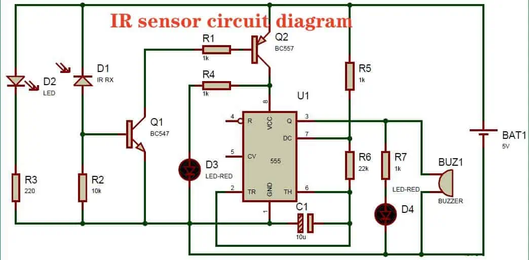
Circuit Diagram Explanation of PIR Sensor

PIR sensor proves ideal for installing in security systems. It offers features like robustness and low cost, which makes it perfect to use in the design of security circuits. The PIR sensor supports the circuit to make a motion detector device along with a relay.

This relay turns on the light as the motion detector senses any human movement. Motion detector PIR circuit requires a few basic components to make. This includes a PIR sensor, A relay of 5 V, a BC547 transistor, a 1N4007 diode, a 1k Ohm resistor, an electric bulb, and a 9 V battery.

Major Applications Of PIR Sensor

FULL PCB MANUFACTURING Quote

Passive Infrared sensors are used in a variety of applications and devices in distinct fields. These fields include a lift lobby, outdoor light automatic switching, and covered parking lots. Moreover, it also uses automatic switches for garden lights which work on the human presence. Also it is used in automatic doors of shopping malls which also works on sensing a human presence. Here are two basic yet innovative design projects of PIr sensors. 

ยท Automatic Door Opening System

The latest, innovative automatic door system uses a PIR sensor to operate. When a human goes through an automatic door, the sensor produces output pulses.

However, these pulses go to a microcontroller. This microcontroller controls and manages the motor driver. It accepts the input pulses and enables the motor driver to work appropriately.

ยท Security Alarm System

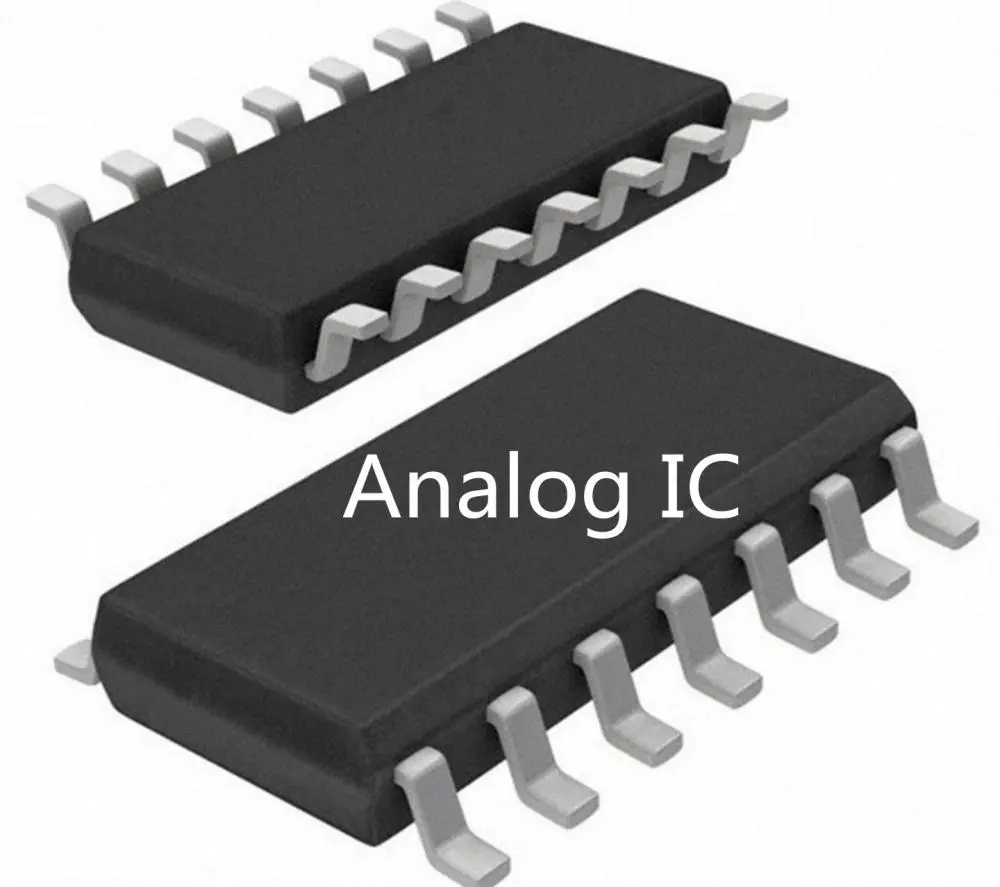
Banks and big companies that need utter safety of their assets use security systems. These systems use PIR sensors to work. The circuit contains IC UM3561. It refers to a type of integrated circuit.

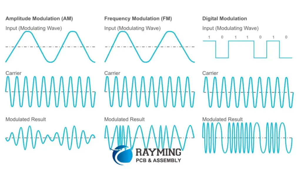
This special IC takes input in digital signals and produces multi tones for the alarm like police, ambulance, and fire brigade sirens. Like other sensors, it detects the presence of humans as one passes through it, and it gives output in digital form. This output goes to the IC UM3561, which produces the desired siren.

The Ultimate Guide to Signal Conditioning Circuit

signal conditioning circuit

The process in which we collect the data with the help of a signal conditioner is known as signal conditioning. This device will convert the input mechanical signal into another form known as an output signal.

We do this so that we will convert difficult data into easy data which a user can read easily.

We use this device because it is more convenient than human working as it is more accurate in calculations.

It converts hard reading of data into simplest ones. Not only this but this signal conditioner also does many other useful functions which are not easy for humans to do in less time. We humans are more efficient than machines, but still, we made some mistakes that make us less efficient than machines in some aspects.

Now we will discuss the structure of the signal conditioner :

The signal conditioner will convert the input mechanical signal into another form known as an output signal. We do this so that we will convert difficult data into easy data which a user can read easily. In all of its functioning, signals plays an important role as it converts from mechanical to other type of signals, which are readable and easy to monitor.

The signal conditioner has different types, which depend on the physical value as well as on specific features.

Types of Signal Conditioning Circuit 

Signal conditioning PCBA

ยท Temperature Signal Conditioning Circuit 

There is some kind of conditioners that are responsible for measuring temperature of different ranges; they are known as temperature conditioner. They are used in the fields where we have to deal with sensors and deals with other aspects. After examining these, we will transfer signals ahead for further examination.

ยท Thermocouples

Thermocouples are another type of conditioner, as they are most common in industries in building applications. The output of the thermocouples is nearly to +ve or -ve 80 million volts. This is such a small amount of voltage which is difficult to monitor and display as they are weak. Signals with more temperature are easy to manage and display.

Signal conditioning is important not only for making signals stronger but also for fixing temperature measurement mistakes caused by something called “cold junctions.” You see, when we connect a thermometer thingy called a thermocouple to a measuring device, there’s a voltage that shows up at these junctions, and they’re cold, hence the name. These cold connections mess up the real temperature readings and give us wrong results. But fear not! Temperature signal conditioners come to the rescue. They fix these variations and make sure we get accurate temperatures. They’re like the superheroes of thermometry, saving us from bad measurements and keeping things cool. Now that’s what I call a hot topic!

ยท Thermistors Signal Conditioning Circuit 

So, there’s this thing called a thermistor, and it’s a fancy temperature sensor used in all sorts of industrial stuff. But here’s the deal: this sensor needs some special treatment to work properly that requires current and voltage. The way we give it this attention affects how stable and accurately it works.

Now, temperature signal conditioners step in as the cool cats take care of thermistors. They not only give them a boost but also help them chill out (low pass filtering), making them super easy for digital devices to understand. 

These signal conditioners are like the backstage crew for thermistors, making sure they shine bright on the temperature measurement stage. They’re the heroes that make sure things go smoothly. So next time you see a thermistor, say, “Thanks for being cool, little temperature detective!”

Functions of a Signal Conditioning Circuit 

FULL PCB MANUFACTURING Quote

ยท Signal Conversion

The signal conditioner will convert the input mechanical signal into another form known as an output signal. We do this so that we will convert difficult data into easy data which a user can read easily.

In all of its functioning, signals plays an important role as it converts from mechanical to other type of signals, which are readable and easy to monitor. It can convert any kind of signal into another form of it as we discuss it earliest.

ยท Linearization

This is a process in which a conditioner performs a function where the sensors will not catch a straight line with the help of a physical medium.

In it, it will catch signals from the software and convert them into another form of signal. Letโ€™s be honest. We all want a correct and accurate result, and by using this process known as linearization, we can get desired output.

ยท Amplifying

After linearization, we have another step amplifying, as it is a multi-stepped process. It will work under two major points

  1. We will increase the frequency of the signals which we are taking as an input.
  2. The option is that we can increase the ratio of signal to noise.

There are other types of signals known as Dc input signals, and for many other purposes, conditioner uses amplifiers of different ranges.

ยท Filtering

Listen up, folks! Signal conditioners have this function called filtering, and it’s all about cleaning up the signal’s frequency party. We want to keep the good stuff and kick out the noisy stuff. As we all know, it is the most important part of filtering.

  1. Now, there are different types of filters, and they can be built with weird components. Passive filters are like a small thing, using stuff like capacitors, resistors, and inductors. They keep the gain (volume) at a max of one, so no one gets too loud.
  2. On the other hand, active filters are like the life of the party! They mix passive components with active ones, like operational amplifiers and transistors. 

Remember, filtering is the way to keep the signal accurate and noise-free. As it is the most important part of the filtration.

Evaluation and Smart-functions

To get more benefits from it, we modify the signal conditioner into a modern conditioner having more advanced features in it. This can include weird alarms and different sounds. We modify this so that we will get advanced features.

ยท Interfaces

Ok, so, like, signal converters help send signals to machines. They can do it in two ways – analog or digital. Analog signals are like +/- ten V or +/- twenty mA, which is pretty simple to handle, but each one needs its wire. And they can even transmit extra info, like when your sensors are feeling sad or sick or whatever. It’s like a doctor for machines. But overall the wires play an important role in it. The different information on different parts of the machines is very important as it helps in the maintenance of the machine.

A Closer Look at FCBGA: Flip Chip Ball Grid Array

Flip Chip

You might be doing the flip-chip method all wrong this whole time! The purpose of a flip chip is to reduce the connections between the chips themselves. One thing that eases the purpose of the flip chip is the solder joints. 

You only need to put these solder bumps on the upper surface of the pads. The first step of the process is to use and place circuits on the semiconductors. After that, you need to position the pads and place the solder carefully on individual pads. 

Now it’s time to cut the chips and flip them all. It will assist you in placing the solder on the pads as well. In the end, you need a reflow method for the solder that solidifies its bonds with all the pads.

We know that all this must be too overwhelming for you to read straight in the introduction. No worries, since this post is going to render you all the necessary information about the flip-chip method in a fun and insightful way. 

Letโ€™s get started with this fun ride without wasting any instants!

Common Flip Chip Ball Grid Array Packages

Wait, did you not know about common flip packages? Well, these are important to have a look at in order to understand this whole process. These are made from ceramic substrates, and you can use natural laminate for these as well.

 The flip-chip wafers give you an edge since you can use two metallic layers to group them or assemble them in as many layers as you want. 

Why Use a Flip Chip Ball Grid Array?

Now that we are discussing the flip chip in detail. Have you ever wondered why they even matter in the first place? Sit back and relax since this section is going to shed some light on the major benefits of using a flip chip BGA for you:

These are reliable for intense machinery and high-frequency tools.

Flip chip BGA is always small and takes less space on the wafer, which makes it dependable for regulating inductance and increasing the transmission of signals.

The flip chip prevents moisture from taking over your wafer as well.

It allows more thermal conductivity to take place. 

The flip chip process is more practical to use instead of the regular wire bonding technique.

The flip-chip BGA method is a cost-effective technique that all producers can perform.

The flip chip is highly inevitable for the fine performance of common semiconductors used today.

Drawbacks of the Flip Chip Ball Grid Array

It’s time that we leave no stone unturned in providing you with an unbiased review on flip-chip BGA. Hereโ€™s the thing, the flip chip does have several benefits to offer. But you cannot use this method blindly. There have been cases when the recklessness of the producers in using flip chips caused them irreversible trouble. So the common drawbacks of the flip chip method that you need to know are:

They are carrier-less which means you cannot always replace them easily when needed

Due to no carrier, these are not suitable if you are trying to install them on your own (manually)

You need highly flat surfaces to combine flip chips for efficient performance 

The flat surface needs to be maintained for temperature regulation which is not always easy to achieve 

Factors affecting the Flip Chip Ball Grid Array methods: 

Now you know about the common disadvantages of flip chips. There are some factors that you need to take care of while working with flip chips. These are:

Keep the surface as flat as possible

Maintain optimum temperature on the flat surface

Control thermal expansion as it can develop cracks in wafer

Use suitable flip chips right from the start because they don’t allow easy replacement

Market Overview of Flip Chip Ball Grid Array

The connections that develop among flip chips are collapse connections. It is a process that joins the semiconductors and integrated components to the circuits that are on the outer side. All this happens with the help of industrial-grade solder bumps that you need to accurately place on the pads. If you ask for one thing that acts as a fundamental block to make it all function is the solder bumps.

Without these, no wafer can get the benefits of flip chips at all. You need to integrate the circuit on the wafers before proceeding with the process. One chip contains a pad and a solder ball of its own. After cutting the chips, it’s time that you face them toward the external circuit. All that remains is to reflow the solder to harden the bond between the solder and the setup.

Market Dynamics

FULL PCB MANUFACTURING Quote

High-performance Flip Chip Ball Grid Array

The semiconductors need to offer precise electrical performance, or else they will not meet your expectations at all. As you know, BGA always has small connections among its components. It means it reduces the resistance of these connections at the same time. Due to this, it boosts the electrical performance. Now, if you are successful in increasing the electrical performance, it will automatically improve the signal transmission and signal speed. 

Miniaturization

FCBGA impresses producers due to its irresistible benefits. It is now more important than ever for producing small and midrange consumer electronics. Wearables and mobile phones cannot work in a natural state without this method. Not only this, but CPUs also start performing better due to the excellent miniaturization offered by FCBGA. 

Improved signal integrity

You will find this interesting. FCBGA maintains the connections of IC and PCBs that give birth to short signal routes. If a signal route is short, it will prevent the disturbances as well. Signal disturbance mostly happens when there is too much noise at the backend. The solder amount used by this technique is less, which is beneficial for preventing signal fluctuations. 

Market Restraints of Flip Chip Ball Grid Array

Expensive Packaging

You might be hurt to know this, but FCBGA is not affordable at all. Only giants of the industry can think about using this method for efficiency. Several steps of this process require an individual budget that definitely is important to consider in case you need to save your business from bankruptcy. 

High Cost

The FCBGA sector is already facing enough problems since analyzing and manufacturing wafers through this method is expensive. It is a high-cost deal that hampers other processes as well. There are some other technologies, like metallization and lithography, that increase the cost of FCBGA. 

Competition

The FCBGA sector has now become ever-competitive. There is an extreme sense of remaining ahead of each other among business rivals. It is healthy, but just to some extent. Such a throat-cutting competition can create a negative impact on the buddy companies that are just stepping into this field. 

Market Opportunity for Flip Chip Ball Grid Array

Enhancing Performance

You can rely on FCBGA since it produces highly efficient semiconductors. The role of these chips is to make sure that the devices perform the best possible in the long run for the users. Due to this reason, these are useful for extreme and intense applications like super-computing operations, complex data processing, gaming, and much more

Personalization

Customization is another factor that gives FCBGA an edge over the others. It is because this produces mostly small and portable devices that are easy to change and personalize. 

Factors driving the development of the Flip Chip Ball Grid Array market

 The growing attraction of miniaturization is one of the primary factors that is contributing to the expansion of the FCBGA sector. Not only this, IoT and its vast applications in the lives of consumers are also drawing the attention of investors in the market. 

Key trends in the Flip Chip Ball Grid Array market

 Some enticing trends that are important for setting a direction for the FCBGA domain are:

The growing need for HDI that promises more miniaturization

Significance of industrial-grade materials

Solutions for thermal regulation

Applications of FCBGA in the field of 5G infrastructure

XC6SLX16-2FTG256I FPGA vs. Traditional Microcontrollers: Which One is Right for Your Project?

Xilinx Artix 7

Technology and electronics are constantly evolving. As a result, you have access to a wide range of innovative applications. A few years back, it was a microcontroller that revolutionized the world, but nowadays, FPGS is making the buzz. Both are useful in electronic projects. Field-programmable gate arrays and microcontrollers are both different. If you need clarification on using an XC6SLX16-2FTG256I FPGA or traditional microcontrollers for your project, then you don’t need to worry. The following content will help you decide which one is better.

Our vote is in favor of FPGA XC6SLX16-2FTG256I, but we will let you decide. The following content will help you understand the differences between these too. It will also help you to make an informed decision about which one is perfect for your project. That’s why it is necessary to know the basic difference between these two.

 What Are Microcontrollers and FPGAs?

 Before we dive into the differences between microcontrollers and XC6SLX16-2FTG256I FPGA FPGAs, let’s first define what they are.

 What Are Microcontrollers?

ย A microcontroller is a small computer on a single IC. It can control various devices in electronic projects. They are pre-programmed with specific instructions. They can perform several useful tasks, such as reading sensors and controlling motors. It can send data to other devices, but its compatibility is an issue sometimes.

What Is XC6SLX16-2FTG256I FPGA?

 XC6SLX16-2FTG256I FPGA FPGAs, on the other hand, are programmable logic devices. That allows users to design their own digital circuits. These are not pre-programmed, but rather you can program and reprogram them. If you particularly talk about the XC6SLX16-2FTG256I. It is manufactured by Xilinx. It belongs to the Spartan-6 family of FPGAs. This FPGA has 16,640 logic cells for better function. It has an amazing 576 KB of RAM and 20 DSP slices. It operates at a maximum speed of 400MHz. The FPGA is also so amazing because it has a range of I/O interfaces and Ethernet. That’s why it is suitable for a variety of applications, such as high-speed communication and image and video processing. This FPGA is also suitable for digital signal processing. As a result, you can achieve your electronic objectives so easily.

Differences Between Microcontrollers And XC6SLX16-2FTG256I FPGA

 Now you have a basic understanding of what microcontrollers and FPGAs are.  Letโ€™s dive into depth to know the differences between the two.

1. Flexibility For Programming

One of the key differences between the microcontroller and XC6SLX16-2FTG256I FPGA FPGs is their flexibility. Microcontrollers are not flexible in terms of programming. It is pre-programmed with specific instructions. That’s why they can only perform tasks that they have been programmed to do. On the other hand, FPGAs are able to perform a wide range of tasks, making them much more flexible than microcontrollers. Reprogramming is easy for XC6SLX16-2FTG256I FPGA FPGs, as compared to the microcontroller.

2. Processing Speed Matters

 Another important difference between microcontrollers and XC6SLX16-2FTG256I FPGA FPGs is their processing speed. Microcontrollers have a downside in matters of processing speed. They take time to take instructions and process them. In short, all microcontrollers typically have a lower processing power than FPGAs. It means that they may struggle to perform more complex tasks. XC6SLX16-2FTG256I FPGA FPGs have a higher processing power with an amazing 576 KB of RAM and 20 DSP slices. That’s why it can handle more complex tasks with ease. So again, FPGA wins the race.

3. Development Time And Customization

ย The development time is again different for both microcontrollers and FPGAs. Microcontrollers are pre-programmed. That’s why they require less development time. XC6SLX16-2FTG256I FPGA FPGAs require more development time. Users program it according to their needs. Again there is another thing: customization. You cannot customize the microcontroller. They are programmed with specified instructions and programs. That’s why they perform specific tasks.

However, XC6SLX16-2FTG256I FPGA offers greater flexibility than microcontrollers. That’s why you can easily customize them. Many designers compromise developmental time due to customization. Customization allows you to make you. The XC6SLX16-2FTG256I FPGA is more unique and suitable.

4. Power Consumption and Management

Designers and engineers always try hard to maximize efficiency and want to consume less power. Power consumption is another discriminating factor. It will help you decide your cup of tea.

 Some microcontrollers typically consume lower power while some consume more. It depends upon their programming and the specific task they can perform. On the other hand, every FPGA consumes less power especially. XC6SLX16-2FTG256I FPGA. So you can compare the power consumption of both for a particular project. As a result, you can choose which suits your needs. It is also possible thatXC6SLX16-2FTG256I FPGA is consuming more power when you compare it with your selected microcontroller. So power consumption is another important decision factor.

5. Price Difference

ย Price is also an important factor to consider but not that much. ย In my opinion consider the cost as the last deciding factor. If you are a hobbyist, then you must consider it. Microcontrollers are generally less expensive than. XC6SLX16-2FTG256I FPGA. That’s why if you are working on a tight budget, then go for the microcontroller. FPGAs are at a higher cost. But they can integrate into systems seamlessly. However, it’s important to note that the cost of FPGAs has been decreasing in recent years/on the other hand; its popularity is also increasing. Most designers consider it a more viable option for some projects.

Wrapping Up Things

I hope now you have a better understanding of both microcontroller and your technical requirements also matter a lot. Nowadays, devices and machines are more sophisticated, so an FPGA can fulfill your needs best. However, sometimes microcontrollers are the economical solution. That’s why it is up to you which option you go.

But nowadays, most modern applications use the XC6SLX16-2FTG256I FPGA due to its unique features. That’s why an FPGA is more sophisticated than any microcontroller. So go for any one of them by keeping your needs in mind. Above all, if you find yourself confused, you can seek professional or expert help.

How to Indicate Placement Orientation of LED on Your Boards

Led Orientation

A proper placement, labeling and orientation of components on a Printed Circuit Board (PCB) helps in reducing some of the common problems. When these things are in place, one can be sure that the components wouldnโ€™t be exposed to short-circuiting or a plethora of other electrical issues.

The two most common components to watch out for are the anode and cathode. Due to the technicalities involved in the placement, you may be unsure of how one of them should be positioned.

In this article, we compare anode vs cathode LED and help you understand the right positioning to use for any of them.

YouTube video

Understanding the Concept of โ€œLEDโ€

Light Emitting Diode, also called LED, refers to the light bulbs comprising of a wide range of tiny diodes. The work or function of these diodes is to emit light when electrical current passes through them.

When compared to the traditional or standard diodes, the LED is known for one feature โ€“ the one-way direction. Ideally, the direction or pathway for the electrical current is channeled to one direction.

LED Polarity and the Debate on Anode vs. Cathode Diode

Placement Orientation of LED

The two (2) major types of diodes you will find in a LED are anode and cathode. For what it is worth, you want to know the differences between the two. However, it is important to understand the basic โ€“ the polarity of the Light Emitting Diode.

LED polarity refers to the direction or pathway through which the electrical current is meant to flow in the diode. Since LEDsโ€™ electrical current are designed to flow in one direction; it is therefore expedient to understand the right way to channel it.

It is on this basis that we introduce you to the two primary diodes โ€“ anode and cathode. You will learn about the different functions they perform in a LED.

What is an Anode?

It is a type of Light Emitting Diode (LED) that denotes the positive side of the diode. In this case, it is the terminal in the diode, through which the electrical current is meant to pass into or enter the diode.

What is a Cathode?

It has an opposite function to what the anode does. The function of the cathode in a LED is to provide the medium for the electrical current to leave the diode.

Despite the differences in how they process or facilitate electric current movement, the anode and cathode are two terminals you need in a LED.

How to Tell Anode vs. Cathode

The easiest way to differentiate between the two is to look out for the signs or polarity markings. While the anode has the positive sign (+), the cathode has the negative sign (-).

That is the surface differentiation metric. In the next paragraphs, we will let you into some of the features that will help you differentiate between a common anode vs. common cathode LED.

The Differentiations Based on the Electrical Charge

Since both the anode and cathode deal with processing electrical current; we can use that as a way to differentiate them.

For the anode diode, it attracts a negative electric charge. This is usually a positively-charged electrode and helps the anode to act as an electron receptor. In this instance, it facilitates the occurrence of oxidation, which, in turn, attracts the negative charge.

On the other hand, the cathode attracts cation, which is the same as a positive charge. Despite the attraction of a positive electric charge, the cathode is also susceptible to the negative charging of the electrode.

To this end, it is expedient for the cathode to facilitate the following:

  • It facilitates the generation or production of electrons that create a charge.
  • The negative charge, when created, is used to facilitate the movement of the current from cathode to anode.

Techniques for Identifying Anode and Cathode in a LED

FULL PCB MANUFACTURING Quote

If you are intent on determining which of the diodes is anode and cathode, here are some of the steps or procedures to doing so:

1. Check the Diodeโ€™s Length

By merely looking at the diodes, you can tell which is which. The length is a giveaway for doing this.

Ideally, the diode with a shorter pin is the cathode and the one with a longer pin is the anode. Note that the best way to discover this is by looking at the length of the pin at the end of the diode.

2. Check the Notch

You can also use the notch to determine which of the diodes is a cathode and anode. For this exercise, look at the small, flat notch on the side of the Light Emitting Diode.

The lead or pin that is closer to the notch is the cathode while the one that is a bit far away is the anode.

3. Use a Multimeter for the Test

It is possible for you to use a multimeter for the testing or finding out of the anode and cathode. It is better to use this as a last resort, especially if you are uncertain of the outcome of the previous exercises.

Here is a walkthrough on how to get it done:

  • Diode Setting Activation:ย the first step is to turn on the multimeter to its diode setting. This helps you make a foolproof testing.
  • Probe Usage: once the setting is on, you can then use the multimeterโ€™s probes on each of the LEDโ€™s pins.
  • Diode Lighting: essentially, what you are looking for is the diode lighting up on the pins. The pin that on getting touched with the probe lights up the diode, shows that you have matched the positive probe with the anode and the negative probe with the cathode.

Note: it is possible not to get the desired results immediately when using the multimeter for the test. If that is the case, consider switching the diodeโ€™s terminals and retry the test.

4. Check the Schematic Symbol

The schematic symbol could also be of help in telling which of the terminals is a cathode and an anode. Ideally, this is possible due to the small line drawn near the cathodeโ€™s pin, and which makes a direct correlation with the small, vertical line in the diode circuitโ€™s symbol.

Although it could sometimes be faint, it is one of the best ways to determine the cathode and anode terminals in the diode.

Anode vs. Cathode Diodes: The Major Differences

Besides the length of the pins and the markings, here are a couple of additional differentiators between these two diodes:

1. Type of Terminal

The anode acts as the positive terminal, while the cathode as the negative terminal.

2. Type of Charge

The anode acts as the donor of electron, while the cathode plays the role of electron acceptor/receptor, in the sense that it assists in the generation of the charge that moves the current from cathode to anode.

3. Electric Current Flow

The anode terminal is the direction from where electrical current moves into the LED, while the cathode is the direction for the current to leave the diode.

4. Positivity and Negativity

Due to the types of charge that they generate and the current flow; anode and cathode are denoted by the type of current they process.

On the one hand, we have the anode serving as the positive terminal and the cathode serving as the negative terminal of the LED.

5. Oxidation vs. Reduction

Anode facilitates the oxidation that leads to the creation of a negative charge. On the other hand, reduction occurs in the cathode.

6. The Pinโ€™s Length

The length of the pins can also help you find out which of the terminals is a cathode and which is the anode.

Sometimes, it could be difficult to determine this due to the fact that the pins may have been subjected to manual cutting. In that case, they tend to have a similar length.

However, you can easily find out the cathode by close examination of the outer casingโ€™s edge. Here is how to go about it:

  • Find out if one side of the outer casing is flat and lined up with the diode.
  • Find out if the other side of the casing extends slightly.
  • If those parameters are met, there is a chance that the cathode is the pin nearest to the flat edge.

What Color is the Cathode and Anode?

Color could be an important consideration when looking to differentiate between cathode and anode terminals in a diode.

The simplest rule is to check the signs or markings. Usually, the positive side of the diode, the anode, is marked with the red color, while the negative is marked with a black color.

Tackling Ambiguity and Inconsistency in LED Placement and Orientation

There is a chance that the standards set out for the placement and or orientation of the Light Emitting Diodes (LEDs) are not followed.

Some of the standards are:

  • Using the positive sign (+) to mark or denote the anode and the negative sign (-) for the cathode.
  • There should be an arrow or marking moving from the diodeโ€™s pin to the vertical line in the diodeโ€™s circuit symbol.

However, the tendencies of ambiguity and inconsistency is common due to the following reasons:

Interchanged Diode Markings

The standard is to use the letter โ€œAโ€ to denote an anode in a diode and the letter โ€œKโ€ to denote the cathode.

However, depending on the manufacturer, this standard is not always followed. For example, some manufacturers could use a different alphabet.

Nevertheless, one of the benefits of using the alphabet โ€œKโ€ for the cathode instead of the letter โ€œCโ€ is to prevent the mistakes of taking it to be a capacitor.

Discarding of the Markings

As mentioned in the previous paragraphs, it is possible to use the positive sign (+) and the negative sign (-) to denote the anode and cathode terminals for the diodes.

However, there is a tendency for ambiguity, which often leads to the discarding of these markings. In their place and depending on the manufacturersโ€™ preferences, a dot and a bent outline could be used to denote the anode and cathode terminals.

THT vs. SMT Anode and Cathode Orientations

The LEDs assembled via the Through Hole Technology (THT) and the Surface Mount Technology (SMT) have distinct orientations.

The placement options for the THT include:

  • Marking of the Through Hole Device (THD) with a line at the cathode.
  • The usage of a longer pin or a flat edge for the Light Emitting Diodes (LEDs).

The Surface Mount Technology (SMT) process spells out the marking of the end of the cathode in the LED device. However, some manufacturers do not follow this and the ones that do, are not consistent with the implementation.

LED Component Orientation Benefits

Why should we place the Light Emitting Diodes, such as cathodes and anodes appropriately on the device?

Here are some of the reasons as to why you should do that:

  • It enables the proper alignment or positioning of the components in the right direction on the board or device. This way, it makes the soldering of the pins simpler.
  • An excellent LED polarity aids the connection of the diode to the right voltage source. This is an important consideration for making the supply of electric current possible.

LED & Resistor: When Do You Need the Latter?

Light Emitting Diodes (LEDs) require a specific voltage. However, if this voltage is exceeded, there is a chance that it will negatively impact the deviceโ€™s performance. To this end, you would need to use a resistor to help put things back in good shape.

Here is how to maximize the use of the resistor:

  • Place the resistor between one of the diodeโ€™s leads or pins and the connection to either the Ground (GND) or the supply voltage.
  • The right amount of resistance should be used, as it helps to regulate the Light Emitting Diode (LED)โ€™s capability to function optimally, and without burning itself out.

Final Words

Using a Light Emitting Diode (LED) helps in streamlining the flow of electricity, extending the lifespan of devices and conserving energy.

Using the tips in this article, you should now be able to place and orient the anode and cathode diodes appropriately in a LED device.

Why Do Hearing Aids Device Use a PCB?

Hearing Aids Device

Printed Circuit Boards (PCBs) are used in the medical industry because of the flexible wiring prospects they offer. Today, you can use these boards in hearing aids devices. The reasons for this are discussed in this article.

What are Hearing Aids Devices?

These are dedicated devices for boosting the audio signal reception for people with difficulty in hearing. These high-tech devices are capable of improving the audio signal transmission, as well as improving the listenersโ€™ speech understanding.

Challenges Addressed by PCBโ€™s Usage in Medical Electronics

It is noteworthy to mention that Printed Circuit Boards (PCBs) are now popularly used in the global medical industry because of the innovations they bring.

From the miniaturization capabilities to reducing costs; these boards can provide a wide range of improvements for medical devices.

Some of the persistent challenges that are addressed are thus:

Reliability

Considering that most medical devices and wearables (such as hearing aids) are exposed to dangerous environments โ€“ they need to be reliable.

PCBs have proven to be a reliable technological improvement that allow for the devices to function optimally. Ideally, your hearing aids device made with a PCB should be able to withstand exposure to extreme temperature and shocks.

Classes and Compliances

Due to the disparities of medical electronics, there is a need to choose PCBs based on their classes. For example, the Class 3 medical devices require more precision. As such, it is expected that the circuit boards must meet the following conditions:

  • Process qualification standards
  • Installation qualification standards and;
  • Operation qualification standards

Miniature Construction

The best hearing aids device uses a PCB that doesnโ€™t taken up much space. This is why the flexible circuit boards are a popular choice.

Generally, the choice of a PCB for medical electronics/devices should be based on the minimal size. This allows for the boardโ€™s fitting into the compact spacing on the device.

Flexible PCBs: The Best Circuit Boards for Hearing Aids Devices?

Hearing Aids Device PCB

The flexibility of this type of PCB makes it a popular choice not just for hearing aids devices, but for most medical devices.

Flexible PCBs, as the name suggests, are flexible circuit boards. The flexible modifications support the wrapping folding or bending of the medical devices.

Besides, when these boards are used in the hearing aids devices, they help to coordinate the entire wirings in a compact footprint.

Circuit Diagram of Hearing Aids Device

Wondering what is inside a hearing aids device? Beyond the hook that fits behind the ear, the device also has a microphone and a couple of other components.

Here is a breakdown of the different, important parts usually found inside the device:

1. The Microphone

This is one of the most important parts, as it deals with the picking up of sounds from the environment. This would then be converted to an electrical signal for further analysis and adjustments, based on the listenerโ€™s degree of hearing loss. The digital code or electrical signal can further be optimized based on the immediate environment where the listener is.

2. The Flex PCB

You can also find the flexible Printed Circuit Board (PCB) inside the device. Among many other functions, the board helps to coordinate most of the other components and wires inside the hearing aid.

It also comprises a mixture of Integrated Circuits (ICs) and a wide range of other components.

3. The Battery

The hearing aids device needs to have a source of power and that is what the battery is used for.

4. The Receiver

The receiver is a component that sees to the conversion of the amplified electrical signal into the corresponding sound. This sound would then be delivered into the listenerโ€™s ear.

5. The Antenna

The radio uses the antenna for radio frequency signal reception and transmission. We can help you optimize the antenna to fit into the hearing aidโ€™s shape and possibly tune it up to 2.4 GHz.

Why Flexible PCBs are Popular in Hearing Aids Devices

Flexible circuit boards are a popular choice for manufacturing hearing aids device because of the following reasons:

1. Miniaturization

Due to the need to reduce the size of most medical devices; it is expedient to use components that make that possible.

With flexibility and the ability to fit into smaller footprints; flexible PCBs make this possible. Thus, you can bend or wrap the boards in whatever direction and they will still perform the desired function in the device.

2. Used in Place of Wiring

These boards are commonly used in place of plug connections and wiring. This is an improvement geared towards the reduction of excessive wires in the hearing aids device.

Besides, the replacement of wires and plugs allow the flex PCBs to provide a combination of utmost reliability and flexible designs.

3. Flexible Installation Options

Have you ever manufactured a device and realized that one feature or more is missing? At times, it could be a herculean task to get those things fixed.

However, you could do better with the flexible installation options that come with flexible circuit boards.

Coupled with the high miniaturization level; it is possible to integrate new components and functions, without necessarily increasing the deviceโ€™s size.

4. HDI Capabilities

FULL PCB MANUFACTURING Quote

The High-Density Interconnect (HDI) capabilities also make the flexible PCBs a better choice for medical wearables.

The following are some of the things you need to know about the HDI capabilities:

  • Multiple Interconnects: the HDI flex circuit boards allow for multiple interconnections to be made. The interesting thing is that all these interconnections can be made without expanding the deviceโ€™s current space.
  • Versatility in Routing: the routing paths are versatile, thus, offering different ways to make the interconnections.
  • Affordability: in addition to interconnecting multiple components, the HDI flex PCBs are also affordable. When comparing a 6-layer HDI flex PCB to an 8-layer rigid PCB; the former costs less.
  • Reduce Space Requirements: HDI flexible PCBs support several interconnections even within a compact footprint. However, the space requirements are further reduced because of the presence or integration of micro, buried and blind vias.
  • Signal Integrity: the reliability and integrity of the signal is further improved due to the proximity of the components.

5. Improved Reliability

You can rely on hearing aids devices made with flexible PCBs to be highly-reliable. The reliability of the hearing aid circuit board is because of the following reasons:

  • Resistance: most flexible circuit boards are made of polyimide materials, which make the boards resistant to chemical changes, and extreme temperature exposures.
  • Minimized Connection Points: as the connection points and routing paths are knit; it is almost impossible for the hearing aids device to suffer from poor solder joints.
  • Electrical-Reliability: the electrical-reliability of the flexible PCBs also makes it ideal for use with hearing aids devices. Features like the uniform spacings and trace widths, improved dielectric constant and uniform material thickness make this possible.

6. Bending Ability

The flexibility of these circuit boards is another boost to the hearing aids devicesโ€™ function. Since flexibility is becoming a requirement for most medical devices and wearables; it makes sense to use a flexible PCB for the purpose.

Here are some of the advantages to the boardโ€™s flexibility:

  • It helps to contain the contraction and expansion of medical devices like hearing aids devices, especially during the operations.
  • The bending, folding and twisting allow for the creation of connections that could have hitherto, not been possible with the rigid Printed Circuit Boards (PCBs).

Flex and Rigid PCBs for Hearing Aids Device: Which is Better?

Both the flexible and the rigid circuit boards can be used to optimize the performance of medical devices and wearables.

However, when it comes to the hearing aids device, the flex PCBs are a popular choice. Here is how it compares to the rigid circuit boards:

Multi-Shape Formation

Flexible circuit boards can be formed into complex shapes, especially in Three Dimensions (3D). This also comes with the creation of branches to multiple connectors.

Flexibility Options

The fact that most medical devices, especially hearing aids devices have limited spaces make the flex PCBs ideal for them. The flexible folding and twisting make the board easy to fit into any of the available spaces on the target devices.

However, the integration of flexible and rigid-flexible circuit boards could also boost the hearing aids device performance. Here are some of the advantages:

Combined Functions

The rigid-flex PCBs combine the flexibility of the flex circuit boards with the durability of the rigid circuits. This is why most hearing aids devices made with this combined PCB architecture can be both flexible and durable.

Design Versatility

One advantage of the flexible PCBs is the smaller size, which also translates to less weight. However, the rigid PCBs can weigh more.

The combination of the rigid and flexible circuit boards in one footprint allows for the durability to be profound, without the size and weight of the rigid PCBs being noticed.

Conclusion

Using flexible circuit boards in a hearing aids device is a sure way to sound reception and decoding easier for people with difficulty with hearing. If you want to add more flexibility, consider going for the rigid-flex PCBs that add more durability, without integrating much of the rigid PCBsโ€™ weight and size.

What are the Design Considerations of PCB Sensors?

motion sensor

There is an endless list for the different types of sensors. These include IoT devices, environmental sensors, mobile devices, and industrial equipment. In addition, this sensor market continues to grow in order to satisfy their continuous increase in demand. As of today, where almost everything we do is linked to our individual mobile devices, we usually expect something which is new products coming with some level of connectivity. Also, we expect it to interact with its environment and the users by making use of sensors.

Asides from consumer PCB, many applications that demand the use of sensors are available. In addition, new developments in manufacturing, and other industries are beginning to cause our everyday tasks to be highly data-dependent. This is the main reason why sensor networks have not become very important.

For the purpose of this article, let us learn about what PCB sensors are.

How to Choose a PCB Sensor

Selecting sensors that need to be utilized in newly created products entails more compared to just thinking about that phenomenon you wish to measure. In addition, you need to consider the environment that youโ€™ll be deploying the product in. Furthermore, the manner at which the product is used must be considered when you are determining the types of sensors and the type needed in your device.

In addition, the functionality of the device and its design requirements should be the first places to start whenever you are considering the PCB sensor type that your device will function with. Also, different sensors have different form factors, accuracy levels, capabilities, measurement range, power requirements, and detection limit. Also, you will need to balance the important capabilities with your deviceโ€™s mechanical footprint and enclosure when selecting a specific sensor which needs to be added in a design.

For instance, imagine that you are creating environmental monitors to be used in a factory, it is important that you balance the required accuracy levels and the measurement range with those requirements which aids in keeping the devices very wearable and small.

Furthermore, when you need the monitor to help detect any noxious gas, then you donโ€™t have to check its ppb levels immediately any unsafe exposure reaches high ppm levels. In general, sensors that have lower limits of detection will come with higher costs. This becomes very necessary if your deviceโ€™s manufacturing will be at high volumes.

Design Considerations for PCB Sensors

PCB sensor design is made in order to interface properly with the analog world of today. This is why collected signals usually serve as analog data. However, if this information must pass through some form of processing as well as moved into the base station or stored in a memory module, then this analog output in sensors must be changed to digital signals.

This means that you have to use standard signal designs and routing techniques. This ensures that signal integrity exists throughout the device. In addition, power integrity forms an important consideration when working with mobile devices. This includes the PCB sensors. This is due to the fact that the devices may run the batteries off.

Also, problems that are related to the power integrity like ground bounce and power bus ringing can change the operating point of the digital ICV which is in the board and then convert any corrupt data. These problems can affect the reading accuracy of the PCB sensor.

What are the Applications of PCB Sensors?

FULL PCB MANUFACTURING Quote

These are some PCB sensor applications

Thermal monitoring and imaging

A photodiode can be described as a simple sensor which helps in detecting infrared light. In addition, you can add the PCB sensor in all PCBs. Also, it ensures quick detection of infrared light from a point source.

Furthermore, for the weak optical signals, you can utilize avalanche photodiodes. This provides some gain, offering extra detection of infrared or visible light. With respect to thermal imaging, there is a need to use CCDs in printed circuit boards. This happens because of the combining of the photosensitive pixels that provides the important resolution for the creation of an image. This provides thermal monitoring covering a very large view.

Wireless Sensor Network

With the wireless sensor network, you will be able to monitor safety and infrastructure in factories. Also, these device networks feature a few wireless sensors and connectivity over Wi-Fi, ZigBee, Bluetooth, and other types of wireless protocols.

By this, you can pass the gathering of data and data processing, making use of small microcontrollers into the base station over all wireless protocols. With this, you can monitor all relevant information regarding the environment in real time over a broad and wide area.

Vibration Monitoring

For manufacturing industries and others, the vibrations in the different environments play a very significant role in having an effect on the manufactured productโ€™s quality. Furthermore, they indicate mechanical issues that need immediate maintenance.

Also, these vibrations can always be detected through touch, and you cannot tell the differences between them using the ear. Monitoring the vibration over a range of frequencies is important during the monitoring of heavy equipment.

In addition, the piezoelectric sensors and transducers are also great for monitoring vibrations over a specific range of frequency. When this is deployed in a manufacturing environment, you have to design your sensor modules to meet strict mechanical demands, which contrast most consumer-grade devices.

In addition, these piezoelectric sensors are important in monitoring chemical as well as biological agents when it is driven near their frequencies. Furthermore, applying a little mechanical load into piezoelectric elements assists in the shifting of the driving amplitude as well as resonance frequencies, which can be easily detected using analog circuits for the signal processing.

Conclusion

Selecting PCB sensors that need to be utilized in newly created products entails more compared to just thinking about that phenomenon you wish to measure. In addition, you need to consider the environment that youโ€™ll be deploying the product in. PCB sensors also have different applications including wireless sensor networks, vibration monitoring, as well as thermal monitoring and imaging.

Who are the Best Digital Integrated Circuits in the World?

digital circuit

All the electronic devices that we use for our daily life is made of simple as well as complex circuits. The manufacturing of electronic circuits is done through the integration of different electronic and electrical components. These conducting wires help in connecting the components. This makes sure that current is flowing through different components of that circuit, Capacitors, resistors, inductors, and diodes are included among the examples.

Circuits can be classified into different types.  This is done based on different criteria. Based on the connections, circuits are of two types. These include parallel and series circuits. There are digital and analog circuits, which are based on signals utilized inside the circuit. Here, we will be considering what digital integrated circuits are as well as their applications.

What is a Digital Integrated Circuit?

The digital integrated circuit can be described as electronic circuits which functions on separate levels of voltage. A small package houses this miniaturized circuit. It works with low voltage DC power supply. In addition, its voltage supply range falls between 3.3 โ€“ 5 volts. Earlier, the digital integrated circuits worked on power supplies of 12 Volts.

Digital integrated circuits are made up of different semiconductors, resistors, as well as capacitors. Every component plays a significant role such as storage of voltage, regulation of current flow, as well as supply of memory to the entire system.

This microchip having 6 in-built digital converters can become the simplest possible digital integrated circuit. Every inverter helps in integrating one pin for the output and one pin for the input. In addition, the inverter helps in discharging a โ€œhighโ€ whenever you feed โ€œlowsโ€ into an input. Moreover, this is a low output whenever you feed highs in the input.

There are different integrated circuits which caused a change in manโ€™s history. This integrated circuit can handle discrete signals such as binary values like 1 and 0. The circuits utilize flip flops, digital logic gate, and multiplexes. In addition, designing the digital integrated circuits is easy and they are very cost effective. Also, they function at different defined levels instead of functioning ay all signal amplitude levels

Digital Integrated Circuits vs Analog Integrated Circuits: Whatโ€™s the Difference?

Digital circuits have the ability to process only digital signals. These digital logic gates forms the main building block of the digital integrated circuits. Analog circuits can process only analog signals. In addition, these circuits usually generate outputs as analog signals. Inductors, capacitors, and resistors are components of the analog circuits, while the major components of digital circuits are logic gates.

While the digital circuits possess the ability to process their signals in digital form, the analog circuits can process analog signals. Also, digital circuits require signal converters while the analog circuits donโ€™t need signal converters.

Since the analog circuitsโ€™ components require manual placement, designing of analog circuits is complex. Making use of multiple softwares, you can perform digital ic design easily. Analog integrated circuits are applicable in modulation, oscillation, amplification, etc. The digital integrated circuits are integrated in developing machines and computers having intelligence capabilities.

What are the Families of Digital Integrated Circuits?

The digital ICs feature different families. This family helps in describing services that are designed with many automatic gates. In addition, the family is composed of unique logic levels. Also, some of the range of voltages might be low or high in every family. Below are the families of digital integrated circuits.

Emitter Coupled Logic

For this digital integrated circuit, storage delays are absent as transistors wonโ€™t enter into deep saturation. Here is the ideal logic that can be used in applications requiring high-speed movement.

Resistor-Transistor Logic

Here, integrating resistors and transistors aid in implementing white logic. These resistorsโ€™ electronics are not costly and designing them is very easy. Moreover, resistor-transistor logic is known to consume large amounts of power.

Transistor-Transistor Logic

The transistor-transistor logic gates are based around the transistors. The logic helps in integrating bipolar transistors. In addition, it is an extremely fast bi-polar circuit.

Diode Logic

Integrating diodes and resistors allows you to implement the entire logic.

Diode-transistor logic

For this digital integrated circuit family, the transistors and diodes assist in executing the entire logic. The logicโ€™s diodes can perform OR and AND operations easily. Using diodes aid in achieving the OR operation.

Who are the Best Digital Integrated Circuit Manufacturer?

FULL PCB MANUFACTURING Quote

Microchip Technology Inc.

This is one of the best digital integrated circuit manufacturers that provide smart and connected control solutions. Their customers can create the best possible designs that reduce risk coupled with reducing the overall system cost and time to the market.

In addition, Microchip technology offers analog as well as digital integrated circuits microcontrollers and solution and therefore, provides low-risk development of a product. In addition, this company offers reliable customer support as well as dependable delivery and quality.

 This integrated circuit manufacturer is proud to deliver high-quality microcontrollers and semiconductors to their huge customer base. The company teams up with other professional engineers that create special time for the development of effective digital integrated circuits as well as other products.

Maxim Integrated

This company design, manufactures, as well as supplies high-performance products working with digital integrated circuits. It was founded in 1983, and therefore boasts over three decades of experience in manufacturing digital integrated circuits. The mission of the company is to offer innovative analog as well as digital solutions to serve communications, industrial, and consumer markets.

As a great leader in the integration as well as innovation of the digital integrated circuits, it is ranked among the top semiconductor companies. This company is focused on attending to the needs of its customers.

Vimcro Corporation

This company is one of the top technology companies in China. It was established in 1999, and it is focused on designing and development of mixed-signal and advanced multimedia chips. The product portfolio of the company targets different application fields.

The company is also focused on creating analog and digital integrated circuits for different applications. It integrates the advanced processes and technologies in order to make this achievable. Vimcro Corporation is available for domestic and international markets.

In addition, Vimicro Corporation can be included among the top fables chip companies in China. The Company develops the mixed signal multimedia chip that helps in networking applications related to vide processors and video.

ON Semiconductor Application

This company offers analog as well as digital integrated circuits to ensure digital and power management. In addition, the company offers products that include standard logic and discrete semiconductors. ON Semiconductor helps in developing disruptive innovations for building a much better future.

With focus on automotive and industrial end-markets, this company promotes positive change in the Megatrends. It includes vehicle electrification as well as safety, industrial automation, sustainable energy grids, Cloud and 5G infrastructure.

Their product portfolio continues to create intelligent and sensing power technologies which offer solutions even to very complex problems around the world.

Giantec Semiconductor Company

This is a semiconductor company based in China, which is dedicated to providing solutions and products to its customers all over the world. The company ensures that it products can serve different industries, which include telecommunications, smart energy meter, electronics, medical, and transportation. Also, all the products of Giantec are all create to meet international standards. This is why products usually pass through strict testing before they go ahead to carry out mass production.

The company provides digital integrated circuits solutions, which has been possible with the help of their specialized technology. In addition, this technology has assisted Giantec in meeting the continuously rising needs of different clients in various industries.

What are the Factors to Take Note of When Choosing Your Digital Integrated Circuits Manufacturer?

Digital Signal
Digital Signal

When selecting your digital IC manufacturer, you need to consider some factors. There are lots of them all over the world. This is why choosing one for your integrated circuit projects may be difficult.

Experience

This is an important factor to consider. Some of these manufacturers have vast experience when it comes to developing as well as designing digital integrated circuits. They have what it takes to solve complex issues which may arise during the manufacturing. Furthermore, experience has to do with the number of years of professionalism or expertise in the field.

Customer Support

Customer support is another factor that must not be overlooked. Everyone prefers a manufacturer, which delivers immediate responses for all emergency problems as well as prioritize customerโ€™s interest. Also, some companies provide aftersales services. This helps in supporting customers, as well as meet their demands.

Quality Control

This ensures a product quality and functionality. Reliable digital IC manufacturers have to incorporate the measures for quality control at all the stages of manufacturing. It is important so as to ensure the digital integrated circuit is functioning before any mass production. In addition, another way that the manufacturer will make sure of quality control is through the adherence to some standards used in the Integrated circuit industry.

Conclusion

Manufacturing of digital integrated circuits a design perspective can be described as a process which needs careful attention and procedures. This is why you have to select your own manufacturer very wisely.

A Closer Look at IR Sensor: Types and Applications

ir sensor circuit diagram

IR circuits have been stunning users for many years. It is because of their features that render great results for the fine performance of the tech devices. IR tech is a great asset for wireless devices and remote-controlled machines.

The technology uses different regions of the electromagnetic spectrum that includes three parts. The common parts of the spectrum include near, mid, and far IR regions.

Now, one interesting thing here is that the wavelengths of these three regions are different from each other. Also, know this there are different use cases for these individual regions. For instance, near IR is useful for fiber optic applications and sensing devices. You can rely on the mid-IR for the heat-sensing devices.

The far IR is highly efficient for thermal imaging gadgets.  It’s time to see how you can define an IR sensor in simple terminology!

What is IR Sensor?

The IR sensor means an Infrared sensor. It is an integral component used in electronics and has some remarkable features. There are some major roles of IR sensors which include emitting and detecting infrared radiation. You can even use IR sensors for tracking and motion-detecting tools and radars.

The functioning of an IR sensor is somewhat similar to human vision, as humans can differentiate between objects and detect them as well. Now, there are different types of regular IR sensors. If you want to only detect infrared radiation, then use a PIR sensor. PIR means passive infrared sensor.

However, regular IR sensors are reliable for thermal imaging and such radiations that are beyond detection with normal human vision. There is a special IR LED that is present in this sensor that performs as an emitter. There is a photodiode that plays its part as a detector. When infrared light comes in contact with the photodiode, it will cause the voltage and resistance to change as compared to the amount of IR light.ย 

Working Principle of IR Sensor

ir sensor circuit
ir sensor circuit

IR sensors, like all the other types of sensors, follow a definite phenomenon for working. The basic principle of function for IR sensors is important to understand to review how they perform in variable conditions. 

  • For the sake of simplification, you can divide an IR sensor into two parts. One is the emitter (transmitter), and the other is the receiver.
  • The emitter is basically an IR LED.
  • The receiver is an IR photodiode.
  • You can call these two parts a photo-coupler or an opt coupler.
  • Now, the photodiode we are talking about here is extremely sensitive to light that comes from the IR LED.
  • This light eventually influences the voltage and resistance of the photodiode as well. 
  • In case when the light is indirect, you can position the IR light after the photodiode.
  • You can also place the photodiodes beside each other and keep them after the sensor itself. 
  • There is a solid structure that helps to reflect the light to the photodiodes and is present between diodes. 

Laws observed by IR SensorsIR sensors cannot work efficiently without the following laws of Physics. We are going to see the science behind these laws and will try to establish their relationship with the IR sensors as well:

  • Planckโ€™s Radiation Law: This law states that no objectโ€™s temperature can be equal to 0.
  • Stephan Boltzmann Law: It states that the energy that wavelength produces with the help of a black body directly relates to the temperature.
  • Weinโ€™s Displacement Law: This law states that different objects produce different spectrums of light, and their wavelengths are also different. These have an inverse relation with the temperature. 


Different Types of IR Sensors

The types of IR sensors vary as per the applications. Therefore, it is important to note how these perform for different applications. We have listed the following types of sensors in this regard:

1. Active IR Sensor

  • Such a sensor contains both an emitter and a receiver. The source for this sensor would be a laser diode, or you can also rely on a LED for this.
  • Some sensors are not reliable for detecting IR light, and for these, it is reliable to use a LED instead of a laser diode.
  • You can trust an IR sensor for detecting radiation energy. 
  • After this, the sensor will process this through a signal processor for gathering the critical data. 
  • Some common examples of active IR sensors would be break beam sensors and reflectance.

2. Passive Infrared Sensor

  • These sensors are useful for IR transmitters and sources.
  • The targeted object will produce the energy so that the sensor can detect the energy with the help of its IR receivers.
  • It also contains a signal processor for processing the signals to collect the requisite data. 
  • Now, for the examples of PIR sensors, we have a bolometer, Thermocouple- thermopile, and a pyro-electric detector. 

3. PIR sensors Types:

Now, in the further sections, we are going to decipher both the abovementioned sub-types of PIR sensors for you!

4. Thermal Infrared Sensor

Such a sensor does not have a default wavelength for working. These sensors use such resources that offer an incredible amount of heat. Due to this reason, these are reliable for thermal detection as well. However, you might get disappointed with the slow response time of these sensors. Sometimes it also takes much time for detection. 

5. Quantum Infrared Sensor

These sensors work on different wavelengths later and give relevant results as well. These are also much more reliable in terms of response time. Their detection time is also more than the thermal PIR sensors. However, you need to frequently cool them down to get accurate results since overheating can create a negative impact on the output data.ย 

6. IR Sensor Circuit

FULL PCB MANUFACTURING Quote

One of the major applications of an IR sensor is the obstacle detection. You need some components to build such a circuit. Donโ€™t worry; you don’t have to run errands for the construction. The components are:

  • A photodiode
  • An IR LED
  • An operational amplifier
  • A potentiometer
  • A regular LED

Now that you have your components ready letโ€™s see the individual roles of these parts below:

  • The IR LED is for emitting infrared light
  • The role of the photodiode is to detect this IR light
  • The OP-AMP is for acting as a comparator 
  • A potentiometer will help in changing the output data as per your needs

Its time to have a look at the mutual interaction of these components for this application:

  • The IR LED will produce light that will interact with the photodiode, which will reduce the resistance of the photodiode.
  • After this, the OP-AMP will give one of its inputs for the threshold value that later would be easy for the potentiometer to adjust.
  • Other inputs of the OP-AMP need resistors in a series arrangement of the photodiode for the adjustment.
  • When the radiation interacting with the photodiode will maximize, it will reduce the voltage throughout the series resistors. 
  • Now, remember this: If you will increase the voltage and it exceeds the threshold voltage, it will increase the output value as well.
  • When the circuit passes this value to the regular LED, it will start flickering.
  • A potentiometer will help in fixing a certain threshold value based on the application and its requirements. 

7. Direct Incidence in IR sensor circuits

You know that we used two parts (an IR receiver and IR LED) in this circuit which are the backbone for its functioning. Direct incidence happens when you position the IR LED in front of the IR receiver while working on the circuitโ€™s arrangement. 

End Result: It is clear that the IR receiver will gather the entire radiation of the IR LED. It means in case of a drop in the arrangement, the emission will be prevented from going toward the receiver in two ways. It will either reproduce the radiation or absorb it for this purpose.

Exploring the Basics of Current Sense Amplifiers: Their Types and Design

Current Sense Amplifiers

Current sensing amplifiers refer to a type of amplifier that creates a voltage that corresponds to the flowing current in the rail of power. Moreover, current sensing amplifiers also refer to current shunt resistor amplifiers as it uses a type of shunt resistor in a power plane. When the current passes through the shunt resistor, it drops a small amount of voltage. However, the current sensing amplifier detects and senses this drop of voltage, amplifies it, and takes it out in an output form. 

These current-sensing amplifiers are mainly responsible for amplifying even the smallest amount of voltage through a shunt resistor. The range of voltage typically ranges between 100 mV to 10 mV. Current sensing amplifiers are used for DC accuracy and high CMRR. It measures the flow of current in one direction, or it also measures the flow of current in two directions while using a sense resistor. However, if an amplifier can sense current in two directions, then it is referred to as a bidirectional current-sensing amplifier. 

This article gives a detailed insight into the usage, working principle, and type of current sensor amplifier.ย 

Difference Between Current Sense Amplifiers & Normal Amplifiers

Current Sense Amplifier

Current sense and Normal amplifiers come with distinct types of specifications. Both use different types of building materials. Whereas, Op-amp also has various types. Normal amplifiers cannot amplify the low voltage amount. It also contains low CMMR. Whereas current sensing amplifiers identify and amplify even the smallest voltage. It also contains high CMRR.

In standard operational and normal differential amplifiers, both connect the power source between two rails of power supply, Vee and Vcc. Also, amplifiers only work over the signals that are present behind the rails of power or contain common paths of the ground plane. Any external voltage of the utilized power rail can trigger inner protection diodes of ESD; however, if the outer voltage applies to the normal amplifier input pin. Thus causing a large flow of current.

Whereas current sensing amplifiers, regardless of power rails with low voltage, can bear greater pin voltage as compared to the applied voltage. This amplifier utilizes a special power path method for its function. When the Vcc starts increasing, and the input voltage decreases, the amplifier starts getting a power supply from an input voltage. 

Mode Voltage And CMMR of Current Sense Amplifiers

Common-mode voltage also refers to CM voltage or CMV. It plays an essential role in both current sensing amplifiers and simple amplifiers. The voltage of common mode refers to an average type of voltage that applies over two inputs of an amplifier. This type of voltage plays a significant role since the op-amp contains limited abilities to identify and create outputs based on CM voltage. However, a simple op-amp allows a very small amount of CMV, which does not fall appropriate for the accuracy of the current sensing function. But in current sensing amplifiers, CMV ranges higher than the real voltage supply of an amplifier. For instance, in current sensing amplifiers, INA240 supports CMV ranges between +80 volts to -4 volts while giving a low supply of 2.7 volts.ย 

Whereas the common mode rejection ratio also refers to CMRR. It refers to a type of ratio between the CM gain and the differential gain. In real op-amp, the value of CMRR ranges infinitely. But in simple circuits, CMRR ranges between 100 to 80 dB. The high value of CMRR indicates the quantity of CM signal that will show in the measurement. However, in a current sensing amplifier, CMMR plays a significant role as it reflects low CM signals throughout the output. This enables the sensor to look into a wide variety of capabilities to sense the current. Moreover, CMMR also reduces the noise in the lines of current sensing.ย 

Types Of Current Sense Amplifiers

FULL PCB MANUFACTURING Quote

Low Side Current Sense

It uses a type of shunt resistor that senses or identifies the current. The technique of current sensing varies based on the placement of the shunt resistor. The measurement of low-side current uses this. It, thus, creates an active load for the ground plane in a manner that when the load comes back to the ground plane, it always passes through a shunt resistor. 

ยท Advantages 

The measurement of low-side current offers various benefits. The implementation of the process is simple. This happens because the voltage supply across the shunt resistor stays in the ground plane reference. In this situation, it uses a low current voltage sense amplifier because of the small drop of voltage in a shunt resistor, because of the low voltage sense. It ignores the rejection of the common mode.

ยท Disadvantages

The main drawback of measurement of low-side current is that this load does not set according to the ground reference. It occurs because of the shunt resistor placement in a series format in a ground plane. The damage ground reference thus causes issues in the circuit, like short circuits between the ground and the load, because the current shunt resistor cannot identify the high flow of current in a load circuit. 

High Side Current Sense

The measurement of high-side current uses the same shunt resistor as the measurement of low-side current. However, the placement of this shunt resistor happens between the active load and the power source.

ยท Advantages

The measurement of high-side current comes with two basic benefits to the measurement of low-side current. Firstly, it overcomes the issue of low-side current of not being able to identify the short circuit of load with a ground. It needs a current shunt resistor in a plain of power; then, it easily identifies any type of short circuits in-ground and load.

Secondly, in this type of circuit, the load uses a complete ground reference to place. Thus a shunt resistor differential input can easily identify the exact amount of load current. And it does not need any extra effort; it uses ADC conversion. 

ยท Disadvantages

The measurement of the high-side current method needs a high rejection common mode. This happens due to the low voltage that develops across the shunt resistor of the current beneath the supply voltage load.