Manual soldering is a fundamental skill in electronics manufacturing and repair. Whether you’re a hobbyist working on a DIY project or a professional in the field, understanding the intricacies of PCB (Printed Circuit Board) soldering is crucial. This comprehensive guide will walk you through the essential techniques, tools, and best practices for manual PCB soldering, ensuring you can create reliable and high-quality connections.
Understanding PCB Soldering
What is PCB Soldering?
PCB soldering is the process of joining electronic components to a printed circuit board using molten solder. This creates both mechanical and electrical connections, allowing the circuit to function as designed. Manual soldering, as opposed to automated methods, involves a hands-on approach using a soldering iron and other tools.
The Importance of Proper Soldering
Proper soldering is critical for several reasons:
- Electrical conductivity
- Mechanical strength
- Reliability and longevity of the circuit
- Prevention of short circuits and other faults
Poor soldering can lead to intermittent connections, component failure, and overall circuit malfunction.
Essential Tools for PCB Soldering
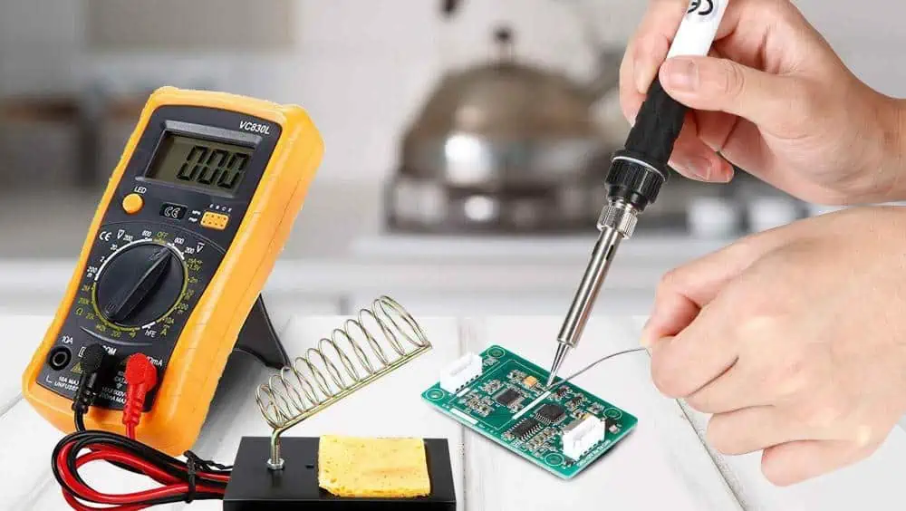
Soldering Iron
The soldering iron is your primary tool. Here are key factors to consider:
Temperature Control
- Low-end irons: Fixed temperature
- Mid-range irons: Adjustable temperature
- High-end stations: Precise digital control
Wattage
- 15-30W: Suitable for small components and delicate work
- 30-60W: Ideal for general-purpose PCB soldering
- 60W+: Necessary for large components or ground planes
Tip Types
| Tip Shape | Best Use Case |
| Conical | Precision work, small components |
| Chisel | General-purpose soldering |
| Bevel | Drag soldering, large pads |
| Hoof | Desoldering, removing solder |
Solder
Choosing the right solder is crucial for successful PCB soldering.
Composition
- Lead-based: Easier to work with, but environmental concerns
- Lead-free: Environmentally friendly, higher melting point
Diameter
- 0.5mm – 0.8mm: Fine pitch components
- 0.8mm – 1.2mm: General-purpose soldering
- 1.2mm+: Large components, heavy-duty work
Flux Core
Flux helps clean the surfaces and promote better solder flow. Most electronic solder comes with a flux core.
Other Essential Tools
- Desoldering pump or wick
- Flux pen or liquid flux
- Wire cutters and pliers
- Tweezers
- Magnifying glass or loupe
- Multimeter
- Fume extractor
Preparing for Soldering
Workspace Setup
- Choose a well-ventilated area
- Use a non-conductive, heat-resistant work surface
- Ensure good lighting
- Keep your work area clean and organized
Safety Precautions
- Wear safety glasses
- Use a fume extractor or work in a well-ventilated area
- Never touch the hot end of the soldering iron
- Wash hands after soldering to remove flux residue
PCB and Component Preparation
- Clean the PCB with isopropyl alcohol
- Inspect components for damage
- Pre-tin component leads if necessary
- Secure the PCB in a helping hand or PCB holder
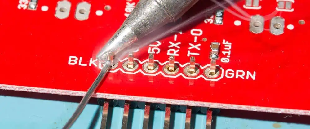
Basic Soldering Techniques
Through-Hole Soldering
- Insert the component into the PCB
- Bend leads slightly to hold it in place
- Heat the pad and lead simultaneously
- Apply solder to the junction, not the iron tip
- Remove heat and allow the joint to cool
- Trim excess lead length
Surface Mount Soldering
Drag Soldering
- Apply flux to the pads
- Align the component
- Tack one corner pin
- Verify alignment and adjust if needed
- Apply solder to the iron tip
- Drag the iron across the pins
- Use solder wick to remove bridges
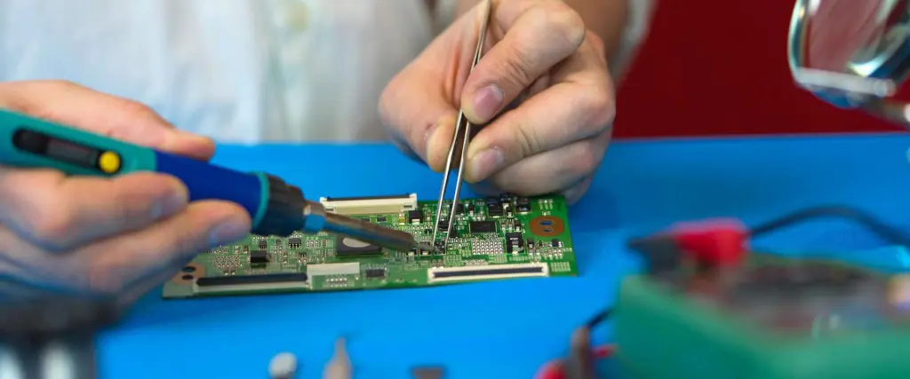
Individual Pin Soldering
- Apply flux to the pads
- Place the component
- Solder one corner pin
- Verify alignment
- Solder remaining pins individually
- Clean excess flux
Advanced Soldering Techniques
Fine-Pitch Components
- Use a fine-tip soldering iron
- Apply liquid flux
- Use minimal solder
- Consider using a hot air rework station for very fine pitch
BGA (Ball Grid Array) Rework
BGA soldering typically requires specialized equipment, but for repair:
- Apply flux to the BGA pads
- Align the BGA carefully
- Use a hot air rework station to reflow solder
- Allow to cool slowly
- Inspect with X-ray if possible
Desoldering Techniques
Using a Solder Sucker
- Heat the solder joint
- Place the solder sucker over the melted solder
- Quickly press the button to suck up the solder
- Repeat if necessary
Using Desoldering Wick
- Place the wick on the solder joint
- Heat the wick with the iron
- As the solder melts, it will be drawn into the wick
- Move to a clean section of wick and repeat if needed
Soldering Best Practices
Temperature Control
| Component Type | Recommended Temperature Range |
| Small components | 315°C – 340°C (600°F – 650°F) |
| General-purpose | 340°C – 370°C (650°F – 700°F) |
| Large components | 370°C – 400°C (700°F – 750°F) |
Tip Care and Maintenance
- Keep the tip tinned when not in use
- Clean the tip frequently using a damp sponge or brass wool
- Replace tips when they become pitted or deformed
Avoiding Common Mistakes
- Cold joints: Ensure proper heating of both the pad and component
- Overheating: Work quickly and efficiently
- Bridging: Use appropriate amount of solder and clean excess
- Disturbed joints: Allow joints to cool completely before moving
Inspection and Quality Control
Visual Inspection
Look for:
- Smooth, shiny solder joints
- Proper wetting and fillet formation
- No solder bridges or excess solder
- No visible damage to components or PCB
Electrical Testing
- Continuity testing
- Voltage and current measurements
- Functional testing of the circuit
Rework and Repair
If issues are found:
- Identify the problem
- Choose appropriate rework technique
- Re-solder or replace components as needed
- Re-inspect and test
Environmental Considerations
Lead-Free Soldering
- Higher melting point (requires higher temperatures)
- May require different flux formulations
- Can result in duller-looking joints (still functional)
Proper Disposal
- Recycle scrap PCBs and components
- Dispose of lead-containing solder as hazardous waste
- Follow local regulations for electronic waste disposal
Troubleshooting Common Soldering Issues
| Issue | Possible Causes | Solutions |
| Cold joint | Insufficient heat, movement during cooling | Reheat and add small amount of solder |
| Solder bridges | Excess solder, poor technique | Use solder wick to remove excess |
| Lifted pads | Overheating, mechanical stress | Secure pad, use jumper wire if necessary |
| Burned components | Excessive heat, poor heat sinking | Replace component, use heat sink clips |
| Dry joint | Contamination, insufficient flux | Clean thoroughly, add flux, resolder |
Continuing Education and Skill Development
- Practice regularly with various component types
- Stay updated on new soldering technologies and techniques
- Consider certification programs (e.g., IPC-A-610)
- Join electronics communities and forums for knowledge sharing
Conclusion
Manual PCB soldering is both an art and a science. With the right tools, techniques, and practice, you can achieve professional-quality results. Remember to prioritize safety, maintain your equipment, and continually refine your skills. Whether you’re working on prototypes assembly board, repairs, or small-scale production, mastering manual soldering will prove invaluable in your electronics journey.
Frequently Asked Questions
Q1: How do I choose the right soldering iron for PCB work?
A1: Consider factors such as adjustable temperature control, appropriate wattage (30-60W for most PCB work), and interchangeable tips. Look for models with good thermal recovery and a comfortable grip. For beginners, a mid-range soldering station with digital temperature control is often a good starting point.
Q2: What’s the difference between lead and lead-free solder for PCB work?
A2: Lead solder (typically 60/40 or 63/37 tin-lead) has a lower melting point, flows better, and is easier to work with. However, it’s being phased out due to environmental concerns. Lead-free solder (often SAC305) has a higher melting point, can be more difficult to work with, and may produce duller-looking joints, but it’s more environmentally friendly and compliant with modern regulations.
Q3: How can I prevent damaging sensitive components while soldering?
A3: Use temperature-controlled soldering irons, work quickly and efficiently, use heat sinks on sensitive component leads, and avoid overheating. For very sensitive components, consider using anti-static precautions. Always double-check the component’s maximum temperature rating and adjust your soldering technique accordingly.
Q4: What’s the best way to remove solder bridges between fine-pitch components?
A4: First, apply a small amount of flux to the bridged area. Then, use fine desoldering braid (wick) to remove the excess solder. Place the wick on top of the bridge and apply heat with your soldering iron. As the solder melts, it will be drawn into the wick. Move to a clean section of wick and repeat if necessary. For very fine pitch components, you may need to use a hot air rework station or a specialized fine-tip soldering iron.
Q5: How often should I clean and tin my soldering iron tip?
A5: Clean your tip frequently during use, ideally after every few solder joints. Use a damp sponge or brass wool for cleaning. Tin the tip (apply a small amount of fresh solder) whenever you set the iron down or finish a soldering session. This prevents oxidation and extends the life of your tip. Replace tips when they become pitted, deformed, or no longer hold solder properly.