
RAYPCB · Node · gateway · installation
LoRa antenna: budget the link before promising range
Match the antenna to the radio, region and installation. Separate feeder loss, directional gain and fade reserve with a transparent link-budget worksheet.
Preliminary layouts and open RF questions are welcome.
What is a LoRa antenna?
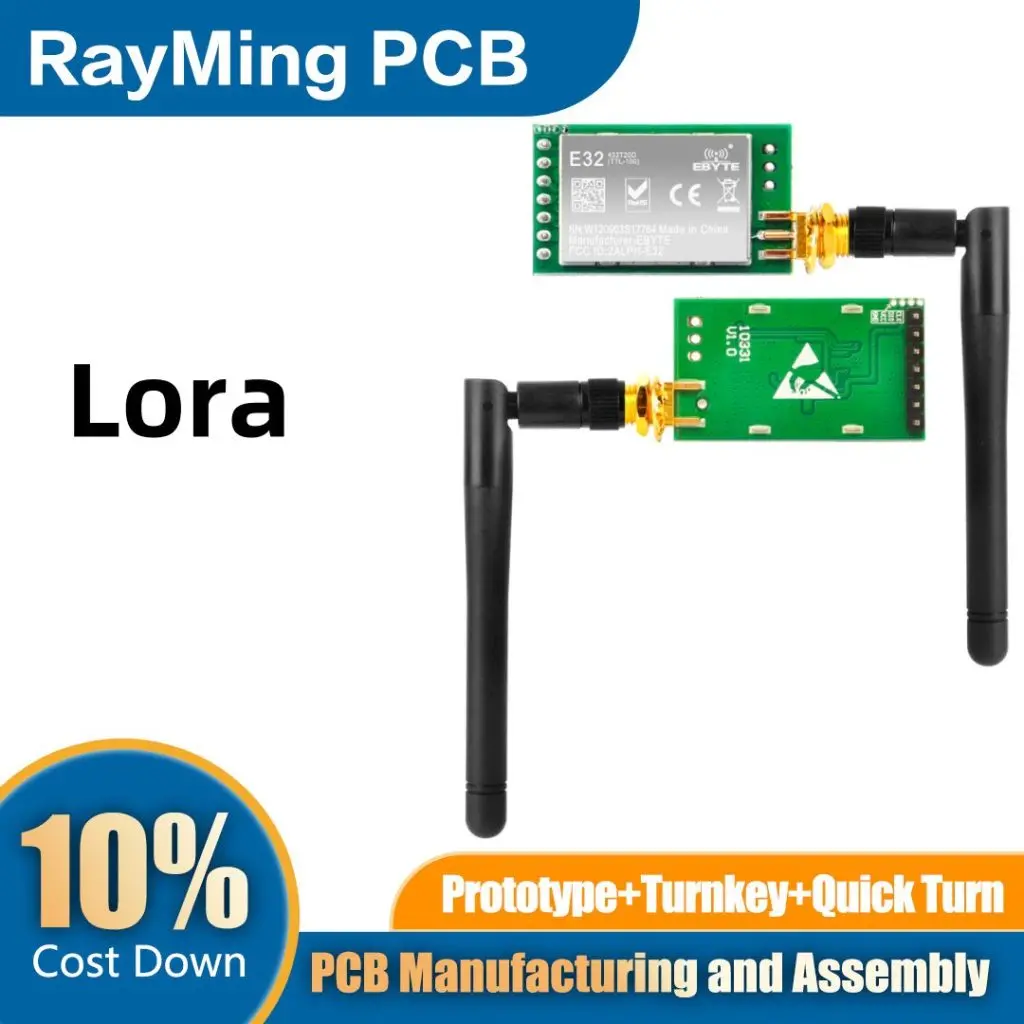
A LoRa antenna is an antenna selected for the operating band and installation of a LoRa radio system. LoRa describes the radio technology; it does not define one universal antenna frequency, shape or connector. A node and a gateway may need very different mechanical and directional characteristics even when they communicate on the same channels. Start with the exact radio, destination market, channel plan and product installation.
An antenna cannot be selected responsibly from an advertised distance alone. Range depends on conducted transmitter power, installed antenna patterns, feeder losses, receiver mode, interference, terrain and fading. A transparent link budget helps expose assumptions, while actual installed measurements determine whether the product meets its application requirement. The useful goal is reliable communication under stated conditions, not an unsupported maximum range claim.
This page owns LoRa antenna selection and link planning. Use 433 MHz PCB antenna design for the electrical-size and radiator problem at that band. For other structures or a fabrication enquiry, continue through the antenna PCB overview.
Select the band and installation before comparing gain
Write down the radio part, supported frequencies, required channels, connector and allowed antenna arrangement. Regional LoRaWAN parameters are a network reference, while legal frequency use and radiated-power conditions must be checked against the applicable local requirements. A frequency setting shown in a demonstration tool is not regulatory permission. Do not assume that a board sold for one region can be relabeled for another without reviewing its RF hardware and configuration.
The LoRa Alliance regional-parameters resource is an official reference for the named release. Confirm the revision relevant to your network and deployment. Semtech's LR1120 product and documentation page also illustrates why LoRa hardware should be identified by the exact device: supported bands and RF integration differ across products.
| Antenna route | Useful context | Integration evidence to request |
|---|---|---|
| Printed on the main PCB | A node with a suitable board edge and ground | Reference layout, installed efficiency and matching data |
| Separate FPC or small antenna board | Radiator positioned away from crowded electronics | Cable, adhesive, enclosure and reference-plane conditions |
| Helical or wire element | Product has controlled three-dimensional volume | Part tolerances, forming and assembly position |
| External whip or dipole | Enclosure or placement favors a separate radiator | Pattern, cable loss, connector and mounting instructions |
| Directional antenna | A defined fixed link or sector is required | Pattern alignment, installation tolerance and system limitations |
Ask whether published gain is peak gain, average gain, realized gain or a figure including a cable. These are not interchangeable. The link needs gain in the actual direction toward the other device, with the installed polarization and environment. A high peak gain can be unhelpful when the product points into a null or the gateway is above an antenna's useful elevation region.
Node and gateway antennas solve different problems
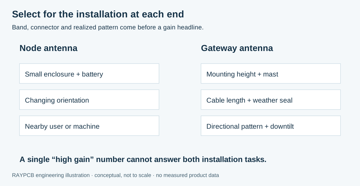
A node often has limited volume, battery proximity and changing orientation. Its antenna may be affected by a person, an enclosure wall or the surface to which the product is attached. A gateway may have more room but a longer feeder, a mast, weather sealing and a specific coverage objective. Specify both ends of the link instead of treating one generic antenna data sheet as a complete system design.
For an outdoor installation, include cable routing, connector sealing, mechanical retention and the relevant environmental requirements. These are procurement and reliability inputs as well as RF details. A laboratory antenna with an ideal cable position can behave differently after the cable is coiled beside a metal enclosure or routed along a mast. Keep the installed configuration in the test record.
For a PCB antenna, preserve the manufacturer's ground and keepout requirements. Do not fill its clearance with a mounting hole, debug connector or battery lead after RF tuning. For a purchased antenna, retain the part revision and integration instructions. A similar connector and nominal frequency do not prove that a substitute has the same installed pattern or matching behavior.
Build a link budget with visible assumptions
The worksheet combines entered conducted power, realized antenna gains, feeder losses, receiver threshold, excess propagation loss and fade reserve. It calculates free-space path loss for the stated distance and frequency, then shows the estimated received power and remaining margin. It also calculates the first Fresnel-zone radius at the midpoint. Every engineering input remains visible in the downloadable brief.
RAYPCB ENGINEERING
Antenna BandsLoRa Link Budget and Fresnel Screen
Loading LoRa Link Budget and Fresnel Screen…
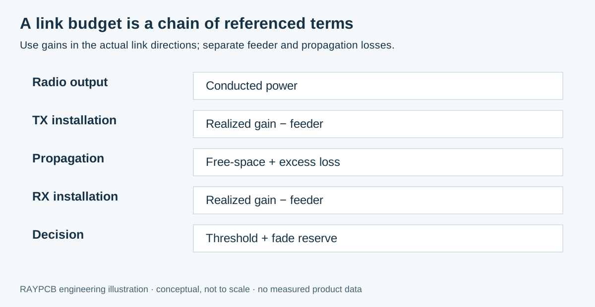
The illustrative 868 MHz, 2 km link uses 14 dBm conducted power, 1 dBi TX realized gain, 1 dB TX feeder loss, 2 dBi RX realized gain and 1 dB RX feeder loss. Free-space loss is approximately 97.24 dB. With an additional 20 dB allowance, estimated receive power is about −102.24 dBm. Against an entered −125 dBm threshold and 15 dB fade reserve, the remaining margin is approximately 7.76 dB. These are assumed inputs, not measured RAYPCB range data or a permitted-power recommendation.
Use receiver sensitivity for the exact mode and test conditions. Spreading factor, bandwidth, coding rate and implementation can change the relevant threshold. Do not combine a favorable sensitivity number from one setting with traffic or latency expectations from another. Record the data-sheet or measured basis rather than entering a value solely to make the budget positive.
Realized antenna gain already includes the antenna's radiation efficiency and mismatch under its stated conditions. In this worksheet, feeder loss refers to a separate path outside that antenna reference plane. Subtracting the same cable, mismatch or efficiency twice produces a misleading result. If the source data use a different definition, translate them to a consistent reference before comparing candidates.
Free space is a screen, not the deployment model
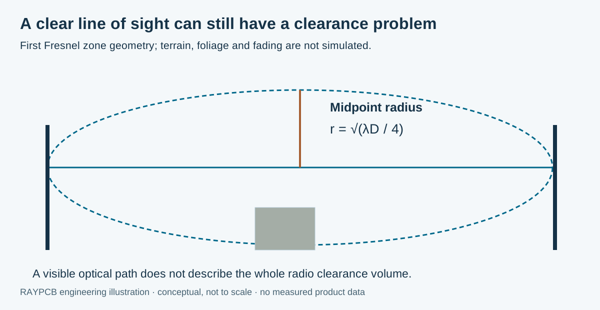
Free-space path loss is a useful far-field baseline. Buildings, foliage, terrain, ground interaction and moving obstructions can add losses or create fading that the simple formula does not predict. An excess-loss entry and fade reserve make assumptions visible; they do not turn the model into a site survey. Use terrain and installation information, followed by field measurements, for a deployment decision.
The midpoint first Fresnel radius is calculated as the square root of wavelength times total path length divided by four. It shows why a visually clear line can still have an important radio-clearance problem. The worksheet intentionally does not choose an automatic clearance percentage or approve a mast height. The appropriate criterion depends on the link and the engineering method used for the site.
Keep a negative margin visible. It indicates that the entered assumptions exceed the available budget. Review the actual cause: feeder loss, mounting, antenna direction, receiver mode or an unrealistic propagation assumption. Increasing transmitter power is not a universal solution and may be constrained by the radio, battery, interference objective or applicable rules.
Connect the antenna to a reproducible RF path
The radio reference design may include power-amplifier matching, receive matching, switching and filtering before the antenna port. Those networks serve different tasks from antenna tuning. Preserve their component placement and return paths, and identify any nominal controlled-impedance interface. A connector placed for convenience should not leave an unreviewed stub on the RF path.
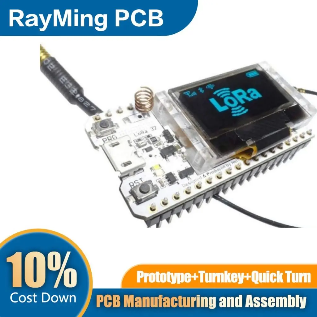
Specify the actual stackup beneath the feed. Overall board thickness is not enough to define a top-layer line on a multilayer board. Keep copper thickness, solder mask, reference plane and critical geometry consistent with the approved construction. The PCB impedance design guide can help examine a line, while the RF PCB page connects that geometry to fabrication choices.
Consider the rest of the product during layout. Switching supplies, clocks and other radios can affect reception; a strong transmitted signal can also disturb nearby circuitry. An IoT PCB needs power, firmware and coexistence planning alongside antenna work. If the product contains GNSS, use the GPS patch antenna guide for its separate receive-chain and interference requirements.
Measure communication under the actual operating policy
Define the application transaction, traffic, radio configuration and delivery requirement. A short uplink with occasional retries has a different operational profile from frequent bidirectional exchanges. Record where packet counts are taken, how duplicates are handled and whether acknowledgements or network behavior affect the result. Compare antenna candidates under equivalent settings and load.
Test the intended node orientations and gateway installation. Include weak but realistic locations, rather than selecting only the strongest path. Save timestamps and relevant environment notes so a later run can be interpreted. A change in network loading or interference can otherwise be mistaken for a hardware improvement.
| Evidence | Question answered | Important boundary |
|---|---|---|
| Feed measurement | Is the antenna port matched under the tested installation? | Does not establish radiation efficiency |
| Pattern or realized-gain measurement | Where does the installed antenna receive or radiate effectively? | Requires a defined antenna and fixture arrangement |
| Link-budget worksheet | Are the entered terms internally consistent? | Does not predict terrain or interference automatically |
| Field packet tests | Does the application work under the recorded deployment conditions? | Does not cover every future site or operating state |
For production, define a practical test correlated to the engineering requirement. Keep the antenna part, board revision, cable and matching population traceable. If a substitute changes the RF path or installation, review the affected evidence. A visual match between two parts is not an RF equivalence test.
Quote the complete node or antenna-board scope
A useful enquiry includes the radio, band, board outline, antenna route, quantity, enclosure and intended installation. State whether the order is a bare antenna PCB, a populated node or a larger assembly. Separate purchased antenna parts, cables, connectors, programming, tuning and verification. The PCB manufacturing service can then be scoped around concrete deliverables instead of a vague long-range claim.
Open optional hardware budget and RFQ brief
RAYPCB ENGINEERING
Antenna BandsAntenna Hardware Budget and RFQ Brief
Loading Antenna Hardware Budget and RFQ Brief…
The optional budget brief uses entered per-unit, setup and verification allowances. It contains no built-in current antenna prices and does not infer an approved production test from a link margin. If costs are unknown, leave them blank and send the technical brief. Attach the link calculation manually when it helps explain the intended installation; there is no automatic transfer into Contact.
LoRa antenna questions
Is LoRa always a sub-GHz system?
No. Supported frequencies depend on the particular radio and implementation, including products with 2.4 GHz capability. Identify the device and operating configuration before selecting the antenna. A LoRa label alone does not define its band.
Will a higher-gain antenna always improve coverage?
Not necessarily. The pattern and polarization must serve the actual link directions, and the installed system must remain within its applicable limits. Higher peak gain can trade coverage in one direction for reduced coverage elsewhere. Compare the required installation rather than the headline number.
Does positive link margin guarantee the stated distance?
No. It confirms only the arithmetic of the entered model. Unmodeled obstruction, interference, fading, orientation and receiver behavior can dominate a real deployment. Use the worksheet to prepare a testable budget, then verify the installation.
What can I provide before the final antenna is chosen?
Send the radio and region, required channels, available volume, enclosure and mounting concept, quantity and desired verification scope. A shortlist or unresolved question is sufficient to begin an engineering review. Mark uncertain gain and loss assumptions clearly.
Review a LoRa hardware requirement
Send the radio and antenna reference, board revision, intended bands, enclosure information and quantity. Include the measurements you have and the question you need to resolve.
Tool use is optional. Attach any downloaded brief manually; Contact does not automatically receive worksheet inputs. References reviewed September 2026. Illustrations are explanatory, and photographs are not process qualification records.