
RAYPCB · Sub-GHz integration notebook
433 MHz PCB antenna design: fit the product, then prove the band
Compare printed, wire and loaded antenna options against enclosure space. Inspect your measured S11 sweep and identify what a narrow resonance does—and does not—prove.
Preliminary layouts and open RF questions are welcome.
What is different about a 433 MHz PCB antenna?
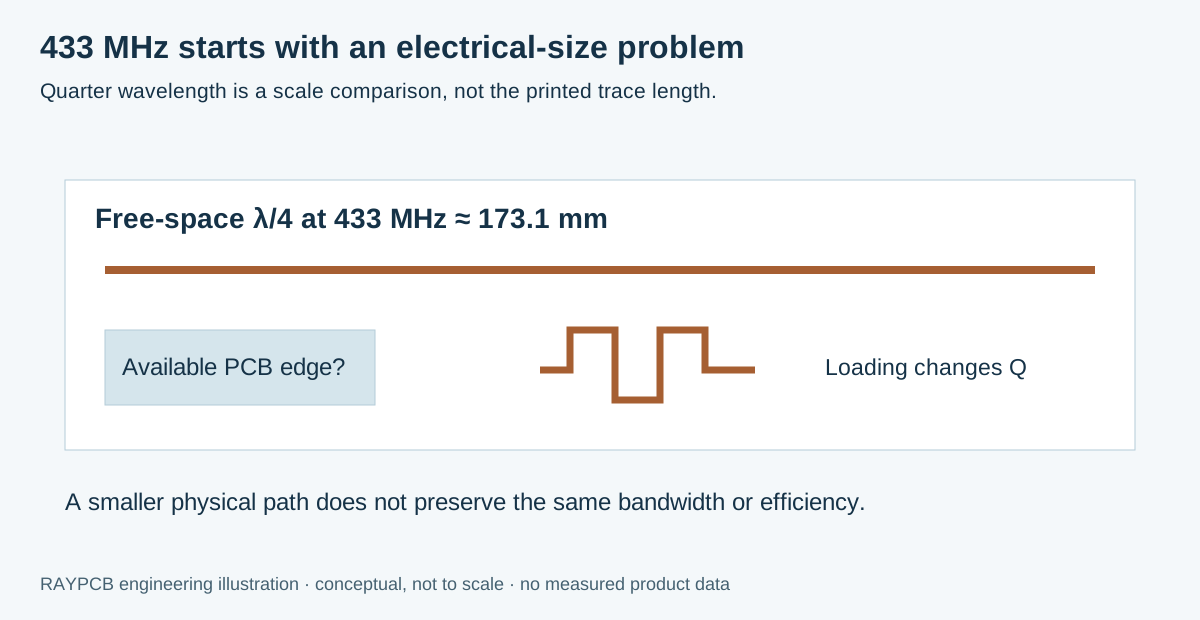
A 433 MHz PCB antenna must fit an electrically long wavelength into the product's available conductor, ground and surrounding space. At 433 MHz, a free-space quarter wavelength is approximately 173.1 mm. That is a scale reference, not a finished printed trace length. A compact meander, loaded loop or helical alternative can occupy less physical space, but its bandwidth, losses and installation sensitivity must be evaluated as a complete antenna structure.
Start with the required operating band, radio mode, product envelope and intended market. The phrase 433 MHz does not specify a permitted channel, transmit power or duty cycle for every location. It also does not tell you whether the product uses a proprietary narrowband link, a particular modulation or a LoRa implementation. Keep the hardware and applicable regional requirements separate until both have been defined.
This page focuses on size, radiator options and measured matched bandwidth. For LoRa link calculations and gateway-versus-node choices, use the LoRa antenna guide. The broader antenna PCB page remains the entry point for selecting antenna structures and discussing fabrication.
Reserve the antenna volume before the board is full
An antenna volume is more than an unused rectangle in a copper layer. It includes space above and below the radiator, nearby battery and enclosure surfaces, the ground structure, and the path of wires or connectors. A compact sensor can have enough area for a visible meander and still lack a suitable environment for that meander to radiate efficiently. Resolve that question while the enclosure and board outline can still change.
Draw the available PCB edge, ground extent and three-dimensional clearance. Add the intended mounting surface and likely orientation. A product screwed to a steel cabinet has a different boundary condition from the same board held in free space. If a wire antenna is an option, show its formed position and retention method. A loose wire that moves during assembly creates an uncontrolled RF variable.
Miniaturization changes the engineering tradeoff. Adding turns or loading can shift resonance, but can also concentrate stored energy and make the response more sensitive to tolerances and nearby materials. Do not use low reflected power at one frequency as proof that a small antenna retains useful efficiency. Include a radiated measurement or a justified system-level test plan in the comparison.
Compare printed, helical and external routes fairly
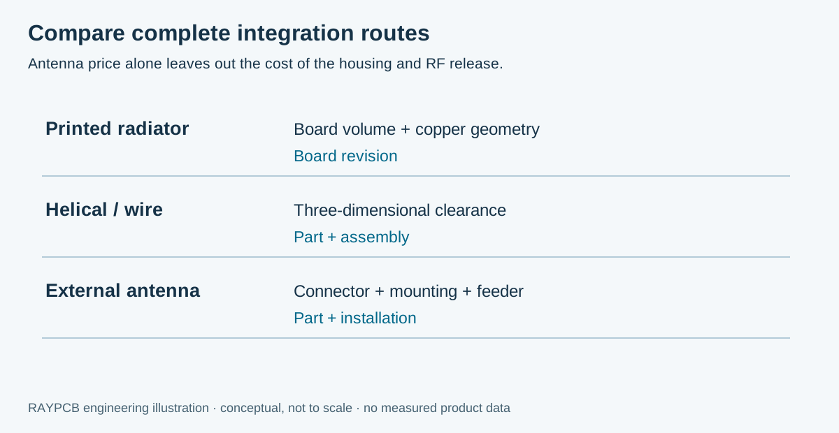
| Route | Attractive when | Cost or integration question |
|---|---|---|
| Printed board antenna | The product can reserve an appropriate board and ground region | Will antenna area or tuning iterations dominate the saving in parts? |
| Helical or wire element | Three-dimensional volume is available | How will the element position be controlled during assembly? |
| Purchased chip antenna | A qualified integration reference matches the product | What host ground and clearance are required beyond the component body? |
| External antenna | The radiator needs separation from a restrictive enclosure | What do the connector, cable, seal and installation add? |
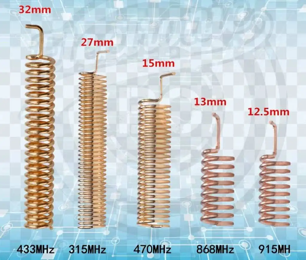
The old-page wire photograph illustrates why physical length labels need context. Two antennas marked for the same frequency can use different conductor paths, loading and ground assumptions. A spring's compressed height is not its conductor length, and neither is a universal layout dimension for a PCB antenna. Use the part drawing and measured reference configuration when evaluating a purchased element.
Texas Instruments' antenna selection guide is a useful primary source for comparing different reference implementations. Its examples support a structured selection process rather than a claim that one radiator is best for every small product. Preserve the relevant reference geometry and record what changes in your installation.
Read the useful band from an S11 sweep
The band reader accepts a small numeric CSV with frequency in MHz and S11 in dB. Set the required lower and upper frequencies and an engineering threshold. The worksheet interpolates threshold crossings between samples, keeps separate below-threshold intervals separate, and reports whether the requested band fits inside one interval. It also identifies the largest sample spacing so the limitations of a sparse sweep remain visible.
RAYPCB ENGINEERING
Antenna Bands433 MHz S11 Band Reader
Loading 433 MHz S11 Band Reader…
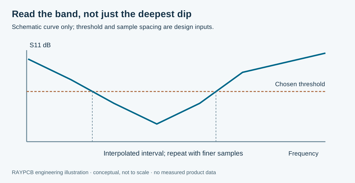
The illustrative data cross a −10 dB threshold at approximately 431.0 and 436.8 MHz. That gives a sampled-model interval of 5.8 MHz. The example requested band lies within that interval, but this does not approve a regional operating allocation or prove radiation efficiency. Replace the demonstration with measurements of your actual board, fixture and installed condition.
Crossings are interpolated linearly in dB. A narrow feature between samples may be missed, and an interval ending at the first or last sample is clipped by the sweep rather than proven to end there. Increase frequency resolution and extend the sweep when needed. The chosen −10 dB example is not a universal pass limit; use a requirement supported by your radio, system budget and validation method.
The tool also shows free-space quarter wavelength at the requested band's center. That value helps compare electrical scale with enclosure space. It does not apply a generic dielectric shortening factor to an arbitrary printed antenna or turn the result into a cutting instruction. Printed and loaded structures need their own current distribution and installation model.
Match the complete reference, not its headline frequency
Before reusing an antenna, obtain the complete reference design: board outline, ground shape, stackup, radiator geometry, matching network and measurement setup. A reference tuned on one ground size may shift when moved to another board. Changing the feed or solder-mask coverage can matter as well. List differences explicitly so that the first prototype tests a clear hypothesis.
The TI application note 433–930 MHz and 2.4 GHz BOM-tunable PCB antenna demonstrates a defined reference approach spanning several configurations. The useful lesson is that geometry, component population and operating configuration belong together. It is not permission to apply a matching BOM from one band to an unrelated radiator or radio.
Keep radio-output matching, filtering and antenna tuning distinct in the schematic. A transceiver may require a device-specific network before reaching its intended antenna interface. Provide tuning footprints and measurement access without leaving uncontrolled branches on the RF path. If a temporary coaxial connection is used, document how the radio is disconnected and where the instrument reference plane ends.
For the feed and layer construction, review controlled impedance in PCB design. A controlled line makes the connection reproducible; it does not establish the radiation behavior of the antenna connected to it. The distinction becomes especially important when a good feed calculation is used to justify an antenna that has never been measured in its enclosure.
The housing and the installer are part of the test
Evaluate a realistic installed product, including battery, display, wiring, potting, fasteners and mounting bracket. If the product is touched or carried, include representative user proximity. If it is mounted on metal, reproduce that mounting condition. Test the expected orientations and record which direction has the weakest usable link. A single favored orientation should not become the advertised system range.
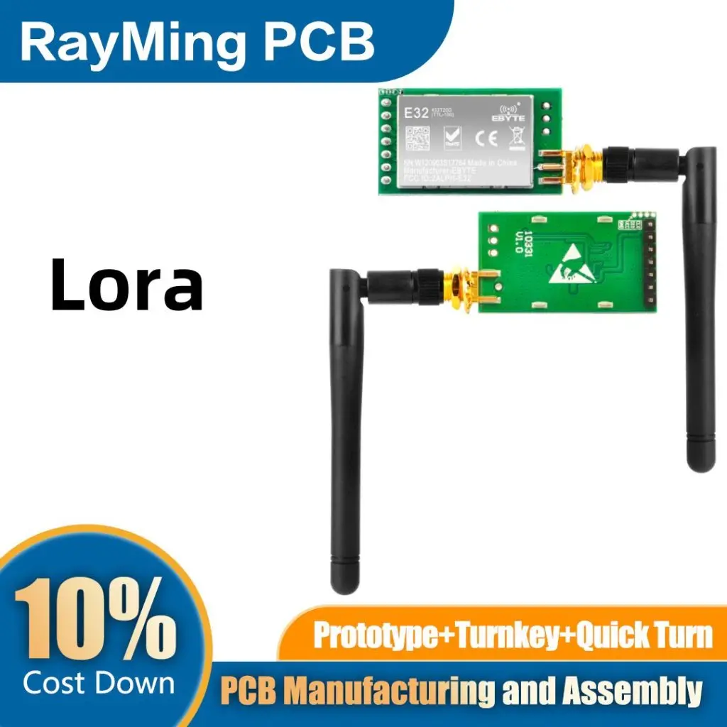
For an external antenna, identify the connector and cable reference planes. State whether the antenna gain data include any attached cable. Avoid subtracting a feeder loss twice or mixing an antenna's free-space peak gain with a different installed orientation. The cable can also affect the current distribution if the antenna system lacks the intended balance or counterpoise.
A controlled comparison holds radio settings, distance, test location and logging rules constant while changing one physical condition. Packet delivery can reveal a product-level problem, but does not identify whether it came from mismatch, efficiency, interference or software. Combine system observations with appropriate RF measurements before choosing a corrective action.
Release what the tuned hardware actually contains
The fabrication release should preserve the approved antenna copper, keepout, ground, dielectric and outline conditions. The assembly release should preserve matching part values, packages, permitted substitutes and antenna mounting. Include any wire-forming drawing, connector orientation and strain relief. These are functional requirements when they affect the RF structure, even if they look like minor assembly details.
Use clearly marked variants for prototype comparisons. If three radiator or matching versions are ordered, identify them in the drawing, assembly BOM and sample labels. Do not mix them into one batch with handwritten assumptions that disappear before testing. The PCB prototype manufacturing page describes the broader release preparation for first builds and revisions.
Decide which checks belong at incoming inspection, board test and final product test. A continuity check can identify an open conductor; it cannot demonstrate antenna bandwidth or radiated performance. If production RF screening is required, define the fixture, conditions and correlation to the engineering acceptance method. A fixture that is convenient for production still needs evidence that its result is meaningful.
Compare the cost of an approved installation
The lowest component count is not necessarily the lowest development or production cost. A printed antenna can consume board area and engineering iterations. A helical part can add placement and forming variation. An external antenna can add cable and enclosure work while making the RF integration easier. Compare these alternatives at the same quantity and test scope, with the same responsibilities for supplied parts and final assembly.
Open optional hardware budget and RFQ brief
RAYPCB ENGINEERING
Antenna BandsAntenna Hardware Budget and RFQ Brief
Loading Antenna Hardware Budget and RFQ Brief…
Use entered allowances to separate per-unit hardware, setup and batch verification. The tool contains no current market rates and gives no automatic price for a loaded antenna. If you do not have dated cost evidence, leave all cost fields blank and download the technical scope only. Send the available envelope, target band, radio, quantity and measurements through Contact for a concrete engineering review.
Manufacturing scope can be discussed through PCB manufacturing, while material and RF construction questions belong with RF PCB. A useful enquiry states whether the unresolved issue is antenna placement, reproducibility, assembly or measurement, so the response can focus on the real next decision.
433 MHz antenna questions
Should I make the trace exactly 173 mm long?
No. That is approximately a free-space quarter wavelength at 433 MHz, useful for scale only. A printed antenna's geometry, ground, loading and surroundings determine its behavior. Use a suitable reference, modeling and final installed measurements rather than one universal trace length.
Does a deep S11 dip mean the antenna is efficient?
No. Low reflection indicates power is accepted at the measured port, but some accepted power can be dissipated rather than radiated. Evaluate appropriate efficiency, gain or system evidence, and preserve the measurement reference plane and installed condition.
Can the same antenna be used for every sub-GHz band?
Only if its actual performance and matching support the required bands in the intended product. A broad frequency label, similar connector or adjustable matching footprint does not establish that. Verify the full operating configuration and applicable regional requirements.
What data make a review productive?
Send the target frequencies, radio part and mode, board and enclosure drawings, proposed antenna reference, stackup and any calibrated sweep. Include the battery, mounting condition, quantity and required verification scope. Identify missing information instead of guessing a value to complete the form.
Discuss a 433 MHz antenna prototype
Send the radio and antenna reference, board revision, intended bands, enclosure information and quantity. Include the measurements you have and the question you need to resolve.
Tool use is optional. Attach any downloaded brief manually; Contact does not automatically receive worksheet inputs. References reviewed September 2026. Illustrations are explanatory, and photographs are not process qualification records.