
RAYPCB · ENGINEERING GUIDE
Solder Mask Opening Design: Pads, Clearance and Registration
A solder-mask opening defines where the permanent coating leaves a board surface exposed. Good opening design starts with the copper land, component requirements and mask process, then checks how variations change the remaining clearance. Increasing every opening by the same amount is not a complete design rule.
This guide focuses on the opening you intend to manufacture. For the numerical setting inside CAD rules, continue to solder-mask expansion. Stencil apertures belong to a different layer and are covered in the paste-mask comparison.
Identify the boundary that controls the joint
For a non-solder-mask-defined land, the copper edge usually establishes the solderable land boundary and the mask opening is larger. For a solder-mask-defined land, mask intentionally overlaps copper and contributes to the exposed boundary. These are deliberate land-pattern choices. They should follow the exact package and assembly requirements rather than a blanket preference for one abbreviation.
An opening over a via is another task. It may provide access or leave a feature exposed, but it does not automatically describe filling, plugging or tenting. Keep the via-treatment note separate. A board can contain several opening strategies, provided each is intentional and can be interpreted from the release data.
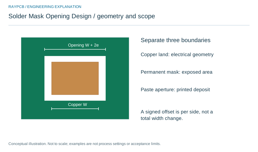
Rectangular mask-opening geometry
Rectangular mask-opening geometry
Use the current inputs and keep the assumptions
Start with the feature or process question you actually need to resolve. Fields are blank until you enter values or deliberately load an illustrative example. Example mode remains labeled after editing, so a sample is not silently presented as verified project data. Clear the example before preparing a project-specific record.
Use the units printed beside each input. Keep the drawing revision, measurement basis and source of any allowance in your controlled project records. A field that asks for a limit expects your agreed requirement; the example is not an IPC threshold or a statement of RAYPCB capability. A numerical result should lead to a focused review, not replace it.
Changing any input invalidates the displayed result and disables its download until you calculate again. The text download contains the current inputs, results and assumptions. Nothing is uploaded, stored in analytics or automatically transferred into the Contact form. You may attach the file manually if it helps explain your enquiry; completing the worksheet is optional.
| Input | What to establish before using it |
|---|---|
| Review reference | Use a nonconfidential reference to connect this worksheet to the correct design or process revision. |
| Copper land width · mm | Use the reference land dimension from the exact footprint. |
| Copper land length · mm | The model assumes an ideal rectangle, not a polygon or rounded corner. |
| Signed radial expansion · mm | Positive enlarges each side; negative contracts the opening and may intentionally overlap copper. |
Draw nominal geometry before adding variation
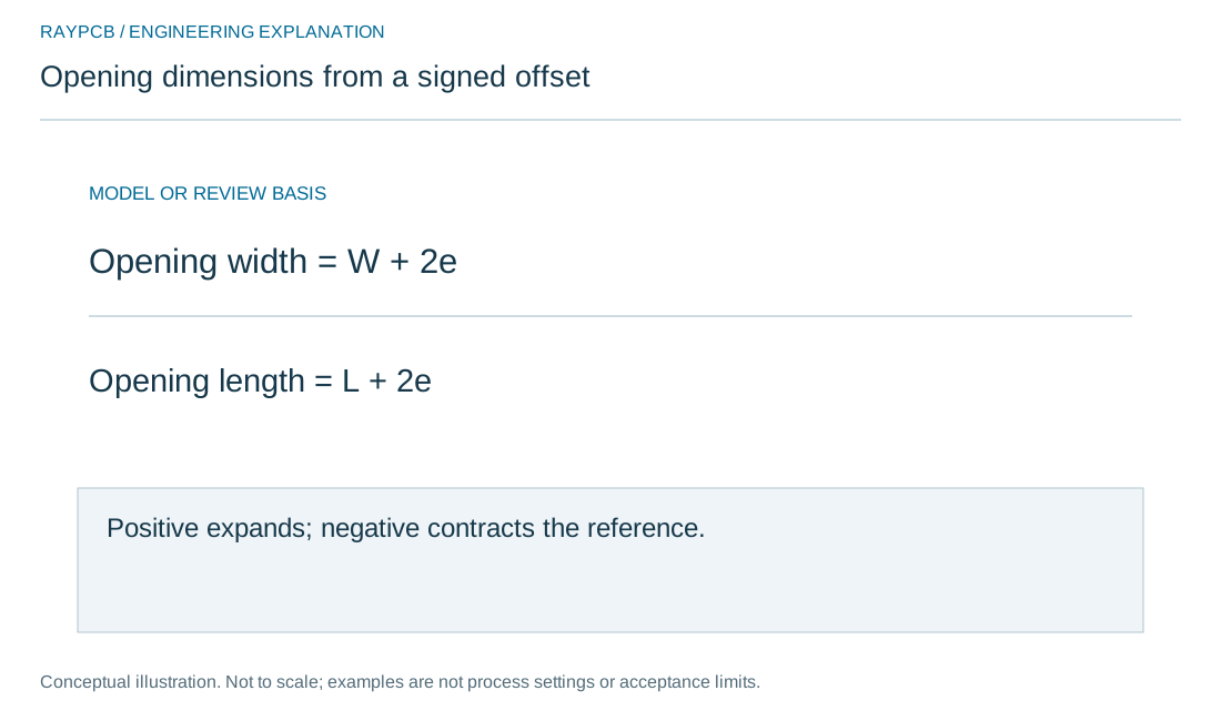
For a rectangular copper land of width W and length L, a uniform signed radial expansion e gives an ideal opening of W + 2e by L + 2e. Positive expansion enlarges it; negative expansion reduces it. The worksheet applies that geometry and rejects zero or negative opening dimensions. Real shapes with arcs, chamfers or irregular polygons need their actual CAD boundary checked.
Do not confuse a radial expansion with a total width increase. A requested total increase of 0.10 mm corresponds to 0.05 mm on each side in this simple model. Record whether a quoted clearance refers to nominal data, a manufactured minimum or an inspection result. Those three numbers are not interchangeable.
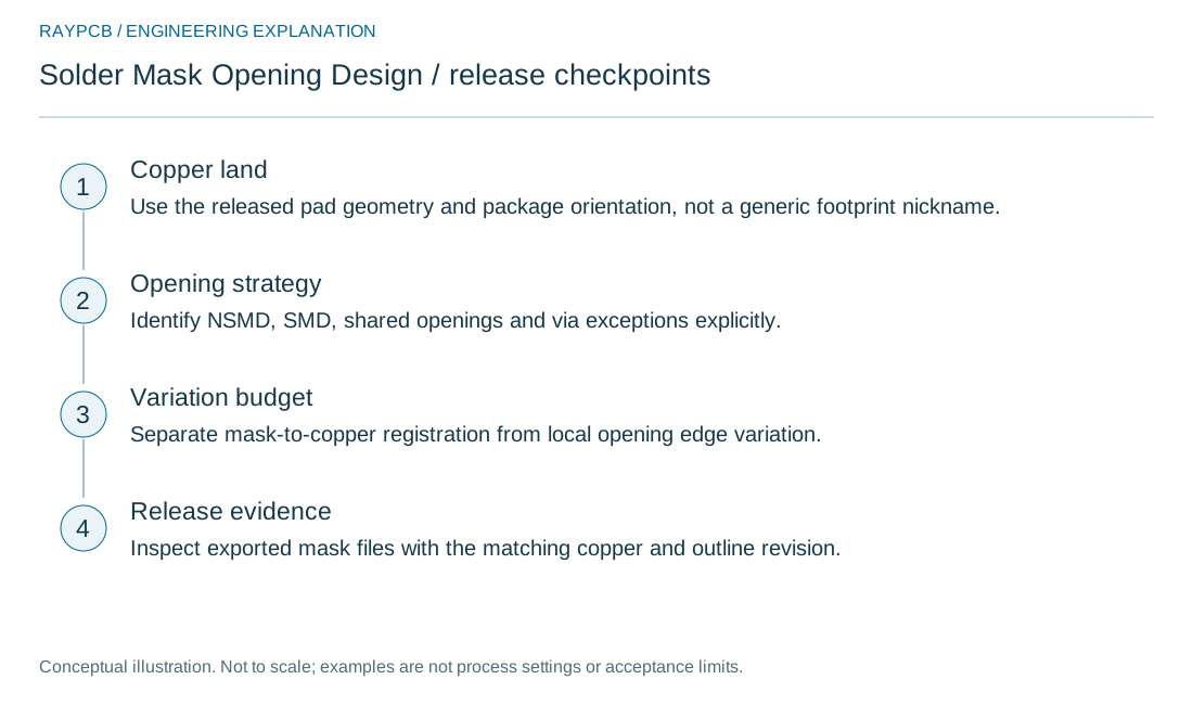
| Review item | What to establish |
|---|---|
| Copper land | Use the released pad geometry and package orientation, not a generic footprint nickname. |
| Opening strategy | Identify NSMD, SMD, shared openings and via exceptions explicitly. |
| Variation budget | Separate mask-to-copper registration from local opening edge variation. |
| Release evidence | Inspect exported mask files with the matching copper and outline revision. |
Separate registration from local opening growth
Registration describes where the mask image lies relative to copper. A common translation can reduce clearance on one side of a pad while increasing it on the other. Local opening growth or edge variation changes the size of an opening. These effects should be reviewed separately so the same allowance is not added twice.
For two adjacent openings, common translation of both does not by itself change the web between them. Local edge growth can consume that web. The solder-mask bridge design page addresses this second relationship. A design can have an adequate web between openings and still have poor clearance to the copper beneath it.

Decide when a shared opening is appropriate
Individual openings retain mask between lands only if the geometry and process support that web. A shared opening removes the intervening mask intentionally. It can be a practical design choice for a particular package, but it changes soldering conditions and must be reviewed with stencil aperture, paste deposition and component alignment.
Do not treat a fabricator's proposal to remove an unmanufacturable web as a silent data cleanup. Ask for the affected locations and review the assembly consequence. If a change is accepted, retain it with the released revision. Repeating a manufacturing edit outside the controlled CAD source can create different results on a later supplier or revision.
Check the exported data, not only the editor
Review the actual top and bottom mask outputs against copper, board outline, holes and component orientation. Confirm file polarity and layer identity in a viewer that interprets the export correctly. Display colors in the editor are not a specification of film coverage. Keep an image or report of the critical package regions in the release checklist.
Object overrides, library pad stacks and rule priorities can produce a result different from a board-wide value. Inspect a fine-pitch region, a large thermal land and a representative via family. This targeted review catches more meaningful mistakes than checking only a settings dialog and assuming all objects obey it.
Use a drawing note with a measurable scope
A useful note states the required opening strategy, exceptions and the basis for any permitted manufacturing adjustment. It should not prescribe an arbitrary universal minimum that conflicts with the selected mask material or registration process. Ask the fabricator which locations need review using the actual board data and intended finish.
The note can identify critical regions where mask overlap is prohibited or deliberately required. Tie those statements to component or net locations. Avoid vague requests such as perfect alignment everywhere without a defined tolerance or inspection method. The engineering question is the margin remaining at the feature that controls function.
Resolve the assembly consequence before release
An opening change can affect exposed copper, flux access, solder distribution and inspection visibility. Review thermal lands and close-pitch components with the assembly team before approving a global expansion change. A small file edit may be low effort in CAD but consequential for the solder joint.
For a review, send the mask and copper layers, exact package land pattern, a marked problem region and the intended construction. State which dimensions are fixed by the component supplier and which are open to discussion. This allows a focused manufacturing response while preserving ownership of the original electrical and assembly design.
Review one critical footprint through the complete file chain
Choose a representative footprint whose geometry makes the mask decision important. Place its component recommendation, copper land, mask opening and paste aperture side by side. Name the role of each boundary before comparing dimensions. This prevents an aperture change intended for printing from being applied to the permanent coating by mistake.
Next, identify the source of every allowance. Nominal expansion, local opening growth and mask-to-copper registration describe different effects. A conservative tolerance budget can be appropriate, but only when it does not count the same variation twice. If the source of an allowance is unknown, preserve that as an open question instead of treating a familiar round number as verified process data.
Inspect the final exported files for that footprint and at least one important exception. This is where object overrides, library differences and rule scope become visible. The released output should match the documented design choice. A manufacturing partner's proposed change should be tied to the same feature and revision so both sides can assess its effect on assembly.
For a repeat order, retain the approved file set and any accepted exception. If a new supplier or mask grade is proposed, review the critical geometry against that route rather than assuming the old nominal dimensions are universally producible. The objective is a stable functional interface, not the smallest possible number in a capability table.
The enquiry can be brief: the marked region, exact component, relevant layers and the decision you need to make. That gives the reviewer enough context to discuss a real margin or opening strategy without forcing the customer to complete an unrelated cost calculator first.
Standards, source context and limits
Use the official references for their stated scope and the applicable controlled document for contractual requirements. A public scope page, product description or application note is not a complete acceptance specification. Material-supplier guidance applies to the named material and process; it is not evidence that every option is available for this board.
Agree the document revision, construction, inspection method and any exceptions with the responsible engineering and quality teams. The explanatory drawings and worksheet examples on this page are original planning aids, not factory records, qualification results or compliance certificates.