Flexible printed circuit boards (flex PCBs) have revolutionized electronic design by enabling compact, lightweight, and dynamic applications that traditional rigid PCBs cannot support. However, the delicate nature of these flexible circuits presents unique challenges when it comes to soldering. Improper soldering techniques can lead to costly failures including cracks, delamination, and broken connections. This comprehensive guide will walk you through the essentials of properly soldering flex PCBs to ensure durable, reliable connections and avoid common pitfalls that plague even experienced technicians.
Understanding Flex PCBs and Their Unique Properties
What Is a Flex PCB?
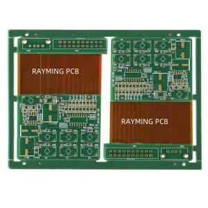
A flex PCB is a printed circuit board manufactured using flexible base materials, typically polyimide (like Kapton) or polyester films, with conductive traces of copper applied to these flexible substrates. Unlike their rigid counterparts, flex PCBs can bend, fold, and twist, making them ideal for applications where space is constrained or movement is required.
Key Differences Between Flex and Rigid PCBs
When comparing flex PCBs to traditional rigid boards, several critical differences impact the soldering process:
- Material Properties: Flex PCBs use heat-sensitive polymer films that can warp, melt, or delaminate under excessive heat.
- Thermal Expansion: Flex materials expand and contract at different rates than rigid boards, creating potential stress points during thermal cycling.
- Thickness: Flex PCBs are significantly thinner (often 0.1mm-0.2mm) than rigid boards, making them more susceptible to heat damage.
- Copper Flexibility: The copper traces on flex circuits are designed to withstand bending but can develop microcracks when subjected to improper heating during soldering.
Why Soldering Flex PCBs Requires Special Techniques
The unique properties of flex PCBs create specific challenges:
- Their thin, flexible nature makes them prone to warping under heat
- The thermal sensitivity of the base materials requires precise temperature control
- The dimensional instability during heating can cause misalignment of components
- Mechanical stress during handling can compound thermal stress from soldering
Understanding these fundamental differences is essential before attempting to solder flex PCBs. With this knowledge in mind, let’s explore the tools and materials you’ll need for successful flex PCB soldering.
Essential Tools and Materials for Flex PCB Soldering

Specialized Soldering Equipment
For optimal results when soldering flex PCBs, consider investing in:
- Temperature-controlled soldering iron: Look for models with digital temperature displays and quick recovery times
- Fine-tipped soldering tips: Precision tips (0.5mm or smaller) allow for accurate work on delicate traces
- Hot air rework station: For SMD components and areas requiring controlled, distributed heat
- Preheating platform: Helps minimize thermal shock and reduces the temperature differential during soldering
Recommended Solder Types and Flux
The right consumables make a significant difference:
- Low-temperature solder: SAC305 (96.5% tin, 3% silver, 0.5% copper) or similar lead-free alloys with melting points around 217°C
- Fine-gauge solder wire: 0.5mm or thinner diameter wire for precision work
- No-clean flux: Specifically formulated for flexible circuits with minimal residue
- Liquid flux pen: For precise application to small areas
- Flux remover: Compatible with polyimide and other flex substrates
Workstation Setup for Success
Proper preparation of your workspace helps prevent damage:
- ESD-safe environment: Anti-static mats, wrist straps, and ionizers to prevent electrostatic discharge
- Magnification: Illuminated magnifiers or microscopes (10-30x) for precision inspection
- Supporting fixtures: Non-conductive materials to support the flex during soldering
- Proper lighting: Shadow-free, adjustable lighting to clearly see small components
- Thermal management tools: Heat sinks or heat-resistant tape to protect sensitive areas
With your equipment prepared, the next step is understanding how to properly handle and prepare flex PCBs before soldering begins.
Preparing for Soldering: Handling and Inspection
Safe Handling Techniques for Flex PCBs
Improper handling before soldering even begins can damage flex circuits:
- Always support the entire flex PCB during handling to prevent bending in unintended areas
- Use clean, lint-free gloves to prevent oils and contaminants from affecting solder adhesion
- Avoid creasing or folding the flex material beyond its specified bend radius
- Transport and store flex PCBs flat or on curved surfaces matching their intended configuration
- Minimize the number of flex operations before soldering to prevent fatigue stress
Surface Preparation and Cleaning
Proper cleaning is critical for successful soldering:
- Use isopropyl alcohol (90%+ concentration) and lint-free wipes to remove oils and contaminants
- Allow the flex PCB to completely dry before soldering to prevent trapped moisture
- Avoid abrasive cleaning methods that could damage the thin copper traces
- For oxidized pads, use a specialized PCB cleaner designed for flex materials
- Inspect the cleaned surface under magnification to ensure all residues are removed
Pre-Soldering Inspection Checklist
Before applying heat, verify:
- All components match the design specifications for flex applications
- The flex circuit shows no signs of damage, delamination, or scratched traces
- Pads and traces are free from oxidation and contaminants
- The circuit is properly supported to prevent movement during soldering
- Temperature settings on equipment are appropriate for the specific flex material
- Test components are correctly oriented and positioned
With proper preparation complete, you’re ready to begin the actual soldering process.
Step-by-Step Guide to Soldering Flex PCBs
Step 1: Preheat the Flex PCB (When Necessary)
Preheating is often essential for flex PCB soldering:
- Why preheating matters: It reduces thermal shock, minimizes warping, and improves solder flow
- Safe temperature ranges: Typically 80-120°C, always below the glass transition temperature of the flex material
- Preheating methods:
- Use a dedicated preheating platform set to the appropriate temperature
- Allow gradual warming for 2-3 minutes before soldering
- Monitor the temperature with a non-contact infrared thermometer
- Ensure even heating across the entire flex PCB
Step 2: Position and Secure Components
Proper positioning prevents stress during soldering:
- Use heat-resistant tape or specialized fixtures to hold components in place
- Support the flex material completely to prevent unintended bending during heating
- For double-sided assemblies, secure components on one side before soldering the other
- Ensure components sit flat and are properly aligned with pads
- Avoid placing excessive pressure on the flex material when securing components
Step 3: Apply Flux Correctly
Flux application is critical for clean, strong joints:
- Apply a small amount of no-clean flux to the pads using a precision applicator
- Avoid excess flux that could spread to unwanted areas or be difficult to remove
- For sensitive areas, use a flux pen to target specific pads
- Remember that flex circuits often require more flux than rigid boards due to their thermal properties
- Allow the flux to activate briefly before applying solder
Step 4: Solder with Precision and Speed
The actual soldering process requires careful technique:
- For hand soldering:
- Set your soldering iron to the lowest effective temperature (typically 260-290°C)
- Touch both the pad and component lead simultaneously
- Apply solder to the junction of the tip, pad, and component
- Complete each joint quickly (1-2 seconds of contact)
- Move methodically to distribute heat evenly across the flex circuit
- For reflow soldering:
- Use a gentler temperature profile than for rigid PCBs
- Extend the preheat phase to allow for gradual temperature increase
- Reduce the peak temperature by 5-10°C compared to rigid board profiles
- Ensure cooling is controlled and gradual
- For hot bar soldering:
- Use dedicated flex-compatible hot bar equipment
- Apply uniform pressure across the connection
- Minimize dwell time to prevent overheating
Step 5: Inspect Solder Joints Thoroughly
Quality inspection prevents failures:
- Use magnification to examine each joint for proper wetting and formation
- A good solder joint on a flex PCB should be smooth, concave, and bright
- Look for signs of overheating such as discoloration of the substrate
- Check for cold joints, which appear dull and rough
- Verify no solder bridges exist between adjacent pads
- Ensure there is no evidence of damaged or lifted pads
Read more about:
Advanced Tips for Preventing Cracks and Failures
Managing Thermal Stress
Thermal management is crucial for flex PCB durability:
- Allow the assembly to cool naturally; never force cool with compressed air
- Use heat sinks to protect sensitive components and areas
- Consider staggered soldering patterns to distribute heat more evenly
- Allow cooling periods between soldering multiple joints in close proximity
- For complex assemblies, solder in zones moving from the center outward
Mechanical Support Techniques
Proper support prevents mechanical damage:
- Use silicone or Kapton tape to create strain relief at transition points between rigid and flex areas
- Apply conformal coating to provide additional support and protection
- Consider stiffeners in high-stress areas where components are mounted
- Design soldering fixtures that support the natural contours of the flex circuit
- Avoid creating sharp bends near solder joints
Protective Measures for Long-Term Reliability
Post-soldering protection extends service life:
- Apply appropriate conformal coatings compatible with flex materials
- Use strain relief features at connection points and transition zones
- Consider encapsulation for high-reliability applications
- Implement underfill for larger components to distribute mechanical stress
- Design cases or enclosures that prevent excessive bending at solder joints
Common Mistakes and Troubleshooting

Overheating the Flex Material
Signs and solutions for heat damage:
- Symptoms: Discoloration, bubbling, or delamination of the flex material
- Prevention: Use lower temperatures and shorter contact times
- Solution: For minor damage, inspect for electrical continuity; for severe cases, the affected section may need replacement
Excessive Mechanical Stress
Managing physical damage:
- Symptoms: Cracked solder joints, lifted pads, or broken traces
- Prevention: Proper support during soldering and handling
- Solution: Repair damaged traces with conductive epoxy; use reinforcement patches for structural integrity
Using Inappropriate Solder or Flux
Material compatibility issues:
- Symptoms: Poor wetting, cold joints, or excessive residue
- Prevention: Use only flex-compatible, low-temperature solders and fluxes
- Solution: Remove improper solder completely and reapply correct materials
Advanced Techniques for Complex Flex PCB Assemblies
Laser Soldering for High-Precision Applications
When ultimate precision is required:
- Laser soldering provides extremely controlled heat application
- Ideal for densely populated flex circuits
- Minimizes heat-affected zones around delicate areas
- Especially useful for medical and aerospace applications
- Requires specialized equipment and training
Heat Staking Methods
For securing components mechanically:
- Heat stakes create mechanical bonds in addition to electrical connections
- Provides additional support for components on flex circuits
- Reduces reliance on solder joint strength alone
- Particularly useful for high-vibration environments
- Can be combined with traditional soldering for maximum reliability
Adhesive Reinforcement Strategies
Combining adhesives with solder:
- Use specialized conductive adhesives for extremely heat-sensitive areas
- Apply non-conductive structural adhesives around large components for support
- Consider “dot and fill” techniques where adhesive dots secure components before soldering
- Implement underfill for larger components to distribute mechanical stress
- Use edge bonding to further secure components against shock and vibration
Conclusion: Mastering the Art of Flex PCB Soldering
Soldering flex PCBs successfully requires understanding their unique properties and adapting techniques accordingly. By following the guidelines in this comprehensive guide, you can avoid the common pitfalls of cracked joints, delamination, and thermal damage that often plague flexible circuit assemblies.
Remember that patience and precision are your greatest allies when working with these delicate yet powerful components. Proper equipment, careful temperature control, and meticulous attention to detail will result in reliable, long-lasting connections that maintain the integrity of your flex PCB designs.
As flexible electronics continue to expand into new applications from wearable technology to automotive systems, mastering these specialized soldering techniques will become an increasingly valuable skill for electronics professionals.
FAQs About Soldering Flex PCBs
Can you use regular soldering irons on flex PCBs?
Yes, but only with temperature-controlled models set to appropriate temperatures (typically 260-290°C). Standard unregulated irons often run too hot and can damage flex materials.
What temperature should I use for soldering flex circuits?
The optimal temperature depends on the specific flex material, but generally, 260-290°C for hand soldering is recommended. Always use the lowest effective temperature that creates good solder flow.
How do you prevent flex PCB warping during soldering?
Prevent warping by using proper support fixtures, applying preheating techniques, distributing heat evenly across the circuit, and allowing natural, gradual cooling after soldering.
Is it necessary to use special solder for flex PCBs?
While not always mandatory, low-temperature solders (melting around 217°C) are strongly recommended to minimize thermal stress on the flexible substrate.
How can I repair a cracked trace on a flex PCB?
Small cracks can be repaired using conductive epoxy or by carefully soldering a fine wire jumper across the damaged area. For critical applications, consider replacing the affected section.
What’s the best way to clean flux residue from flex PCBs?
Use isopropyl alcohol (90%+ concentration) with lint-free wipes, or specialized flex-compatible flux removers. Avoid aggressive solvents that could damage the flex material.