Introduction
Printed wiring boards (PWBs) or printed circuit boards (PCBs) serve as the foundation for modern electronics. The selection of appropriate PWB materials is crucial for ensuring optimal performance, reliability, and manufacturability. As electronic devices continue to evolve with increased complexity, higher power densities, and more demanding operating environments, the requirements for PWB materials have become increasingly stringent.
Rayming PCB, a leading manufacturer in the printed circuit board industry since 2005, has established comprehensive guidelines for evaluating and selecting optimal PWB materials. This comprehensive analysis explores the critical elements that define an ideal PWB material, encompassing electrical, thermal, mechanical, and chemical properties that directly impact circuit performance and reliability.
Electrical Properties: The Foundation of Signal Integrity

Dielectric Constant (Dk)
The dielectric constant is one of the most critical electrical properties for PWB materials. A stable and appropriate Dk value ensures predictable signal propagation characteristics and controlled impedance. The selection of dielectric constant depends heavily on the intended application frequency range.
For low-frequency applications below 1 GHz, typical Dk values range from 4.0-5.0 for general purpose applications, providing adequate performance for standard digital circuits. However, as frequencies increase into the medium range of 1-10 GHz, Dk values of 3.5-4.0 are preferred for high-speed digital applications. For the most demanding high-frequency applications exceeding 10 GHz, Dk values between 2.8-3.5 are essential for RF/Microwave applications.
The dielectric constant varies with frequency and generally decreases as frequency increases; some materials have less of a change in relative permittivity than others. This frequency stability is crucial for maintaining consistent signal integrity across the operating bandwidth.
Dissipation Factor (Df)
The dissipation factor, also known as loss tangent, directly impacts signal loss and is a critical parameter for high-frequency and high-speed applications. The classification of materials based on dissipation factor reveals distinct performance tiers:
- Standard Grade Materials: Df range of 0.020-0.025 for basic performance level
- Mid-tier Materials: Df range of 0.010-0.015 for intermediate performance
- High-end Materials: Df range of 0.002-0.008 for advanced applications
Loss tangent determines how much of the electromagnetic energy from the signals in the conductors is absorbed in the board material. This factor is important for high frequencies. Selecting the appropriate dissipation factor is crucial for optimizing both performance and cost-effectiveness.
Thermal Properties: Managing Heat and Expansion

Glass Transition Temperature (Tg)
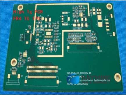
The glass transition temperature represents a fundamental thermal characteristic that defines the upper operational limit of PWB materials. Glass transition temperature, or Tg, is the temperature range in which a PCB substrate transitions from a glassy, rigid state to a softened, deformable state as polymer chains become more mobile.
Material selection based on glass transition temperature follows application-specific requirements:
- 130-150°C Range: Standard FR-4 materials suitable for consumer electronics and general-purpose applications
- 155-180°C Range: Enhanced materials for automotive and industrial applications requiring improved thermal stability
- 200°C and Above: High-performance materials for military, aerospace, and extreme environment applications
Polyimides with Tg of 250°C or above are suitable for the highest temperature systems. Designers consider Tg as a rough indicator for total Z-axis expansion and hence, a proxy for reliability indication for plated through holes.
Thermal Conductivity
Most PCB substrates have a thermal conductivity in the range of 0.3 to 0.6 W/M-ºC, which is quite low compared to copper, whose k is 386 W/M-ºC. This limitation presents challenges for thermal management in high-power applications.
As critical devices could fail at rates doubling for every 10°C increase of temperature, this pushes designers to use PWB materials with high thermal conductivity to remove heat directly from devices placed on the surface of the board. Advanced materials targeting thermal conductivity figures in the 1.0 to 3.0 W/m-K range, to achieve significant reduction in the board surface temperatures, especially near active devices.
For applications requiring superior thermal performance, ceramic materials are different in that their electrical conductivity is low enough for manufacturers to use them as PCB substrates, with aluminum nitride achieving thermal conductivity exceeding 170 W/mK.
Coefficient of Thermal Expansion (CTE)
Thermal expansion matching is crucial for maintaining reliability across temperature cycles. For the ideal PWB material, expansion in the Z-direction must match that of copper within the PTH to avoid damaging the plating inside the holes during thermal excursions in processes such as solder reflow.
The directional characteristics of CTE are particularly important:
- X-Y Axis CTE: 14-17 ppm/°C for PCB surface mounting applications
- Z-Axis CTE: 50-70 ppm/°C for through-hole reliability
Designers must match the expansion requirements of PWB materials to the expansion requirements of devices to be mounted on the surface, claddings, and the thermal planes buried in the interior.
Mechanical Properties: Structural Integrity and Durability
Flexural Strength
Mechanical strength requirements vary significantly based on application demands. The classification of materials by flexural strength provides guidance for appropriate selection:
- Standard Materials: 350-400 MPa strength for general purpose applications
- Reinforced Materials: 400-500 MPa strength for high-stress environments
- High-performance Materials: greater than 500 MPa for Military/Aerospace applications
Substrate Material Selection
The design substrate material used in PWBs is crucial for its performance and durability. Commonly used materials include phenolic paper, epoxy glass, and polyimide. Each material offers distinct advantages:
- Phenolic Paper: Cost-effective option providing moderate electrical insulation and mechanical strength
- Epoxy Glass: Enhanced electrical insulation and mechanical stability for demanding applications
- Polyimide: High-performance material with excellent thermal stability and chemical resistance for aerospace and military applications
Chemical and Environmental Resistance
Moisture Absorption
Moisture absorption affects the thermal and electrical properties of the substrate, as well as the ability of the material to resist conductive anode filament (CAF) formation when a PCB circuit is powered. Different materials exhibit varying susceptibility to moisture:
- FR-4 Epoxy: Absorption of only 0.15%
- PTFE (Teflon): Very low absorption of 0.01%
- Polyimide: Higher water absorption (0.4%)
Absorbed moisture can also vaporize on heating, as during soldering, and cause cracking and delamination, the same effect responsible for “popcorning” damage on wet packaging of electronic parts.
Chemical Resistance
Material resistance to processing chemicals and environmental exposure is essential for long-term reliability. Methylene chloride resistance is a measure of a material’s chemical resistance; specifically, the ability of a PCB material to resist methylene chloride absorption. Most materials achieve resistance values between 0.01% to 0.20%.
Manufacturing and Processing Considerations
Lead-Free Compatibility
PWB materials compatible with lead-free processes need to withstand higher soldering and reflow temperatures associated with lead-free solder systems—typically 30 to 50°C higher than traditional lead-tin systems. The requirements for lead-free compatible materials include:
- Glass Transition Temperature: Greater than 155°C
- Decomposition Temperature: Greater than 330°C for 5% decomposition
- Overall CTE: Less than 3.5%
Lamination Parameters
Lamination requirements include temperature ranges of 175-185°C, pressure of 250-400 PSI, and time periods of 45-90 minutes, with specific parameters dependent on material glass transition temperature, thickness, and layer count.
Cost Considerations and Material Selection
The economic impact of material selection extends beyond initial material costs. Material selection significantly impacts costs through both direct material expenses and processing requirements. High-performance materials can cost 3-6 times more than standard FR-4 and may require specialized processing parameters.
Material cost comparison reveals distinct tiers:
- FR-4: Base cost reference (1x)
- Modified FR-4: 1.5-2x base cost for enhanced performance
- High-speed Materials: 3-4x base cost for superior characteristics
- RF/Microwave Materials: 4-6x base cost for premium performance
Advanced Material Technologies and Future Trends
High-Frequency Specialized Materials
For demanding RF and microwave applications, specialized materials offer superior performance characteristics. Property tolerances include Dk tolerance of ±0.05 and other tightly controlled parameters essential for maintaining signal integrity at extreme frequencies.
Emerging Technologies
Current trends include the development of bio-based sustainable materials, integration of nanomaterials for enhanced properties, and smart materials with built-in monitoring capabilities. These innovations aim to address environmental concerns while improving performance.
Quality Assurance and Testing Standards
Comprehensive testing protocols ensure material compliance with performance specifications:
- Electrical Testing: IPC-TM-650 standards for dielectric constant and dissipation factor measurement
- Thermal Testing: ASTM D3850 standards for glass transition temperature and coefficient of thermal expansion
- Mechanical Testing: ASTM D790 standards for flexural strength evaluation
Conclusion
The selection of ideal PWB materials requires careful consideration of multiple interdependent factors including electrical properties, thermal characteristics, mechanical strength, chemical resistance, and manufacturing compatibility. The most critical factor depends on the application, but generally, the combination of electrical properties (Dk and Df) and thermal performance (Tg and CTE) are paramount. These properties directly impact signal integrity and reliability.
Rayming PCB’s comprehensive approach to material evaluation ensures that designers can make informed decisions based on specific application requirements while optimizing both performance and cost-effectiveness. As electronic systems continue to advance in complexity and operating demands, the importance of proper PWB material selection becomes increasingly critical for achieving reliable, high-performance electronic products.
The evolution toward more sustainable and advanced materials, including bio-based alternatives and nanomaterial-enhanced substrates, represents the future direction of PWB material technology, promising improved performance while addressing environmental considerations that are becoming increasingly important in modern electronics manufacturing.
Related posts:
- Panasonic Halogen-free MEGTRON6 R-5375 Laminate – An Ideal Material for Communications Infrastructure Equipment
- XC3S50A-4TQG144I is a Spartan-3A FPGA with 5 Functional Elements
- Elements Influencing SMT Soldering Quality and Improvement Measures
- Elements Ensuring Your First-Time Success in New Product Introduction (NPI) during Electronic Manufacturing


