
RAYPCB · ENGINEERING REFERENCE
Isola I-Tera MT40 PCB: stackup, fabrication & rfq
Turn construction data into a controlled multilayer build. Review dielectric thickness, timing sensitivity and the material evidence needed for a useful quotation.
Original engineering guidance · References checked September 28, 2026
What makes an I-Tera MT40 PCB a controlled build?
An Isola I-Tera MT40 PCB is a finished circuit board built with a specified I-Tera MT40 laminate and, where required, an approved prepreg construction. The material name alone does not define the board. Core thickness, pressed bondlines, glass style, copper foil, layer assignment and the electrical model must describe the same physical structure. This page focuses on turning that structure into a fabrication request, rather than treating the product data sheet as a ready-made stackup.
The practical buying question is not simply whether a supplier recognizes the grade. It is whether the proposed construction can be reviewed against your routing, thickness, hole and verification requirements. A quotation should identify the material being purchased, assumptions still open, and the records supplied with the finished boards. You can send a drawing for review before completing either worksheet below.
Read the material data with its measurement method
The official I-Tera MT40 product documentation identifies laminate and prepreg forms. Its typical table reports Tg as 215°C by DSC, 230°C by DMA and 210°C by TMA. These are method-dependent results, not three interchangeable temperature grades. The same table gives Dk 3.45 at 10 GHz using IPC-TM-650 2.5.5.5 and Df 0.0031 using Bereskin stripline. Typical values are reference data, not contractual limits for every construction.
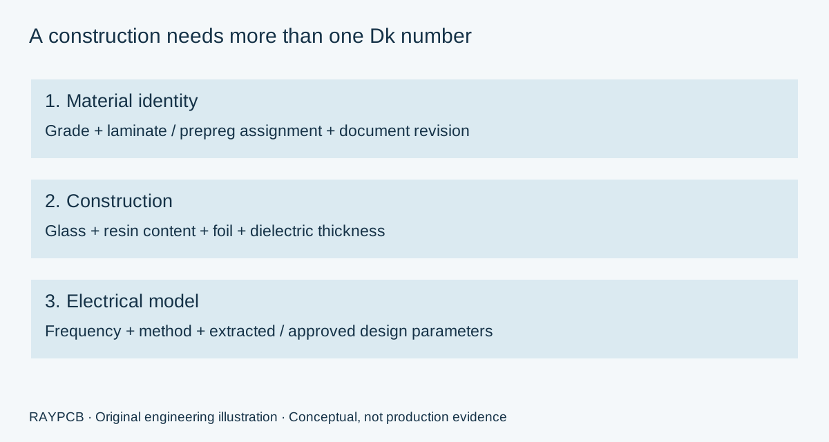
For a routed board, select the appropriate construction record and agree the solver input with the fabricator. A thinner dielectric may use a different glass and resin combination. A different foil can change conductor loss even when the resin system stays the same. Record the source revision alongside the values so a later engineering change does not silently substitute a newer table into an already qualified design.
| Record | What to keep | Why it matters |
|---|---|---|
| Material | Exact grade and laminate/prepreg assignment | A generic family name does not specify the complete build |
| Construction | Glass style, resin content, dielectric thickness | Geometry and effective electrical behavior depend on the construction |
| Copper | Foil identity, starting weight, finished requirement | Surface texture and plating affect the actual conductor |
| Electrical basis | Frequency, method and model version | Avoid mixing a test value with a different design assumption |
Start from finished geometry and work inward
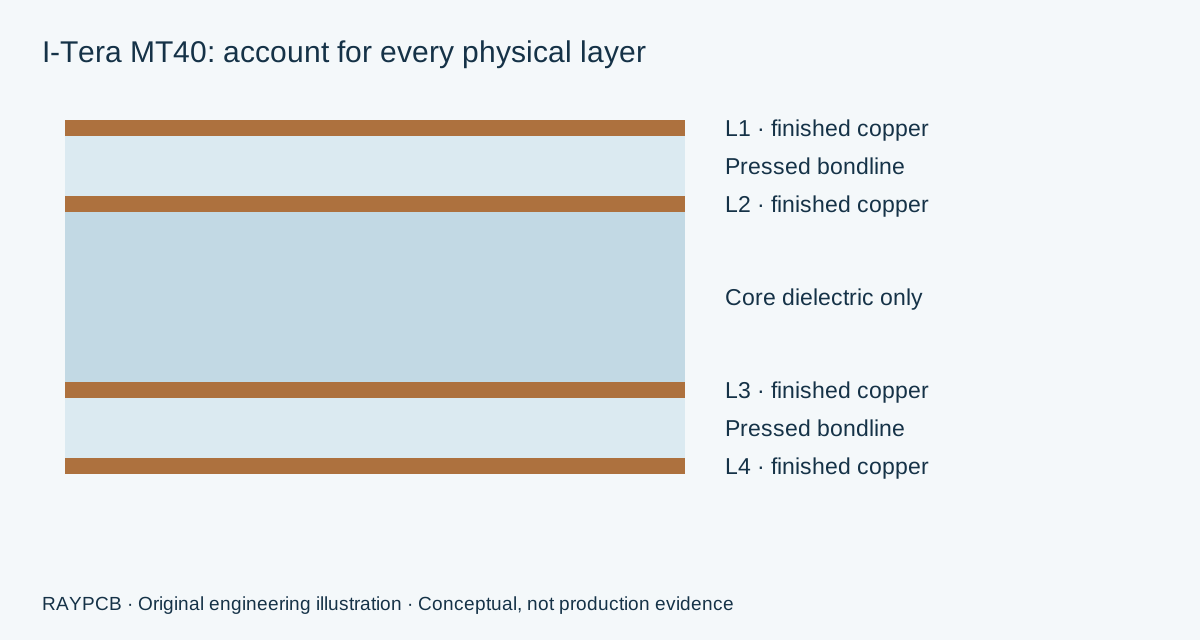
A useful stackup drawing names each copper layer and each dielectric interval. State whether core thickness includes copper; for the calculator here it must mean dielectric only. A prepreg entry means the complete pressed bondline, including all plies contributing to that interval. It is not the thickness of an unpressed sheet. This prevents the common mistake of adding the same core copper or bondline contribution twice.
For a four-layer concept, the outer signal layers may reference adjacent inner planes. That is only a starting topology. Plane splits, power assignment, stitching and component breakout decide whether the references are useful. The controlled impedance design guide addresses geometry and reference choices; the material worksheet does not replace its electrical review. An all-I-Tera construction and a hybrid construction also need separate process approval, even when their total thicknesses are equal.
Mechanical symmetry helps organize the proposal, but equal nominal thickness is not a prediction of flatness. Copper distribution, resin demand, panel shape and the thermal history can differ across a nominally symmetric stack. Show unusually heavy copper areas, cavities and local features early, so the quote is not based on a simplified stack that will later change.
Four-layer thickness planner
Use this worksheet when reconciling a proposed dielectric core with two complete pressed bondlines and four finished copper contributions. It deliberately keeps the construction small and inspectable. The inputs start blank. The example button provides arithmetic values only; no listed thickness is an approved I-Tera material offering. For another layer count, use the appropriate multilayer PCB planning route and retain the individual layer assignments.
RAYPCB ENGINEERING
High Performance MaterialsI-Tera MT40 four-layer thickness planner
Loading I-Tera MT40 four-layer thickness planner…
A 1.60 mm thickness account, not a press recipe
Suppose the dielectric-only core is 1.10 mm, each complete pressed bondline is 0.18 mm, and the four finished copper layers contribute 35 µm each. The accounted stack is 1.10 + 2 × 0.18 + 4 × 0.035 = 1.60 mm. If a reviewed drawing supplies a total worst-case allowance of ±0.10 mm, the entered interval becomes 1.50–1.70 mm. The tool does not invent that tolerance from the glass style.
If the finished-copper requirement changes to 50 µm per layer while everything else stays fixed, the account becomes 1.66 mm. Reducing a bondline to recover thickness can alter impedance, resin fill and available prepreg choices. Treat that adjustment as a stackup revision, rather than editing only the total on the drawing. Surface finish and coating dimensions are excluded from this example and need the same reference convention as the mechanical requirement.
From approved stack to representative evidence
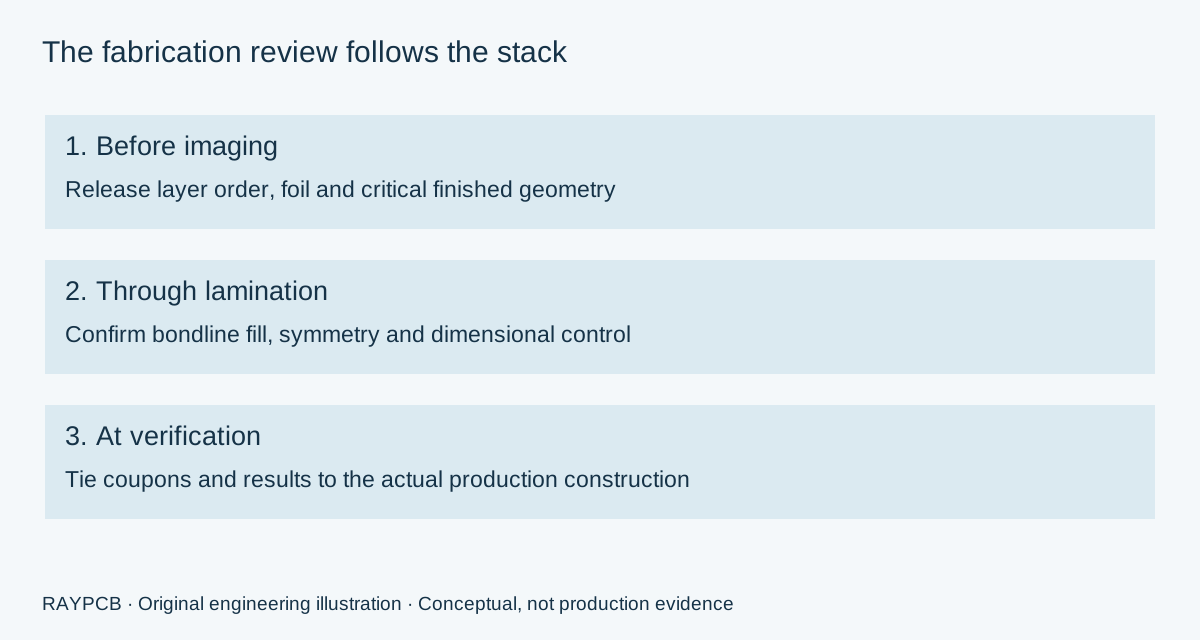
The I-Tera MT40 processing guide is a manufacturer starting reference, not a universal recipe for every press, panel and copper pattern. The fabrication review should connect material preparation, bondline filling, imaging compensation and hole preparation to the actual board. Copying a nominal process setting into an RFQ rarely answers the more useful question: which finished requirement does that setting help control?
Ask how the proposed construction will be represented in the verification plan. An impedance coupon should correspond to the relevant layer, dielectric, finished trace geometry and process. A generic coupon on a different interval may not answer the design question. Similarly, a continuity test checks connectivity, whereas an RF or high-speed characterization evaluates behavior over a specified measurement setup and frequency range. Define these as separate deliverables when both are required.
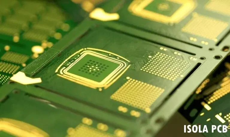
Drilling and plating deserve attention when board thickness, small holes and repeated thermal exposures interact. Specify the finished bore and tolerance separately from the fabricator's prepared drill. Identify hole spans and critical populations. Do not infer a plated-hole reliability claim from Tg, or a signal-integrity result from successful electrical continuity testing. A useful acceptance plan describes the feature, specimen, conditioning, method and the criterion agreed for the project.
Where the construction decisions become visible
A mixed-signal communications board may combine short RF paths with longer digital interconnects. The longest route is not automatically the hardest requirement: a launch discontinuity, an unreferenced transition or a dense breakout can dominate a smaller structure. Mark critical routes on the fabrication notes, identify the model used, and distinguish what must be held dimensionally from what may be adjusted after engineering review.
For a production transfer, retain the approved material record rather than sending only a board photograph and previous unit price. Ask the receiving supplier to list deviations in foil, core/prepreg assignment, tooling panel and measurement method. Review those differences before ordering a repeat build. The resulting decision is more useful than a broad claim that two boards use the same brand and therefore should behave identically.
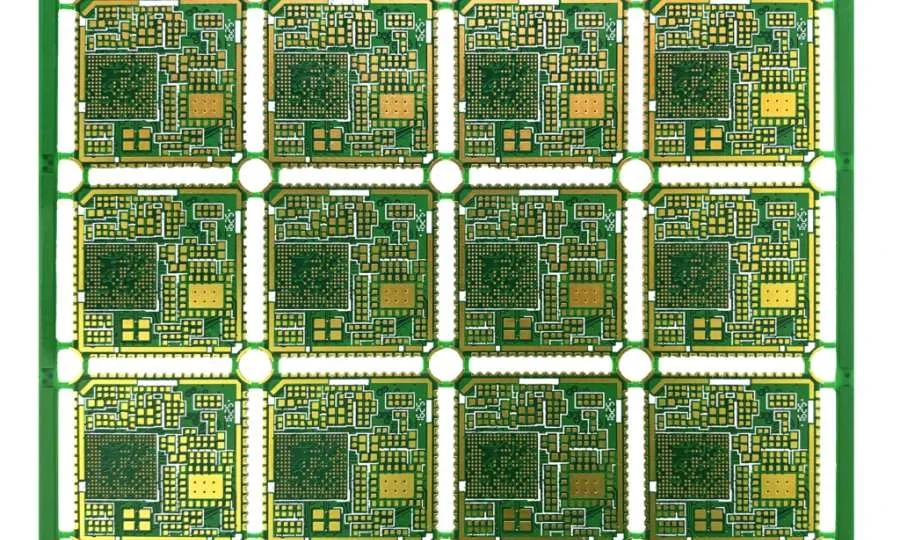
What changes the I-Tera MT40 PCB budget?
Panel utilization, exact material construction, foil choice, tooling, yield assumptions and verification scope affect the planning budget. A small quantity may still require a whole production panel. Coupons and tooling borders occupy space and can change the number of usable positions. The estimator uses that agreed position count; it does not nest your Gerber outline or check material stock.
Keep optional RF characterization separate from included fabrication inspection. Otherwise a comparison between two quotations can accidentally compare different services. An extra per-board allowance should include only work not already counted in the panel price. One-time engineering and verification belong at lot level. For a commercial route overview, see PCB Manufacturing; for other Isola systems, return to the Isola PCB material family.
RAYPCB ENGINEERING
High Performance MaterialsIsola I-Tera MT40 documented lot budget
Loading Isola I-Tera MT40 documented lot budget…
The displayed total is an uncalibrated planning estimate until you enter a documented quote basis. There is no built-in market price or assumed multiplier over FR-4. The result can be downloaded locally or placed in an email draft. Contact does not automatically receive the inputs or files. Attach the brief manually and include the original fabrication files when requesting a binding quotation.
Questions to resolve before ordering
Is the headline Dk the correct value for my microstrip?
Not automatically. Distinguish the measured bulk material value, construction-specific data and the effective permittivity of the modeled transmission line. Record the relevant frequency, test method, geometry and approved solver assumptions. A microstrip field occupies more than the substrate alone.
Can the fabricator change line widths to meet impedance?
Define the adjustment permission in the released requirements. The final proposal must remain compatible with spacing, breakout, copper and electrical constraints. Ask for the revised geometry and stackup to be reviewed before manufacture; do not leave an unlimited adjustment permission implied by a target impedance.
What should the quotation request include?
Send fabrication outputs, a dimensioned drawing, quantity, desired delivery date, exact material and foil requirements, stackup, impedance table and verification scope. Mark unresolved choices and permitted alternatives. Include the revision of every attachment so a response can refer to one coherent build.
Is a higher Tg sufficient reason to change laminate?
No. Thermal measurements, electrical requirements, copper adhesion, hole construction, moisture handling and process qualification address different concerns. Review the reason for changing material and the evidence needed to approve it. A single headline number cannot determine equivalence or service life.
Discuss the exact material and construction
Send the board revision, construction, quantity and the material, electrical or fabrication question you need reviewed. Identify unresolved requirements so the response can address them.
Send requirements for reviewOptional: attach the downloaded worksheet manually. This guidance does not certify a design, approve a shipment or replace the applicable authorized standards.

