All You Should Know About the Arduino Radar Project

Arduino Radar Project

Are you aware? During the Second World War, radar was created for the very first time as a technique for spotting hostile aircraft. Technology has advanced, and it is now utilized in a variety of industries. Radar technology has undergone major developments during the past few decades. In this article, we’ll create the Arduino radar project that uses an ultrasonic sensor to detect objects. Electronics is more controlled thanks to the Arduino microcontroller.

The goal of the Arduino radar project is to create a working prototype of the radar system that can detect both moving and stationary objects. The performance requirement for this radar system varies, and this is also offered in a range of sizes.

In this Arduino Radar Project, we’ll demonstrate how to use Arduino as well as Processing for creating a straightforward radar application. The Processing application is used to implement the Arduino radar project.

A long-range technology for object detection called radar employs radio waves in determining an item’s range, speed, as well as position. Aircraft, marine, missiles, ships, weather forecasting, and automobiles all employ radar technology.

Despite the fact that this project’s title implies Arduino radar Project, sonar technology is actually used since we will be employing the ultrasonic sensor in detecting the availability of any item within a specific range.

In What Ways Does Radar Function?

Arduino Radar board

Radio Detection as well as Ranging is what the term RADAR refers to. The object detection technique called radar employs microwaves to ascertain the speed, direction, altitude, and range of objects falling within a radius of 100 miles of the location.

Any item in its path will reflect the microwaves or radio waves that are transmitted by this radar antenna. This makes it simple for us to identify the object within the range of the radar. The fundamental operating principle is: The electromagnetic sensor called a radar is used to find and find objects.

The radar radiates microwaves or radio waves towards outer space. Reflecting objects block some of the waves. These radio waves that are intercepted, hits its target, as well as reflect off of it in numerous ways. Some of the waves could be redirected to the radar, which will then pick them up and amplify them.

If such waves are retransmitted at their source, it indicates that the object is moving in the direction of the waves. The most recent versions of radar systems are extremely sophisticated and have a wide range of uses, including air traffic management, radar astronomy, air defense, antimissile systems, and space surveillance, among many others.

What Does the Ultrasonic Sensor Offer?

FULL PCB MANUFACTURING Quote

The ultrasonic sensor can be described as the proximity sensor used to determine how close something is. It transmits ultrasonic waves to detect the object, and then it turns these reflected waves to electrical signal. The sound waves move more quickly than the sound we can hear.

The receiver and the transmitter are the two primary parts of it. After the sound has travelled from and to the target utilizing a piezoelectric form of crystal as the transmitter, it is heard by the receiver.

The sensor helps in measuring the amount of time that passes between the sound being transmitted by that transmitter and being reflected back toward the receiver in order to calculate the distance of the object. The formula to use for the calculation is:

D = 1/2 T x C

D is for distance, T is for time, and C is for the speed of the sound denoted by 343 meters per second.

The majority of such sensors are used in the auto self-parking as well as anti collision safety systems. This is employed in industrial technology, systems for robotic obstacle detecting, and many other fields. Consult the working principle of the ultrasonic sensor to learn more about this device.

What Does Servo Motor Mean?

A servo motor can be described as a straightforward DC motor which may rotate at a particular angle with the aid of supplementary servomechanism.

Only the amount of rotation we specify will cause this motor to halt. Positional feedback is used by the closed-loop servo motor to regulate position and speed. A servo motor, control circuit, shaft, potentiometer, amplifier, driving gears, as well as either a resolver or encoder are components of the closed-loop system.

This servo motor does not operate like a typical electric motor that begins and stops depending on the amount of power applied. The signal would cause the servo motor to operate.

Servo motors now are often employed in industrial and robotics applications. Additionally, they are frequently observed in DVD or CD players, RC automobiles, and RC planes. Servo motors are used in thousands of other applications in the daily lives of humans in addition to these.

Read the working principle of servo motor to learn more about it.

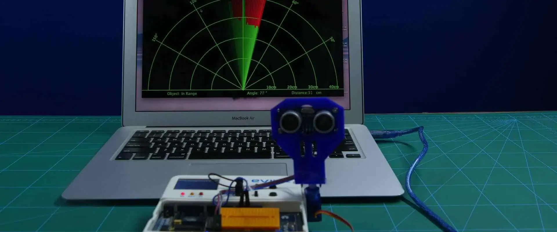
Arduino Radar Project Overview

Arduino Radar PCB

This Arduino Radar Project can majorly be described as a unique visual project rather than one that uses circuitry. Of course, you may make use of a variety of hardware, including the Arduino UNO, the HC-SR04 ultrasonic sensors, as well as the servo motor; however, the Processing application’s visual representation is what’s most important.

If you recall, one of our earlier Arduino Radar projects that utilized the MPU-6050 Sensor made use of a Processing Application. I advise you to check over your project before moving on; you are not required to actually execute it; just be aware of how it is done.

I utilized Arduino for reading the data out from MPU-6050 Sensor then deliver it to the Processing Application via the serial communication or COM Port for this MPU-6050 Project. A sketch for the Processing would modify the model aircraft’s orientation in response to the data received.

Using the same idea, I will use Arduino to gather data from this ultrasonic sensor and transfer it to the Processing, where a straightforward graphics program will be used to simulate a radar screen.

Getting the Fixture Ready

After connecting everything, I utilized a unique mounting bracket, for fixing of this ultrasonic sensor before building the fixture for this structure.

This mounting bracket then is secured to the servo motor using screws. Please firmly attach your servo motor to the surface using double sided tape, denoted as DST in order for it to support the bracket’s weight as well as that of the ultrasonic sensors.

The step is not required. You may also mount this ultrasonic sensor using the servo motor as well as a straightforward cardboard frame.

What are the Components Required for the Arduino Radar Project?

Below are the necessary components required for the Arduino Radar Project.

  • Arduino UNO
  • Hardware
  • Connecting wires
  • Servo Motor (TowerPro SG90)
  • Ultrasonic Sensor (HC-SR04)
  • Jumper Cables
  • Mounting Bracket (this is optional) โ€“ for the Ultrasonic Sensor
  • Power supply of 5V
  • USB Cable (this is meant for Arduino)
  • Circuit Design
  • Processing Application
  • Arduino IDE
  • Software

If you check the project’s circuit diagram, then you can see how basic the project’s circuit is designed. The ECHO and TRIG Pins of this Ultrasonic Sensor will be connected to the Pins 10 and 9 of the Arduino respectively, while the Servo’s Control Pin will be connected to the Pin 11 of your Arduino.

Hardware Connection

This connection of a Arduino radar project can be explained with a figure.  Connections are extremely straightforward. Here, the Arduino Uno has been used to connect a servo motor including an ultrasonic sensor.

You have to complete one crucial stage in the build or construction after connecting the connections (this is not mandatory though). I have utilized a mounting bracket because the ultrasonic sensor needs to sweep a 1800 arc (with assistance from the servo).

This mounting bracket gets fastened to a servo motor once the sensor has been fixed. Use the double-sided tape for securing the servo onto the surface securely because the bracket as well as Ultrasonic Sensor will add weight to your device.

The step is not mandatory, and you may hold this ultrasonic sensor tightly to the servo using a straightforward cardboard structure.

A Word about Processing

Processing can be described as a visual arts-based coding program for those who are just new to programming. Just visit the link then select your platform to download the app.

For 64-bit Windows computers, you can extract the zip file’s contents after downloading it to locate the .exe file processing application.

The following step is to utilize this URL to get a unique library referred to as “Toxi.” Extract all zip fileโ€™s contents of the “toxiclibs-complete-0020” to a folder with the same name after downloading it, then move this folder to your Libraries directory for processing.

Conclusion

This Arduino Radar Project can majorly be described as a unique visual project rather than one that uses circuitry. Radio Detection as well as Ranging is what the term RADAR refers to. The object detection technique called radar employs microwaves to ascertain the speed, direction, altitude, and range of objects falling within a radius of 100 miles of the location.

What is Copper Inlay PCB?

copper inlay pcb

All over the world, Copper Inlay PCB has been well known and is starting to be used more frequently for the Heat Dissipation PCBs. There are different businesses creating and distributing Copper Inlay PCBs.

The Copper Inlay PCB is widely utilized in a variety of industrial industries, particularly in automotive components that are crucial to public safety. Given the increased heat generation caused by parts with greater and more varied performance, the heat dissipation countermeasures are more crucial to preserve product performance as well as lifespan.

Additionally, natural dissipation of heat from the parts themselves is made challenging by the downsizing of parts. This PCB must be designed such that heat can be dispersed through its traces. By applying pressure, our “Copper Inlay PCB” can effectively dissipate heat through the pressing of copper to the circuit board under the components for heat generation.

What Does a Printed Circuit Board Mean?

PCB copper inlay

Copper conductors are used to make electrical connections in-between the components on a circuit board, which is the electronic assembly. Electronic components are mechanically supported by printed circuit boards, thereby allowing the device to become housed inside the enclosure. Also, the manufacturing process, the packaging of integrated circuit coupled with the bare circuit board’s structure must all be taken into consideration while designing the printed circuit board.

Copper traces, conductive planes, and pads are examples of conductive structures found on circuit boards. The insulating material is laminated in-between conductors layers to form this mechanical structure. The silkscreen material gets printed on the top of the non-conductive soldermask to create a legend for the electronic components, which is then plated as well as covered with solder mask.

The bare board is now transported into the circuit board assembly immediately the fabrication steps are completed so the components can be soldered onto the circuit board then this PCBA could be tested.

Within our electronics industry, the PCB design somehow has developed to a unique vertical. Circuit boards are crucial since they provide sturdy support for holding the components in place, electrical connections present between the components, as well as the small packaging which may be added in the final products.

Reliable software can assist in taking a design right from the concept to its manufacturing. The simplest possible circuit board needs careful design using specialist software programs. In this post, we’ll delve deeper into the definition of a circuit board, its design, as well as some of the significant factors that you have to comprehend during the design of circuit boards.

What Does Copper Inlay PCB Mean?

FULL PCB MANUFACTURING Quote

Heat from the heater elements positioned on the electronic circuit boards can be released via copper inlays and directed to the heat sink bottom side by the copper inlay PCB.

In the Metal Inlay Technology, there’s a large copper element which is pressed in the circuit board which is used to conduct heat away from the electronic components. Direct connections between this heat-emitting component and the metal inlay are possible. Typically, for this, the copper inlays used have 5mm as its minimum diameter as well as a thickness that falls between 0.8 and 2.5 mm. Depending on the size and shape, these metal inlays come either entirely or partially automated during insertion.

These metal inlays could be of any shape. Drilling or milling the circuit board creates the necessary recesses.

The initial drilling technique may generate mounting the holes to a 6.35 mm diameter, which is cost-effective. When compared to traditional thermal vias, the utilization of metal inlays significantly improves heat conductivity (via the circuit board).

Application of Copper Inlay PCBs

All over the world, Copper Inlay PCBs are well known and is starting to be used more frequently for the heat dissipation circuit board. The copper Inlay PCBs are utilized extensively across a variety of industrial sectors, and is particularly prevalent in automotive components that are crucial to public safety. Start-stop systems, ABS, ESP, and motor controls.

Additionally, Copper Inlay PCB is commonly employed in High Efficiency Humanoid Robots. Rectifier and inverter, control electronics, power electronics, power supply for the server, systems for battery management are examples of industrial electronics.

Lighting Technology: Specialty projectors, LED lighting, and movie technology are examples of lighting technology.

In order to preserve the performance and lifespan of a product, heat dissipation countermeasures become more crucial as a result of parts’ greater and more varied performance.

Additionally, natural dissipation of heat from the parts themselves is made challenging by the downsizing of parts. The PCB must be designed such that heat can be dispersed through its traces.

Benefits of Copper Inlay PCB

Copper-to-pcb-edge
  • Effective heat dissipation due to the component’s direct connection to metal inlays
  • Because multiple layer PCBs and the two sides of the part mounting board are an option, more flexible designs are available when compared to the aluminum base circuit board.
  • Miniaturization
  • Use of an affordable heat dissipation solution
  • Increasing the circuit efficiency through more flexible part placement
  • The reliability of the solder connecting parts will increase when compared to the Aluminum Base Circuit board because copper has a lower linear thermal expansion coefficient than aluminum.
  • The implementation of a cost-effective heat dissipation solution.
  • By removing the fastening screw method for heat-generating parts, lowering cost, and streamlining the assembly process, you can achieve requirements such as improved reliability.
  • Surface mount as well as lead portions can both use the same heat dissipation arrangement.
  • The ability to combine with different technologies, such as semiflex, heatsinks, etc.
  • Optimal conduction of heat across the circuit board: the uninterrupted copper path permits good conduction from its heat source to its heatsink.
  • These metal inlays can be electrically connected, even to its interior layers.
  • Complete freedom for choosing the metal inlays’ geometry

Conclusion

Before PCBs, components were usually packaged by mounting them to the rigid substrate and adding individual wires onto the components. Larger circuits might incorporate numerous electrical components with numerous wires, and conductive routes were created by soldering the metal components onto the wires.

Heat from the heater elements positioned on the electronic circuit boards can be released via copper inlays and directed to the heat sink by a copper inlay PCB.

What are the Responsibilities of an Electrical Hardware Engineer?

RFI Coating

Electrical engineers play significant roles across several industries. These engineers maintain power infrastructure, develop communications systems, and do a lot more.  Also, electrical hardware engineers face a lot of challenges in their career. However, with the right qualifications and skills, these problems can be tackled. In this article, we will discuss what electrical engineers can do and the qualifications needed to become one.

What does an Electrical Hardware Engineer do?

Electrical hardware engineer designs, develop, and test hardware components for computers and other electrical systems. The duties of this engineer include designing and developing hardware components, test data analysis, elimination of errors, and designing hardware for electrical appliances. The main responsibilities of an electrical hardware engineer are to create and design electric components, make new modifications, and carry out ongoing maintenance.

Electrical hardware engineers design devices that comprises processors  and some computer components. The duties of an electrical hardware engineer include monitoring the production process and partnering with software developers. Furthermore, this engineer works with digital and analog circuitry.

An electrical hardware engineer must be able to create a circuit design, collect and analyze data, prepare operational plans, create electrical schematics, and operate computer systems.

What is an Electrical Hardware?

Electrical hardware refers to material components included in electronic devices like televisions, computers, wearables, and more.  The hardware and the software are what makes a device to automatically carry out a series of tasks. Furthermore, the hardware refers to the physical part of the device. Therefore, one can say the hardware is the body of the device while the software is the soul.

When you dismantle a computer, you will see the interconnection between a set of electrical, electronic and mechanical components. Also, you will see how these components are assembled. This includes  graphic cards, cables, fans, chips, switches, and hard drives. The physical elements of a device that can be touched and seen is the hardware of the computer. More so, any electronic device connected to the computer as a mouse, keyboard, memory card, or a monitor comprises hardware inside.

What are the Responsibilities of Hardware Electrical Engineers?

Hardware electrical engineers donโ€™t just develop and test electrical components, they have other responsibilities aside that:

  • Enable the integration of the latest design procedures, techniques, and methods.
  • Ensure electronic lab operations, new processes, and incoming work are effectively managed.
  • Take control over test engineering on new strategies.
  • Offer support to a team to ensure hardware products through life cycle.
  • Consult with other electronic component suppliers and vendors to ensure compliance to product and project.
  • Direct equipment function and design to enable technical leadership for the development of all products.
  • Specify test methodology and carry out tests to verify the performance, reliability, and quality of a product.
  • Create validation procedures and write requirements for code to test prototype.
  • Detect and confirm any product risks and cooperate with team to prevent them.
  • Work with other  engineering contracts as needed.
  • Cooperate with cross functional teams in order to validate the functionality of electronics hardware components.
  • Figure out design data to offer support to team members and various clients.
  • Choose and evaluate personnel to be certain about the efficient operation of the group.
  • Carry out failure root cause analysis and integrate corrective actions to prevent it.
  • Get involved  in  reviews of critical design reviews and assessments of risks.
  • Develop and lead an autonomous vehicle validation team.
  • Ensure the team is led to develop and manage the system integration bench of the autonomous systems.
  • Implements and maintains procedure and policies to ensure growth and quality of department.
  • Complies with company and customer policies and standards.

Qualifications to Become an Electrical Hardware Engineer

FULL PCB MANUFACTURING Quote

There are certain qualifications you must have to become an electrical hardware engineer. This includes a bachelorโ€™s degree in electrical engineering or computer engineering. Also, you will need to train under a program approved by the Accreditation Board for Engineering and Technology.

Most times, employers prefer software design experience. Also, you should keep acquiring more knowledge and skills ย to keep you up to date on new technologies and electronics trends. Asides educational qualification, you need to acquire knowledge of the manufacturing and prototyping process, have a good time management skill, and analytical thinking skills.

What Qualities Should an Electrical Hardware Engineer Have?

Electrical hardware engineers should have certain qualities. Aside the educational qualifications, these qualities help them perform well in their field. These engineers have a thorough knowledge of mathematics and science to solve complex problems. Successful engineers require a solid foundation in building, maintaining, and analyzing electrical systems. Below are qualities of a good electrical hardware engineer:

Clear communication

Electrical hardware engineers can make impact in an organization by sharpening their communication skills. Also, they should be able to communicate their ideas in such a way that non-technical audiences and fellow professionals can understand. Clients must be able to understand the recommendations of an engineer in clear terms.

Creative problem-solving

Electrical hardware engineers are always faced with one challenge or the other. These engineers must be able to proffer inventive and creative solutions to tackle complex challenges. Also, it is crucial that these engineers prepare themselves ahead to keep up with the constant changes and development in technology. They should as well experiment with different approaches to solving problems. An electrical hardware engineer may face new problems with every project. The ability to solve these problems in a creative manner goes a long way.

Leadership

In the engineering field, a good leadership quality is a plus. Electrical hardware engineers will need to partner with multidisciplinary teams. Therefore, these engineers must be able to determine the demands of every project and optimize every stage of operations. The ability to lead a team to achieve its goal is important. Engineers are faced with several challenges, however, with a good leadership skill, things can be made easy.

Conclusion

The main responsibilities of an electrical hardware engineer are to create and design electric components, make new modifications, and carry out ongoing maintenance. Engineers are face with several challenges; however, these professionals are trained to tackle these challenges.

Exploring the World of Line-Following Robots

Line following robot

Robotics technology has come a long way in recent years, enabling machines to do tasks that were once thought impossible. As a result, robots have become an indispensable part of our lives, from industrial automation to domestic applications. One such application is line-following robots. A line-following robot is an autonomous robot that detects and follows a line drawn on the floor. It is also helpful in various applications, including industrial automation and guidance systems. The robot follows the line by adjusting its speed and direction according to the line. This article will provide an overview of the steps involved in building a basic line-following robot, the ways of controlling it, and its various applications.

An Introduction to Line the following robot

A line-following robot is an autonomous robot that detects and follows a line drawn on the floor. It helps in various applications, such as industrial automation, educational robotics, and entertainment. Additionally, Line following robots uses infrared sensors, ultrasonic sensors, or camera-based systems to detect and follow a line. The robot follows the line by adjusting its speed and direction accordingly.

Steps in Building a basic line following robot

line-following robots

1. Designing the Mechanical Part or the Body of the Robot

The first step in building a line-following robot is to design the robot’s mechanical part or body. The design should be such that it can move smoothly and with high accuracy. Additionally, the body should be lightweight and have a low center of gravity to ensure stability while moving. The body should also be able to handle vibrations and shocks when the robot encounters some obstacle. Finally, the body’s design should also enable it to take the load of the motor, sensors, and other components. For this purpose, a 3D-printed chassis is often helpful, which is strong and can take the load of all the components.

2. Defining the Kinematics of the Robots

The second step is to define the kinematics of the robot. The kinematics of the robot define its motion and helps to control its motion precisely. Engineers should design the kinematics of a line-following robot to move in a straight line with high accuracy. In addition, the kinematics should be able to handle turns and changes in speed. The most common kinematics applicable for line-following robots is a differential drive, which uses two motors and wheels to drive the robot.

3. Designing the Control of the Robot

The control system of a line-following robot should be able to track the line accurately and respond quickly to changes in the line. Therefore, the control system is usually designed using a PID or fuzzy logic controller. Moreover, the PID controller uses feedback from the sensors to adjust the speed of the motors and keep the robot on the line. Additionally, the fuzzy logic controller uses fuzzy rules to adjust the motors’ speed based on the sensors’ input.

4. Designing the Sensors.

The sensors for line following should be able to detect the line accurately and quickly. A line-following robot usually uses optical sensors such as infrared sensors or CCD cameras to detect the line. Additionally, the sensors should be able to detect changes in the line, such as turns and curves.

5. Integrating the Mechanical, Control, and Sensing Components

The fifth step is integrating the mechanical, control, and sensing components. The components’ integration should be done so that the robot can move smoothly and accurately. Engineers should wire the components together so the robot can receive input from the sensors and actuate the motors.

6. Programming the Robot to Follow the Line

The manufacturers should program the robot to follow the line accurately and respond to changes in the line. The programming should include algorithms to detect the line, adjust the speed of the motors, and handle changes such as turns and curves.

7. Testing the Robot

The last step is testing the robot to ensure it works as expected. Testing the robot should be done in various scenarios, such as straight lines, turns, curves, and obstacles. The testing should include different speeds and different surface conditions.

Ways of controlling a line following Robot

FULL PCB MANUFACTURING Quote
  1. Using Microcontrollers

The most common method of controlling a line-following robot is using a microcontroller.  A microcontroller is a simple computer that consists of a processor, memory, and input/output (I/O) ports. It is interconnected with the robot’s motors and sensors, and you can program it to analyze sensor data and direct the robot’s movement. This approach of line-following robot control is convenient and effective since it enables fine control over the robot’s motions. The microcontroller must be programmed, though; this takes a lot of knowledge and expertise.

  • Without the use of Microcontrollers

Alternatively, you can control a line-following robot without using a microcontroller. This method reuses simple electronic circuits to detect and follow the basic circuline-followingfollowing robot consisting of a photoresistor, light source, and motor driver circuit. The photoresistor detects the line, while the light source illuminates the line. Additionally, the motor driver circuit controls the robot’s motors. When the photoresistor detects the line, it sends a signal to the motor drive,r circuit, which then controls the robot’s motors to follow the line. The advantage of this method is that it is relatively simple and requires minimal knowledge and skill. However, it is less precise and efficient than the microcontroller method. Additionally, it is more prone to errors and requires frequent calibration and adjustment to ensure that the robot follows the line accurately.

Applications of Line Following Robot

  1. Industrial Applications

Line-following robots are increasingly helpful in industrial applications for automating processes that involve repetitive tasks. For example, they are applicable in welding, painting, and assembly processes, as well as in warehousing and logistics. Additionally, they can help in pick and place operations, where they can accurately and quickly pick up items from one place and move them to another.

  • In industrial applications

Line-following robots help to transport materials from one place to another, such as in the automotive assembly process. They help inspect the products and detect flaws, which can help in quality control and increase efficiency. They can also detect potentially hazardous environmental situations, such as a blocked pipe or a malfunctioning machine.

  • Automobile Applications

Line-following robots are helpful in automobile applications, such as autonomous driving. Autonomous vehicles use sensors and cameras to detect the environment and use line-following robots to stay in the correct lane and maintain a safe speed. Additionally, this technology can help reduce accidents and make driving safer.

  • Domestic Applications

Line-following robots help in various domestic applications, such as vacuum cleaners and robot mops. These robots use sensors to detect obstacles and stay on the right path, allowing them to clean more efficiently. Furthermore, they are increasingly applicable in lawnmowers and pool cleaners, helping to make these tasks more accessible and efficient.

  • Guidance Applications

Line-following robots are helpful for guidance applications, such as in museums and other tourist attractions. Manufacturers can program these robots to guide people around a particular area and provide information about the interests they are visiting. Additionally, they can help give directions to visitors and provide information about the area’s history.

Conclusion

In conclusion, line-following robots are increasingly becoming helpful in various applications, such as industrial automation, automobiles, domestic applications, and guidance applications. They use sensors to detect the line, and the robot’s speed and direction are modified accordingly. Additionally, line-following robots help automate repetitive tasks, provide guidance, and detect potentially hazardous situations. With their increasing popularity, the applications of line-following robots are expected to increase.

What Does Smart Agriculture Using IoT Entail?

Robotics in Farming

Connected devices somehow have successfully permeated every part of our lives as a result of the increasing adoption of IoT or Internet of Things. This increased adoption can be seen in smart cities, industrial IoT, home automation, fitness and health, logistics and automotive.

Therefore, it makes sense that IoT, linked devices, as well as automation will find use in agriculture, due to this, significantly improve almost every aspect of it. Furthermore, how could people still use plows and horses in an age where self-driving automobiles as well as virtual reality were commonplace rather than sci-fi fantasies?

What Does Smart Agriculture Mean?

The term “smart agriculture” is typically used to refer to the utilization of IoT technologies in agriculture. Then what does smart agriculture using IoT mean?

Farmers may use IoT sensors in gathering machine and environmental parameters, which will allow them to better manage anything from raising cattle to growing crops.

Farmers may determine the exact amount of fertilizers and pesticides they need to use in order to achieve maximum efficiency, for instance, by utilizing smart agriculture sensors in monitoring the condition of crops. The definition of “smart farming” holds true as well.

Integrating Smart Agriculture Using IoT

All IoT-based technologies are centered on data. Smart farms should establish a constant cycle which gathers as well as analyzes data in order to carry out the subsequent set of activities to assure optimization. An illustration of the smart farming process is as follows:

  • Observation: Sensing devices use sensors for sending the surroundings as well as collect vital information regarding the humidity, temperature, soil, etc.
  • Diagnostics: For any data analytics, sensor data is transferred to cloud systems based on the Internet of Things.
  • Making decisions: Farmers decide what to do depending on their analysis in order to produce better results.
  • Actions: The cycle restarts at the beginning whenever tasks are performed.

How Can IoT Help with Agricultural Issues?

Precision farming

A contemporary method of farming called precision farming uses precision values for producing and yielding more. It gathers precise information and numbers regarding agricultural lands. Because selections are done for each animal or plant instead of the entire product or herd of cattle, plants and animals receive the precise quantity of input they require.

Accurate Livestock Farming

Using precise processes that produce reliable data about specific cattle, PLF’s primary goal is to oversee, regulate, and regulate individual animals. Precision technology also helps in measuring and collecting data regarding animals every day, 24 hours a day. In the event that an issue arises with a farm animal, all farms are informed. As a result, the farmers can react rapidly to stop the spread of illness or all other obstacles.

Automation for smart greenhouses

The smart greenhouses have actuators and temperature sensors for control. These gadgets continuously gather and transmit data. This data is fed into clouds, which later store it on servers for use in the future. Following completion of a performance analysis, lighting control as well as spraying operations are managed appropriately.

Agricultural drones

Drones are used by farmers to gather insight and real-time data about the animals and crops in the barns. Drones fly overhead and keep an eye on the whole field, alerting farmers to any unusual activity. The drones are positioned for security reasons as well.

Climatic conditions are well monitored

The weather stations that incorporate numerous sensors for smart farming are arguably the most well-liked smart agricultural technology. They are spread out around the area and gather various environmental data before sending it to cloud. The measurements offered can be utilized in mapping the climatic conditions, select the suitable crops, and implement the necessary improvements.

Management of crops

Crop management tools are an additional IoT product category in agriculture as well as a component of precision farming. They must be set up in the fields to gather information pertaining to growing crops, such as precipitation and temperature as well as leaf water capacity and general crop health, just as weather stations.

So you can successfully stop any diseases and pests that could reduce your crop’s output, you can keep an eye on your crop’s growth as well as any irregularities.

Factors to Take into Account When Creating a Smart Farming Solution

FULL PCB MANUFACTURING Quote

We can see that there are countless applications for IoT use in agriculture. The performance and income of your farm can be improved in a variety of ways with the aid of smart technologies. However, creating IoT applications for agriculture is not a simple operation.

There are some difficulties you should take note of when planning to invest in smart farming.

Hardware

You must decide which sensors to use for the device if you want to design IoT solution to aid agriculture. Your decision will be based on the data you wish to gather and the overall goal of the solution.

In any event, your product’s success would depend on precision and dependability of the data that is acquired, thus your sensors’ quality is essential.

The brain

Each smart agriculture solution should be built around data analytics. If you are unable to comprehend of the obtained data, it won’t be of use in and of itself.

Therefore, to acquire meaningful insights from your data, you must possess strong capabilities for data analytics and employ predictive algorithms as well as machine learning.

Maintenance

For IoT solutions in agriculture, the difficulty of hardware maintenance is crucial because these sensors are frequently utilized in this field as well as are easily broken.

Therefore, you must ensure that the hardware is robust and simple to maintain.

Mobility

Applications for smart farming should be made specifically for utilization in fields. A farm manager or business owner ought to have on-site or remote access to the data using a desktop computer or smartphone.

Conclusion

Over the past few decades, farming has experienced some technological changes that have made it more industrialized as well as technology-driven. Farmers have improved control over the livestock production process as well as growing crops by using a variety of smart agriculture tools, making it more predictable as well as improving the efficiency.

How Smart Manufacturing IoT is Driving Industry Revolution

Smart Manufacturing IoT

Millions of wireless IoT modules utilized on factory floors, along with other cutting-edge technologies and procedures, have given rise to smart manufacturing.

IDC forecasts that in 2019, the manufacturing industry spent about $200 billion on IoT, more than twice more than the consumer industry, which was the second-largest when it comes to IoT vertical markets. Per a message from ISG on 4th June 2020, the industry of smart manufacturing had significant growth during Q1 2020, with a compound annual rate of growth of 12.4% predicted until 2025. How come?

Smart manufacturing IoT, also referred to as Industrial IoT or Industry 4.0, offers complete visibility of processes, assets, resources, as well as products in global markets that are intensely competitive. The outcome?

Optimized efficiency, enhanced ROI, and streamlined business processes are all supported by smart manufacturing. Our Company has aided clients in Connecting, Securing, and Monetizing their business operations with IoT technologies for some time now.

We provide some of industry’s best practices that has been compiled in our web dossier to assist businesses in making a wise transition towards “Industry 4.0.” Connection of equipment, integrating various industrial data, protecting industrial systems during the duration of your machine, and maybe licensing the intellectual property of your company are all essential to success.

Let’s begin immediately.

Smart Manufacturing IoT: How does smart manufacturing relate to the Internet of Things?

Manufacturing IoT

Factory managers may automatically gather and evaluate data using smart manufacturing to make better decisions and maximize production.

IoT connectivity systems installed at factory level transmit data from machines and sensors to the cloud. The data is examined, merged with relevant information, then disseminated to relevant parties with authorization.

This data flow is made possible by IoT technology, which uses both wireless and wired communication. It also allows you to track as well as manage processes offsite and instantly alter production schedules in real-time as needed.

And there’s more. It significantly enhances manufacturing efficiency, lowering waste, accelerating production, and enhancing yield and product quality.

Furthermore, there are numerous advantages to replacing this hierarchical structureโ€”which historically constituted a “shop floor”โ€” having an open, flatter, completely networked approach that integrates R&D and supply chain management.

Among them is the improvement of world manufacturing techniques linked to resource management cost, quality, and performance. It also makes it possible for the manufactured goods to actively participate in the planning and design of the manufacturing process.

Why? Since connected smart devices may send information to a factory, any quality problems can be found early on and rectified by changing the manufacturing methods or the product design.

It’s also excellent for getting consumer feedback. The trick? Additionally, smart gadgets can reveal information about how people utilize them. Also, it’s a great chance to modify features that better suit the market’s actual needs.

What Changes are being Made in the Manufacturing Market?

FULL PCB MANUFACTURING Quote

Powered by IoT, the Fourth Industrial Revolution has been profoundly changing the manufacturing industry (also known as factory 4.0). Technological advances have made it possible for this section to change through technological breakthroughs happening at an unknown pace.

Decision-makers today are being forced to rethink how the products are created and produced, much as how a steam engine brought about profound changes during 17th century as well as how the digital revolution shook the world during the later part of 20th century.

Machine Learning and artificial intelligence, industrial robotics, IoT analytics, 5G, as well as digital twins are other important enablers in addition to the Internet of Things.

What are the Implications of 5G for Smart manufacturing?

Higher bandwidth, lower latency, and faster speeds are all features of 5G. A nearly immediate remote reprogramming will enable this very same machine to carry out many jobs.

Additionally, it only takes a few seconds to remotely update robots on production lines. Robots will immediately provide haptic feedback to human operators who are remotely supervising operations, allowing them to actually feel whatever they will be doing in real time.

AI and machine learning will advance to previously unheard-of levels thanks to real-time communication. Smart manufacturing strategies to increase the development of corporate value. The IoT revolution has been predicted to have a significant positive impact on value and productivity.

To support their manufacturing industries, the three largest manufacturers in the worldโ€”China, the US, as well as Europeโ€”have started specific smart factory programs. In essence, these industry titans are involved in a battle for competitiveness in smart manufacturing.

The fourth industrial revolution as well as the Internet of Things is expected to benefit all forms of industry. Just consider it. Take for example, discrete manufacturing can be described as the process of creating unique things that can each be touched as well as counted separately and is frequently related to assembly lines. It includes increasingly connected objects like furniture, vehicles, and airplanes.

Similar to this, the IoT revolution benefits process manufacturing, which produces things in large quantities using well developed recipes, by improving plant monitoring, streamlining the supply chain, including enhancing the quality of the trace and track and processes for distribution.

Demand and supply will be balanced, product design will be enhanced, manufacturing efficiency will be optimized, and waste will be drastically reduced thanks to smart procedures.

Why is Security such a Big Deal During Smart Manufacturing IoT?

Currently, the manufacturing industry accounts for a third of all the attacks, making it the main infrastructure cybercrime victim. This is due to the fact that most traditional manufacturing facilities were not created considering cybersecurity and that hacking technology somehow has advanced significantly.

New risks appear as firms switch from conventional factories to the IP-based, IoT-connected systems. An increase in cyberattack surface is a natural result of integrating processes and other smart manufacturing components.

Cybercrimes and attacks that can result in remote access, interference, intellectual property theft, and data alteration or loss increase with each connection point. Many tried as well as true security measures still work, but they aren’t often included into systems right from the start.

Manufacturers should adapt by adding defenses to old, connected systems and equipment in order to guarantee acceptable security. And for brand-new, cutting-edge manufacturing facilities, security architecture must be taken into account from the start.

Is that terrible news? The adoption of organizational changes, fresh IoT technologies, as well as business models which might optimize operations, increase competitiveness, and provide clients with new services have also been slowed down by security concerns.

Sadly, businesses that lag behind will have a harder time keeping up the more progressive competitors who approach the problem head-on.

Setting Up a Smart Factory

The obstacles to unlocking exponential value are the construction and scaling of smart factories. Manufacturers must collaborate with factory automation vendors as well as systems integrators which offer solutions to update factories or create brand-new systems in order to remain competitive.

The best way for manufacturers in connecting as well as securing their systems for smart manufacturing IoT is through working with seasoned developers, integrators, as well as technology partners. The guidance required to design the optimal system to suit business needs can be obtained from seasoned partners.

Connect

Hardwiring, Bluetooth, WiFi, RFID, Wide-Area Networks of low power like LTE M and LoRa, including IoT Terminals which function right from the beginning and connect through industrial interfaces that are flexible are just a few examples of how manufacturing processes could be connected.

Each choice has particular advantages and best-case scenarios. Choosing a smart manufacturing IoT system will help in deciding the right solution that works best for personal use cases and can be assisted by a partner with relevant knowledge.

Secure

Reputable automation partners understand that security architecture is an important concern for manufacturing and a means of gaining a competitive edge in the market, so they incorporate it throughout a value chain. They also must think about security as well as how to safeguard intelligent manufacturing systems against errors or fraud.

The TKM technology enables manufacturers to divorce these qualifications from the manufacturing process, allowing for business scalability and maintaining customer trust.

Monetize

Successful monetization of a software can be described as another factor for industry participants to take into account. One of the most important steps in the production of industrial equipment is licensing and protection of intellectual property. This includes trade secrets, highly advanced software, and pricing schemes based on feature sets that change depending on usage.

What Actions should Stakeholders take to Safeguard the Smart Manufacturing IoT Facilities?

IoT Sensors

Every manufacturing systems must incorporate security measures from the beginning in order to enable failsafe production as well as provide protection from online threats. I’m sorry, but there isn’t a one-size-fits-all answer to this.

To defend and safeguard the hardware, the data, the network, as well as the software and applications that power smart manufacturing IoT systems, manufacturers must instead collaborate with experts.

Conclusion

5G serves as a catalyst that ensures new transformation to the industry and was created to meet the requirements of the industrial IoT. The revolution of industry 4.0 is set to be accelerated by 5G technologies by enabling even more flexibility, agility, quality, and cost control. This is why smart manufacturing IoT is very important.

What is the Significance of Visual Components Assembly?

Visual Components Assembly

Visual components assembly has what you need, whether you’re searching for a software to swiftly build and offer manufacturing solutions and perhaps a platform that will help you run any offline programming programs. View the products in the visual components assembly family that simulate 3D manufacturing.

What Does Visual Component Mean?

Numerous intelligent models are available from Visual Components, including 3D model databases, conveyors, and industrial robots. Models with vast dimensions and intricate shapes can be imported. The entire plant can be swiftly planned or designed by engineers. Engineers can analyze and validate their factories in a virtual environment.

The Visual Components’ “plug and play” feature is quite helpful. Allow engineers to complete a project swiftly and easily. Engineers can employ it to simulate robotic or logistical systems. It’s a crucial tool for automating planning and process.

PLC simulation is another feature that is integrated into Visual Components, and it may be done with a genuine robot or PLC. In order to attain the world of virtual actual integration, Visual Components even has offline PLC or robot program compilation.

What Services do Visual Components Provide?

SMT Visual Components Assembly

Smarter Simulation

This special platform of Visual components assembly was developed to support sophisticated simulation applications for 3D manufacturing. The PhysX engine, which powers its physics behavior, enables you to visualize and simulate functionality that is impacted by some physical forces like gravity, collisions, as well as material characteristics.

Greater Efficiency

The environment of the 64-bit Windows was intended to be fully utilized when Visual Components came to be. Better graphics, quicker loading times, as well as an overall improved user experience result from this. Large layouts are flexible to navigate. To enhance simulation performance, the memory management gets constantly enhanced.

Geometries may be swiftly imported into the 3D environment of Visual Components, thanks to the CAD converter’s optimization.

Streamlined UI/UX

Because Visual Components uses the well-known ribbon interface, commands are organized efficiently and new capabilities are simple to find. There is always access to 3D navigation, enabling greater flexible zooming, layouts rotation and panning. In order to help you save time during layout configuration as well as component design, Visual Components Assembly are constantly enhancing and optimizing user procedures and workflows.

Open Architecture

This Visual Components Assembly platform may be easily customized thanks to its modular and open nature. Because Visual Components is based on the.NET framework, many developers are already familiar with it. Additionally, we offer a Python API that is integrated into all the components of the Visual Components Assembly.

Advanced Rendering

You can examine more features and details with the help of Visual Components’ various rendering modes, which also make for a richer as well as a better viewing experience. Models inside the 3d environment look realistic thanks to sophisticated shading and lighting models, as well as the capability to examine material textures, and images and movies exported out from the program are of a professional caliber. When building new components, setting up layouts, and examining collisions, its x-ray mode aids in locating the reasons and problems at the root of the problem.

Visual Components can be described as a leading provider of solutions and software for the simulation of 3D manufacturing. ย When the company was first established by a group of simulation specialists, their modest mission was to make factory design plus simulation technology simple to use and affordable for manufacturing firms of all sizes.

Main Characteristics of Visual Components Assembly

FULL PCB MANUFACTURING Quote

Configuring the layout

This is Visual Components Assembly’s main program. Drag components from its eCatalog into its 3D environment to quickly construct layouts, then use the plug-and-play function to join suitable components.

Modify pre-defined parameters of the component, such as sizes, speeds, and colors, using the editing function of the properties. You can also utilize their library of components, which includes over 1,400 pre-built conveyors, industrial robots, as well as other parts from more than 40 leading industrial automation brands.

Process Modeling and Simulation

A straightforward yet effective method for controlling how production moves through your layout. Programming is no longer necessary for many modeling jobs because visual workflows may be done instead. Action panels that help in defining, amending, as well as managing processes, products, as well as the flow of production are included in the PROCESS tab.

The ability to observe and control production flow in the 3D environment also makes it simpler to assess, troubleshoot, and adjust layouts.

CAD Compatibility

Directly import any CAD files to the 3D environment. It is simple to integrate geometry files made using well-known software programs like Dassault, Autodesk, Siemens, PTC, as well as other CAD vendors thanks to Visual Components Essentials’ support for CAD file types gotten from many top CAD manufacturers.

Due of our compatibility with the most popular CAD formats, it is possible to import the geometry files natively the same way in which their design was made. Also, included in Essentials is the CAD import. Therefore, there’s no additional cost as well as plug-ins.

eCatalog

Benefit from their vast component library. This Visual Components eCatalog has a substantial library of different virtual models of equipment, machines, and robots from top manufacturers in the industrial automation, with more than 2,300 pre-defined components.

Project Deliverables

The files as well as deliverables you could generate have been improved, new templates have been made, and the procedures have been greatly streamlined. Screenshots from its 3D environment can be easily exported and included into the presentations.  

4K HD footage can be captured and exported. Create animated as well as interactive 3D Files that include simulations, bill of material, built-in navigation, as well as playback options. With this new 2D template for drawing, you can quickly convert 3D blueprints into 2D drawings that are perfect for presentations.

Reporting and statistics

Use line, bar, area, or pie chart to visualize the simulation statistics. A specialized statistics dashboard is used to generate, edit, and display charts. Users can visualize various dynamics of the production line using the dashboard, find bottlenecks, and assess changes in production performance.

Simulated data could be simply exported in Microsoft Excel or PDF data formats for additional in-depth study.

Conclusion

Visual Components Assembly comes with great features and you will surely enjoy these services.

Getting the Best Out of AC vs DC Power

AC Circuit Vs DC Circuit

Direct Current (DC) and Alternating Current (AC) are two different forms of electricityย applicable in various areas of everyday life. DC is a constant voltage that flows in one direction and mainly helps in battery-powered applications and medical devices. AC is an alternating current that flips direction and is common in transportation, industry, and communication. Although they have similarities such as current, voltage, power, resistance, frequency, and safety, they also have distinct features such as their definition, long-distance transmission, the flow of electrons, and graphical representation. With technological advancement, electricity has become an essential part of modern life. Direct Current and Alternating Current are the two forms of electricity that help power various applications. This article provides an insight into DC and AC, their similarities, differences, and advantages over each other, enabling readers better to understand the different forms of electricity and their applications.

DC Definition

The Low Cost PCB Assembly of Turnkey PCB Manufacturer

Direct current (DC) is an electrical current with a constant voltage and only flows in one direction. Some sources of this kind of energy include batteries, solar power, generators, and rectifiers. Modern gadgets like laptops, cell phones, and audio equipment use DC power. Since DC power can deliver a constant and reliable power supply, it is also highly applicable in motors. DC power is also helpful in communication systems to transmit signals between two sites. Since DC power is a dependable energy source, it applies to electrical systems and power grids. Rectifiers and converters often help us convert AC power to DC power, allowing for a wide range of applications.

AC Definition

Alternating current (AC power) is a form of electrical energy in which the voltage and current flow alternate in a wave-like pattern. Using a three-phase system consisting of a live conductor, a neutral conductor, and a ground wire, it is easy to send it to a consumer in its most basic form after producing it using a power source such as a generator, transformer, or rectifier. Next, it is applicable in powering things like motors, lights, and appliances. Because it is simpler to regulate and can be effectively transportable over greater distances, power suppliers prefer AC power over DC power.

Applications of DC

FULL PCB MANUFACTURING Quote
  1. Applications in medicine:

Pacemakers, defibrillators, and electrocardiographs all employ DC voltage. Furthermore, DC electricity also helps power the internal components of numerous medical devices, including hearing aids.

  • Communication:

Radios, telephones, and televisions are a few communication devices powered by DC electricity. In addition, both radio wave transmitters and receivers run on DC power.

  • Aviation:

Most aircraft systems, including the autopilot and navigation systems, depend on DC energy. Additionally, some aircraft use DC electricity to charge their batteries.

  • Space Exploration:

Different components of spacecraft, such as communication and navigation systems, and applications for space exploration, such as satellites and space probes, operate on DC voltage.

  • Lighting:

DC voltage is commonly applicable when powering lighting systems, such as those in street lamps. LED, halogen, and CFL bulbs all operate on DC electricity. 

To regulate the movement of the robotic arms, robotic applications frequently use DC motors, generators, and other equipment. The robot’s sensors and other parts all operate on direct current.

  • Transportation:

The motors in electric trains and trams typically depend on DC voltage. DC voltage is also applicable in many boats and ships to power their batteries and other electronic devices.

  • Applications in Industry:

Various industrial uses include cutting, welding, and process control systems. The manufacturing of steel and aluminum also employs DC voltage.

Applications of AC

RF Amplifier Manufacturer

Alternating current (AC) is the most widely utilized current in the world and is primarily applicable in industrial generation and transport. AC is a more efficient direct current (DC) because it has a lower risk of fire ignition, is more cost-effective, and can convert high and low currents to low and high currents using transformers. Furthermore, AC helps electric power motors convert electric to mechanical energy. This capability makes AC ideal for powering household appliances such as garbage disposals, dishwashers, refrigerators, and toaster ovens. Everyday items powered by DC include modern televisions (with an adapter transforming DC power from AC power), cell phones, torches, and electric autos.

In addition to powering electric motors and battery-powered applications, AC is also applicable in distribution of power. Transformers easily convert AC to other different voltages, which is impossible with DC. This aspect helps minimize losses when electricity transmission occurs at very high voltages. For example, if a source of 250 volts has a 4 amps current and cable resistance of one resulting in 1000 watts power transmission. Power loss becomes I2 x R, which is 16 watts. This example illustrates the importance of AC in power distribution and why it is the most popular current in the world.

Similarities between DC and AC

Ac and DC have the following features in common:

  1. Current: The movement of electrical current occurs in alternating current (AC) and direct current (DC). While AC is the alternating current that occasionally flips direction, DC is a steady current that runs in a single direction.
  2. Voltage: In an electrical circuit, voltage measures the potential energy difference between two points. While AC voltage fluctuates with the alternating current frequency, DC voltage is a constant voltage that does not change.
  3. Power: Power is a measure of the movement of electrical energy from one location to another and is a component of both AC and DC. Watts are the units for measuring electrical power in all systems.
  4. Resistance: This aspect measures the opposition to the passage of electrons, which is present in both AC and DC circuits. Ohms are the unit of measurement for resistance in both DC and AC circuits.
  5. Frequency: The frequency of an alternating current is the quantity of direction changes it undergoes per second. Contrary to DC systems, AC systems often have greater frequencies. Because of their increased ability to handle the electrical load, AC circuits,
  6. Safety: Safety is vital for both AC and DC circuits. Using fuses and circuit breakers is essential to prevent electrical overloads and short circuits. In addition, any exposed wiring needs proper insulation to avoid electric shock.

Differences between AC and DC

SMD Capacitor

The following are some of the main differences between Direct Current and alternating current:

1. Definition

AC stands for alternating current and is the type of electric current that varies instantaneously with time. The flow of electrons in an AC is bi-directional, meaning that electrons change direction periodically. On the other hand, DC stands for direct current and is the type of electric current that remains constant with time. The flow of electrons in a DC is unidirectional, meaning that the flow of electrons is in one direction only.

2. Long Distance Transmission

AC is more suitable for long-distance transmission as power losses are minimal due to the low resistance of AC transmission lines. This action is because of the common skin effect of AC transmission lines. On the other hand, DC is unsuitable for long-distance transmission as power loss is directly proportional to distance due to the high resistance of DC transmission lines. Again, this inefficiency is because of the high skin effect of DC transmission lines.

3. Flow of Electrons

In AC, the flow of electrons is bi-directional, meaning that electrons change direction periodically. This flow is due to the changing polarity of the AC voltage. On the other hand, in DC, the flow of electrons is unidirectional, meaning that the flow of electrons is in one direction only. Again, this directionality happens because of the constant polarity of the DC voltage.

4. Frequency

The frequency of AC varies between 50 Hz to 60 Hz, with different frequencies in different countries. On the other hand, the frequency of DC is zero, as the voltage and current remain constant.

5. Power Factor

The power factor of AC lies between 0 and 1, depending on the type of load. On the other hand, the power factor of DC is always 1, as the voltage and current remain constant.

6. Graphical Representation

The graphical representation of AC is a sinusoidal wave, with the amplitude and frequency varying depending on the type of load. On the other hand, the visual representation of DC is a continuous line, with the voltage and current remaining constant.

7. Generation Mechanism

Generating AC involves placing a current-carrying coil in a rotating magnetic field. As a result, the current generated will vary with the rotation speed. On the other hand, developing DC involves placing a current-carrying coil in a steady magnetic field. As a result, the current generated will remain constant.

8. Generating Devices

Alternators generate AC, while cells or batteries, on the other hand, generate DC.

9. Type of Load

AC is useable with resistive, inductive, or capacitive loads. On the other hand, DC can only be useable with resistive loads.

10. Capacitive Impedance

Capacitive impedance is low in AC as the capacitor allows AC to pass through it. On the other hand, capacitive impedance is infinite in DC as the capacitor blocks DC.

11. Applications

AC applies to high-voltage applications such as home appliances, office equipment, etc. On the other hand, DC is only applicable in low-voltage applications in electronic circuits.

Advantages of AC over DC

Automated PCB Manufacturing

The following are some of the merits of AC compared to DC:

  • First, the AC can transport more power over a shorter distance compared to DC. This capability is because, unlike DC, which flows in a straight line, power moves in a waveform, which is significantly easier to carry.
  • Since it won’t cause electric shock when appropriately handled, AC has more robust safety standards than DC. This aspect is because AC does not have a constant flow of current; instead, it runs in waves.
  • The AC eliminates the possibility of overloading or damaging the system by connecting several appliances to the same supply. This connectivity helps quickly achieve the desired voltage and current with the AC.
  • It is also easy to transform AC into several different forms, such as DC or other types of AC, which are helpful in many applications. This ease results from the AC’s easy adjustment possibility of utilizing transformers.
  • Due to the ease of measuring current and voltage, and the waveform of the AC, it is easier to monitor and control the AC than DC.
  • Due to its simplicity in regulation and adjustment to the correct voltage and current, AC is also more dependable than DC. This aspect is because, using transformers, the AC may be easy to adjust.
  • Since the AC can move across a broad region, it can quickly spread out over great distances. This results from the ease with which step-up transformers can transport AC over extensive distances.
  • Due to its simplicity of conversion into different forms, such as DC or other types of AC, AC is applicable in a wide range of fields. This versatility is a result of transformers’ simple ability to alter AC.

Advantages of AC over DC

Utilizing DC instead of AC comes with the following benefits:

Direct current systems are significantly more energy-efficient than alternating current power, with more powerful and efficient motors and appliances to provide unique features. For example, LED or DC-based lighting is about 70% more energy-efficient than its incandescent counterpart. In addition, recent advancements in the technology around the DC converter have enabled even greater energy efficiency when transferring electricity over long distances.

DC is also more compatible with the clean energy sources like solar and wind, as these sources donโ€™t generate power consistently and require energy storage solutions to deliver reliable energy. Solar photovoltaic systems produce DC energy, and batteries also store DC energy, making them the more suitable option.

Integrating energy sources increases with DC energy, as most energy storage methods are DC-based. This feature can lead to improved efficiency and reduced operating losses.

Electronic devices also function using DC power, losing 8-22% on converting AC power to DC. With the rising demand for the electronic devices, eliminating conversion losses from AC to DC is becoming increasingly important. It will lead to a shift towards DC power, prompting the development of advanced energy conversion technologies.

Finally, there is development of DC systems & hybrid AC/DC micro-arrangements to improve energy efficiency. Micro-grid systems help in combining local power production with primary grid to provide efficient energy, increased reliability even during disruptions, and opportunities for trading energy to lessen consumer costs.

DC technology is increasingly advancing, allowing it to benefit data centers, homes, and communities. It is already suiting many places AC power does not reach, such as rural China & India. Some Indiaโ€™s four regions are even testing out the direct supply of DC energy to homes.

Conclusion

Despite their similarities, AC and DC are different enough to be applicable in various industries. Aside from that, AC is particularly useful in the transportation and industrial generation sectors due to its higher efficiency and capacity to deliver power over longer distances. On the other hand, DC is more suitable for energy storage and integration and for powering battery-operated applications, electric motors, and electronic equipment. Since the application ultimately decides which current type to use, it is critical to understand the distinctive characteristics of both current kinds to make wise choices. However, even though each has its advantages and disadvantages, AC and DC have become and will remain vital in our daily lives for a long time.

What are the Components of the 5G Hardware?

5g printed circuit board

Demand for mobile network would rise as carriers as well as other stakeholders keep implementing 5G technologies. However, for the best 5G rollout, there are significant infrastructural issues that must be solved.

Stakeholders working towards 5G deployment will find it helpful to have an understanding of the 5G hardware components as well as how they function.

What are the Main Components of the 5G Hardware?

Despite the fact that the 5G ecosystem is filled with cutting-edge technologies, the hardware is very comparable to that of current fourth-generation which is the 4G LTE. However, huge MIMO systems, integrated radios, as well as edge computing are the three key differentiators of 5G technology.

Massive MIMO

High Profile 5G PCB developed

The technology for the massive MIMO has the ability to boost a 5G network’s data rate. These structures are made up of several tiny antenna arrays that are used to communicate with and send signals to compatible devices.

Base stations are necessary for 5G, just as existing wireless technologies, to manage cellular traffic. The throughput of base stations having single-input single-output devices were, however, quite low. They were unable to provide many linked devices over any cellular network having good reliability. Single-input systems weren’t able to meet the data demands of the increasing numbers of the wireless users as well as linked devices.

Base stations subsequently started implementing MIMO technologies, including single-user, multi-user, as well as network-user MIMOs. However, the number of wireless customers continued to grow.

By 2023, the number of internet users would be 5.3 billion, up from its value of 3.9 billion that it attained in 2018, according to a Cisco research.) Even the MIMO technologies proved inadequate to meet the increasing demand for data, necessitating the need for a quicker fix.

Enter the massive MIMO. The systems can be described as a logical development of existing MIMO base station technologies. This base station concentrates energy into smaller areas since this sort of MIMO connects different antennas together. Due to this, compared to the single-input station as well as other MIMO technologies, MIMO base stations of large scale offers more network capacity as well as improved coverage.

However, integrating this technology into the 5G base stations isn’t without its difficulties. These systems are enormous, as their name suggests, and they are not pleasing aesthetically. Cities are reluctant to employ this technology due to this reason. Massive MIMO furthermore needs a lot of pricey computational power. Large-scale MIMO might appeal to the city stakeholders.

Integrated Radio

FULL PCB MANUFACTURING Quote

Three different frequency bands are used by 5G networks: low band, that uses a spectrum under 1 GHz; the midband, which uses a spectrum that falls within the range of 1 GHz to 6 GHz; as well as high band, also known as millimeter wave, that uses a spectrum exceeding 6 GHz. Low band or midband are frequently used by the carriers of mobile 5G since the infrastructure components of 5G are identical to that of 4G.

Although it offers the renowned faster speeds as well as lower latency of 5G, this mm wave frequency spectrum has special infrastructural difficulties. This network needs specialized infrastructure for boosting its data throughput as well as network capacity because it cannot transmit over vast distances. By 2021, mmwave will be a better fit for massive applications like communication networks for the IoT.

Through the integrated radio modules, network operators can increase millimeter wave’s usability. These gadgets make installation simpler by combining any 5G antenna, digital unit, and radio into one part. Carriers are thus able to set up numerous radio units inside the areas that require 5G mmwave coverage. Organizations and businesses can embrace mmwave at a faster rate because of this.

Edge Computing

Bring your compute away from the main network, often known as the internet, then move it towards the edge in order to provide low latency for the 5G hardware. Edge computing, typically at the periphery of the existing coverage of the core network, moves resources towards end users. As a result of mobile edge computing, this network experiences decreased latency as well as increased coverage.

The network can thus achieve the latency goals set by the International Telecommunication Union. With less reliance on its core networks, the mobile operators can serve more clients.

Edge computing, however, has several drawbacks. Multiple computers offer security risks and increase the likelihood of vandalism in public areas. In rural areas, stakeholders would also be required to plan how to supply these components with necessary power. Without adequate cooling systems, power consumption can increase while overheating might happen.

Component Upgrades to Support 4G and 5G Signals

5G Antenna vs 4G Antenna

Despite having some unique obstacles, the switch to a 5G network is unlike previous wireless transitions.

A carrier had to roll out older components of the hardware and create wireless infrastructure starting from scratch in order to transition to all other types of wireless networks, such as second generation, third generation, and fourth generation. Even though 5G requires significant substantial improvements, this wireless technology seems to be more evolutionary rather than revolutionary.

As 5G is deployed more widely, outdated 3G hardware will be replaced. However, some of the fourth generation LTE stations share some frequency bands with mid-band and low-band 5G networks. Manufacturers can now use such base stations with 5G applications because of this. In order to support both the 4G and 5G networks, manufacturers are, for instance, transforming 4G radios to 5G equipment.

To support any 5G network, a 5G phone will need the 5G chipset. ย To create room for the 5G resources, carriers will have to create new hardware and equipment and replace outdated 4G components. Upgrades to software and hardware may be required, depending on whichever company is creating the 5G phone.

To supplement currently installed macro cellphone towers, manufacturers also are constructing small-cell networks. A cell tower would get overloaded and operate poorly if an extremely high volume of users depend on one network inside a small area.

However, any telecom operator could concentrate limited network resources with tiny cell technologies. The capacity of the wireless network therefore grows, enabling a carrier to meet rising demand. Carriers can increase 5G connection for its subscribers by constructing tiny cells close to homes, public spaces, and small enterprises.

Leading 5G Hardware Component Manufacturers

The hardware of the 5G standard is being improved by service providers as it develops further. Huawei and Qualcomm are two top producers of 5G networks. The first-ever modem-to-antenna platform that can enable a 5G speed of up to about 10 Gbps was introduced by Qualcomm by February 2021. The 5G chip does have the ability to enhance smart device connectivity.

Leading supplier of 5G telecom gear is Huawei, a network operator. As an illustration, the business introduced 5G mimo Systems in 2020, and supposedly consumes less power than 4G RU, has a higher bandwidth of approximately 440 MHz, and weighs below the industry standard.

For the rollout of 5G, Huawei is attempting to create ultra-lean sites, which should help with some infrastructure issues with the network.

Many other businesses are developing products for the 5G industry, asides from Huawei hardware and Qualcomm. Manufacturers of mobile devices are eager to create their own 5G components and collaborate with other top telecom firms to accomplish this.

Future 5G Technology Component Development

PCB material for 5G

Consumers benefit from improved mobile broadband as well as quicker wireless communication thanks to cutting-edge 5G mobile network.

However, there are some difficulties in creating 5G technology, and more developments are required to fully utilize this 5G spectrum. Two major advancements are being worked on by many 5G device manufacturers: effective power amplifiers as well as SoC technology.

Effective Power Amplifiers

The power amplifiers can be described as devices that boost a 5G signal’s strength. These gadgets are an essential part of the 5G design. However, some obstacles to creating a 5G infrastructure that is highly available.

Although LDMOS is not as expensive as GaN, it cannot deliver the performance needed for 5G. However, the fabrication of GaN semiconductors is expensive and labor-intensive. The service provider needs to figure out how to produce the GaN semiconductors effectively or improve LDMOS performance for prospective 5G applications.

Systems for Integrated Circuits

SoC might enhance 5G service as well. The goal of the radio hardware is to create integrated circuits which are multi-functional, energy-efficient, and application-specific. SoC chips feature a broader range of uses than baseband processors or RF transceivers.

Due to this, 5G hardware will be smaller and simpler to set up, especially for extensive IoT devices. Future multi-base station as well as network services may be replaced by sophisticated SoC technology, thereby lowering energy and cost usage.

Moving 5G Networking Equipment

Mobile operators will begin deploying 5G mobile networks and enhancing mobile broadband in 2021. The market for 5G infrastructure is expanding. Organizations and businesses are evaluating their choices for cutting-edge IoT applications like autonomous driving. To attain ubiquitous 5G wireless connectivity, however, a lot of work must be done; it will be thrilling to see these developments.

How to Use a Multimeter

multimeter

Are you curious about a multimeter’s numerous capabilities? Do you wish to learn the fundamentals of using a multimeter, including how to measure particular values and what the symbols on the device mean? In this article, we’ll go through a multimeter’s basics and how to utilize one. We will also discuss the advantages of using a multimeter and some handling safety advice.

What is a Multimeter?

A multimeter is a portable instrument that measures electrical quantities like voltage, current, and resistance. It is also known as a multitester, VOM (Volt-Ohm Meter), and DMM (Digital Multimeter). A multimeter helps in troubleshooting and repairing electrical and electronic equipment.

A Safety Tip When Handling a Multimeter

Before learning how to operate a multimeter, it is essential to comprehend the fundamentals of electrical safety. Always presume that an electrical circuit is live and disconnect the power before taking measurements. If the circuit is inaccessible, be cautious about wearing protective gear and utilizing insulated equipment. Additionally, it would help if you were mindful of any safety labels or cautions on the equipment you are testing, as they are there for a reason.

What Do the Multimeter Symbols Represent?

how to use a multimeter

The following are the symbols you are likely to encounter on many multimeters and their meaning:

  1. Direct CurrentCurrent Voltage (DCV) is an electrical voltage that remains constant over time. Measured in volts (V), it commonly powers electronic gadgets. In addition, DCV is widely applicable in the automotive and industrial sectors.
  2. Alternating Current Voltage (ACV): ACV is a form of electrical voltage whose direction alternates periodically. It is measurable in volts (V) and helps power most home equipment. Engineers typically represent ACV by a sine wave whose values alternate between positive and negative.
  3. Resistance (ฮฉ): Resistance measures how much energy a device loses when conducting electricity. Measured in ohms (ฮฉ), it helps limit the flow of electricity across a circuit.
  4. Continuity measures how effectively the connection between two electrical points is. It is easy to examine with a continuity tester to assess whether or not a circuit is functioning correctly.
  5. Direct CurrentCurrent Amperage (DCA): DCA measures the amount of electrical CurrentCurrent flowing through a circuit. Measured in amperes (A), it typically helps supply power to much electronic equipment.
  6. Direct CurrentCurrent Gain (hFE): hFE measures the amount by which an electrical device amplifies an input signal. It is a ratio of the output voltage to the input voltage and helps manage a circuit’s Gain.

How to Use the Multimeter

FULL PCB MANUFACTURING Quote

Despite its apparent ease of use, there are a few essential steps to ensure accuracy and safety when using a multimeter.

ยท Setting the Meter:

Before using a multimeter, please ensure that you configure it with the proper settings. Depending on the type of measurement you wish to conduct, you must select the appropriate mode on the multimeter. To accomplish this, please use the selector knob on the top or side of the multimeter. Typical methods include AC (alternating CurrentCurrent) and DC (direct CurrentCurrent) voltage, resistance, current, and diode testing.

ยท Connect the Probes:

When you’re ready to use your multimeter, please make sure that the probes have a solid connection to the multimeter. Inaccurate readings could result if you do not correctly attach the probes. In addition, please insert the investigations into the multimeter’s input jacks to connect them. The round end of the probe typically enters into the round jack, while the flat end attaches to the flat jack.

ยท Connect the Probes to the Circuit:

Once you have connected the probes, you must ensure they have an excellent connection to the circuit. You may need to connect the probes to the circuit’s positive and negative terminals, depending on the measurement you are conducting. For example, when measuring voltage, it is essential to ensure that the positive probe connects to the positive terminal and the negative probe connects to the negative terminal.

ยท Take Your Readings:

When it is time to take a measurement, the multimeter’s LCD screen will display the results. Check the number that appears on display to view the results. Depending on the measurement type, the results displayed may be voltage, current, or resistance measurements. For instance, the multimeter may display the voltage in volts in the case of a voltage measurement. If you are taking a current measurement, the multimeter may display amperes. Finally, the multimeter may display the resistance in ohms (ฮฉ) if you are measuring resistance.

After taking a measurement, it is essential to verify the results. Please repeat the measurement if the results do not appear to be accurate. If the results appear inaccurate, it may be prudent to consult a professional.

How to Measure the Specific Quantities

The following details will guide you through how to measure the specific quantities:

Measuring Voltage:

To measure voltage with a multimeter, make sure you’ve turned it on and set to the appropriate voltage range first. Then, connect the red probe to the voltage you intend to measure and the black probe to the standard/ground wire. Finally, read the voltage on the multimeter’s display to finish. Before changing the voltage range or turning the multimeter off, it’s crucial to remember to remove the probes. Confirm that the voltage source is adequately isolated from the measurement device to ensure safety. Additionally, be aware of the multimeter’s maximum voltage rating to prevent potential harm.

Measuring Current:

It is easy to measure CurrentCurrent with a multimeter. To take readings, first set the multimeter to the current position. The standard current multimeter range is 10A. (ampere). Please select the highest current range if your multimeter does not have a 10A range.

Additionally, always disconnect the probes for measurement before turning off the circuit’s power source. In addition, connect the multimeter’s probes to the two locations in the circuit you are measuring current across after setting the multimeter to the current range. The red probe should connect to the circuit’s positive side, while the black one should connect to the negative side. The multimeter’s display should show the current reading when the connection is complete.

Always disconnect the probes after taking the current reading before switching it off for safety.

Measuring Resistance:

Resistance is the degree to which a substance obstructs the flow of electric current. Set the multimeter’s selector knob to the resistance setting marked by the (ฮฉ) (or “ohms”) function before measuring the resistance. After doing so, attach the multimeter’s leads to the component’s two ends. The resistance value is now visible on the multimeter’s LCD screen. Before using the multimeter to measure the resistance, you might need to modify the range resistance if it is too high. On the other hand, you could need to replace the gadget if its resistance is too low or it isn’t working

correctly.

Remember to cut off the power source before testing a component’s resistance to prevent unintentional shock or damage to the element. Ensure that no wires attached to the component are in direct touch with any other metals. Finally, please ensure you use appropriate leads for the component type you are testing.

Measuring Continuity:

Continuity testing helps ascertain whether or not two points in a circuit have a connection. This test helps detect broken wires, open connections, and damaged parts.

Set the multimeter to the “continuity” setting before measuring continuity with it. Before continuing, please ensure that the probes are not in contact with metal surfaces. After that, apply the probes to the test object’s two opposite ends. The multimeter will beep if there is a connection between the two spots. The absence of a beep from the multimeter shows that the two spots are not in contact.

It’s crucial to remember that most multimeters only measure continuity up to 400 ohms. A measured resistance greater than 400 ohms indicates an open circuit or no connection between the points.

Benefits of Using a Multimeter

A multimeter has several benefits.

  1. High input impedance: Compared to most other measurement tools, multimeters have a greater input impedance. By decreasing the amount of current drawn from the circuit, the performance impact of the load reduces.
  2. High-frequency range: Multimeters can measure frequencies up to several hundred megahertz. They are, therefore, perfect for high-frequency testing signals like those produced by digital circuits.
  3. Auto polarity feature: Multimeters have an auto polarity function that automatically reverses the polarity of the reading that is shown when we switch around the probes. This capability may be helpful when working with circuits that demand alternating CurrentCurrent (AC) measurements.
  4. Auto output display: Multimeters have an auto output display that shows the measurement’s range automatically. This capability is quite helpful for monitoring CurrentCurrent, voltage, and resistance.
  5. Accuracy: Multimeters are precise measuring devices, providing values that are accurate to a few hundredths or thousandths of a volt. They are, therefore, ideal for various applications, including calibration and troubleshooting, owing to their high level of precision.
  6. Versatility: Multimeters are flexible devices that perform various tasks, including temperature, capacitance, and continuity measurements. Their adaptability makes them perfect for several jobs, including calibration, maintenance, and troubleshooting.
  7. Security: Engineers make Multimeters with safety in mind. The user is, therefore, safe from electric shock due to several features that they have, including overload protection and low input impedance.
  8. Robustness: Multimeters can endure the rigors of frequent use. They are, therefore, perfect for usage in business, educational, and industrial settings.
  9. Cost-effectiveness: Multimeters provide an economical means of determining various electrical properties. Numerous multimeters can do multiple tasks, which lowers the overall cost of ownership.
  10. Mobility: Multimeters are portable, lightweight devices. They are, therefore, perfect for several settings, including laboratories and construction sites.

Conclusion

A multimeter is a flexible, practical, and precise tool for measuring electrical quantities like voltage, current, and resistance. It is also an easy-to-use tool that improves safety and has various features that make it perfect for multiple applications. A multimeter is a crucial tool for any engineer or technician since it can measure frequencies up to several hundred megahertz and give precise readings to a few hundredths or thousandths of a volt.