For over forty years,Customized rigid flex boards have been used in the high-performance applications. PCB integrates layers of rigid and flexible materials to create rigid-flex boards. Also, copper plated vias connect rigid outer layers with inner flexible layers.
What is a Rigid-flex PCB?
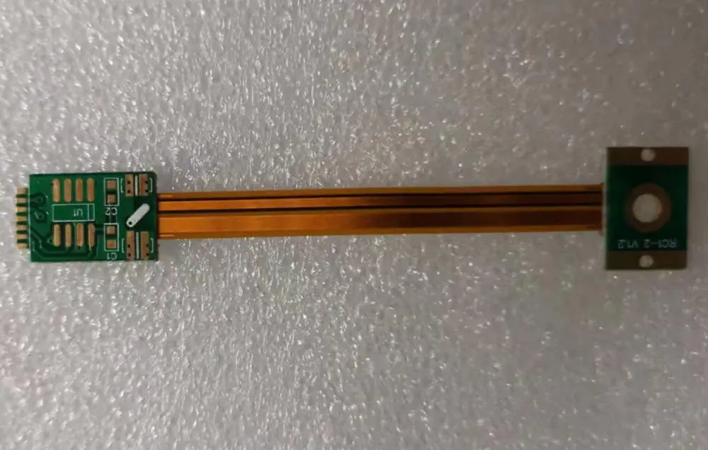
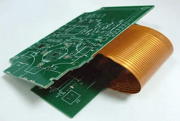
A Rigid-Flex PCB is a type of printed circuit board that combines both rigid circuit boards and flexible circuit boards. This board can be folded, bent, and twisted. This continuously flexed into any shape or curve during manufacturing. Furthermore, the flexible layers of this board are usually buried within the board. These layers penetrate through the rigid part of PCB.
Rigid-flex boards offer the flexibility of flexible PCB and durability of rigid PCB. These boards are very resistant to harsh application environment. Therefore, it is widely used in the medical and military industries. Rigid flex boards are different from flexible printed circuit boards or rigid printed circuit boards in terms of material and manufacturing process.
For over forty years,Customized rigid flex boards have been used in the high-performance applications. Rigid flex PCB manufacturers integrate layers of rigid and flexible materials to create rigid-flex boards. Also, copper plated vias connect rigid outer layers with inner flexible layers. Customized Rigid flex circuits offer more quality control and higher component density. Rigid designs are needed where there is requirement for extra support for SMT components while flexible designs are required in applications that need to flex and bend to fit into tight spaces.
Rigid-flex circuit boards provide optimum solutions for limited space conditions. These boards provide secure connection of device components while ensuring contact stability and polarity.
Benefits of Customized Rigid Flex PCBs
Rigid flex PCBs offers a lot of benefits which include:
Connection reliability
The foundation of Customized rigid flex PCBs lies in the connection of rigid layers with flexible cables. The combination of rigid layers and flexible layers gets rid of the need for wiring harness to connect rigid boards.
Lower part count
Rigid flex circuit boards need fewer interconnections and parts compared to traditional rigid boards. Therefore, they reduce the number of parts through the elimination of board-to board connectors and wire harness.
Flexible Design Options
The integration of flexible and rigid substrates in Rigid flex circuit boards made it easy for these boards to meet the requirements of highly complex and unimaginable configurations. Also, rigid flex circuit designs can integrate the following:
- Controlled impedance
- Reduced interconnections
- Highly complex configurations
- High layer count
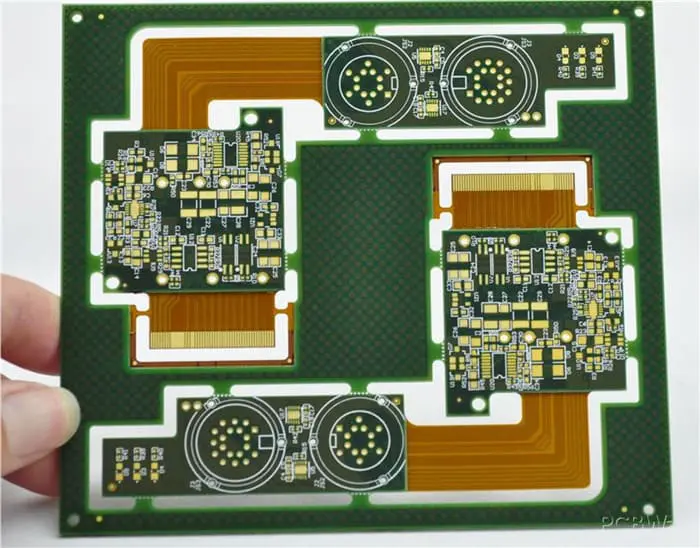
High density applications
Customized Rigid flex PCB helps to free up space by getting rid of interconnecting hardware. Therefore, this enables for greater connection density. The rigid parts of a rigid flex PCB are usually integrated for populating high density SMT devices. On the other hand, the flexible layers help to connect the rigid areas and as such, allows the circuit to be in a 3-dimensional shape. This circuit has several interconnected rigid areas on various planes.
Weight Reduction
Flexible circuit materials have very thin nature and they can create very narrow circuit traces. All of these make it possible to achieve higher connection density with a reduction in overall system weight. The low weight of rigid flex boards makes them suitable for use in extreme shock and vibration applications.
Applications of Customized Rigid Flex PCBs

Automotive industry
The automotive industry keeps experiencing new innovations and developments. Energy vehicles are the future development of this industry. Automotive wiring harnesses are quite complicated in connection. This doesn’t work well for the increasing quantities of electronic components required in new energy vehicles.
However, rigid flex PCB is an ideal replacement for wire harnesses since it offers design flexibility while being able to tolerate several dynamic bending without causing any damage to the wire. Furthermore, rigid flex boards offer a level of flexibility and rigidity which is ideal for automotive electronic components in extreme environmental conditions. Customized Rigid flex boards are widely used in the automotive industry. You will find them in car display, navigation and entertainment system.
Medical Wearables
In recent years, wearable devices have gained popularity in the medical field. Wearable devices like smartwatches and fitness trackers have been widely integrated to track people’s health and general well being. There are other wearables like smart clothes.
The advancement in technology has been a great help in the medical industry. It is crucial for medical practitioners to keep track of their patient’s wellbeing. This could involve monitoring a patient’s breathing patterns and heart rates. With the advent of wearable devices, medical professionals can get information about patients’ health regardless of where they are.
Most wearable devices integrate flex-rigid boards. Since these devices need to be compact, they require the integration of flexible and stiff components. Also, wearables must be able to operate under the stress of everyday activity. The integration of rigid layers offers the reliability that needed for these electronics to function in demanding situations.
Rigid Flex PCB Design
Guidelines for Rigid Flex PCB Design
One of the important stages of rigid Flex PCB manufacturing is the design stage. The design stage lays the foundation of the Customized rigid flex circuit. Therefore, it is crucial to understand some main elements during the design stage.
Rigid flex PCB designers need to adhere to laid down rules throughout the design process. Ensure the PCB corners aren’t bent when making them.
If at all you need to make a bend, make sure the bend is curved. Change the trace width gradually when doing so. This is because abrupt changes can result in a weak spot. Therefore, making use of at least two flex layers will enhance flexibility and as well reduce costs.
Guidelines for Rigid Flex PCB Layout
There are certain guidelines you need to maintain when creating a rigid flex PCB:
Trace Width
Ensure the trace width calculator delivers correct results for the trace width and spacing between its flexible parts. Furthermore, ensure the solder pads are completed in rounded styles.
Soldering Surface and Annular Rings
Rigid flex designers must ensure the annular rings and soldering surfaces are large enough. Stiffeners can help you to achieve the required thickness. However, you can apply coverlays on the flexible parts of the rigid flex PCB. This provides the conductors with protection and insulation. Cover lays are crucial during soldering as they restrain and hold the pads.
Also, the PCB manufacturer must ensure there are anchoring spurs on the pads. This helps to ensure a good bonding between the material and the copper during the rigid flex PCB assembly process.
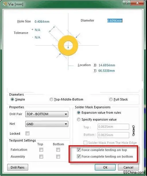
Vias
Ensure the plated vias are metalized. You can achieve this through the drilled holes. The holes connect conductive layers and flexible circuit. There must be connection between the blind vias and its inner layer. Also, you can integrate the buried vias. The buried vias and blind vias help connect the internal layers.
The integration of various types of vias will augment any space present in the circuit board. Also, this enables the addition of various component pads. This space helps in trace routing. Also, designers need to pay careful attention on accuracy when you calculating the bending radius of rigid flex PCB. This helps to prevent breakages.
Steps Involved in Designing the Rigid Flex PCB
There are several steps involved in Customized rigid flex PCB
Base material preparation
Before the fabrication process, the laminate must be thoroughly laminated. This process is very important, this is because copper coils have anti-tarnish features.
In this step, the copper coil will need to be dipped into an acidic solution. Alternatively, you can use the spraying method. After this, you can use various oxidation agents to coat the coil in an extensive manner.
Circuit pattern generation
This step involves the creation of circuit pattern. There are two major techniques for this; screen printing and photo imaging.
The initial method can help you generate the right circuit patterns. Screen printing can deposit on the surface of the substrate. The photo imaging technique is widely used. Also, this helps to ensure the dry photoresist film deposits on the substrate.
Etching
Etching involves dipping the substrate in an etch bath. Another method is using an etchant solution to spray the substrate. You can etch on the two sides to get the necessary results.
Drilling
In printed circuit boards, the holes, pads, and vias are usually drilled. Ensure your drilling tools can sustain a high speed. This will help you achieve precise holes. Also, it is advisable to create very small holes with laser drilling.
Through-hole Plating
Customized Rigid flex PCB manufacturers need care and precision in this step. After the hole has been drilled, the manufacturer will need to deposit a good amount of copper in it.
Cover Lay or Covercoat application
The next step after through-hole plating, the application of cover lay or Covercoat is the next step. Doing this will protect the bottom and top sides of the rigid-flex circuit. This will as well protect the circuit from all hostile environments, and solvents.
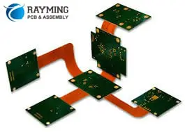
Types of Rigid flex PCB
Single sided Rigid-Flex PCB
Single sided rigid flex PCB features only one conductive layer. The other side of this board enables the integration of various electronic components on your PCB. Furthermore, single sided rigid-flex PCB compromise a single layer of rigid and flex substrates. This PCB is easy to manufacture compared to the other types of Customized rigid flex PCB.
Double Sided Rigid Flex PCB
Double sided rigid flex printed circuit board comprises one single rigid substrate layer and another layer of a flexible substrate. The flex layer provides flexibility while the rigid layer helps to enhance compactness.
Furthermore, double sided rigid flex printed circuit enables more routing traces. Double sided rigid flex boards are highly preferred among PCB engineers since they offer enough flexibility. Also the capability of this board helps in minimizing the board size.
Multilayer Rigid-Flex PCB
The multilayer rigid flex circuit board has at least three conductive layers of rigid and flexible substrates.
Limitations of the Rigid Flex PCB
Now that we know the benefits of Customized rigid-flex boards, let’s discuss some of its limitations.
Elaborate Manufacturing
Rigid flex PCB manufacturing require the integration of two substrates, one rigid layer and one flexible layer of substrate. The integration of these two substrates increases the time spent on production.
Labor intensive production
Rigid flex PCB manufacturing is both material intensive and labor intensive This is because of the variations and the sensitive nature of this antenna PCB.
Complex manufacturing process
The manufacturing process of the Customized rigid flex PCB is a complex one. It is different from the manufacturing process of other simpler PCBs. Also, this process requires the use of effective software. These factors contribute to the high cost of production.
Rules for Rigid-flex PCB Design
It is important to adhere to certain guidelines during rigid flex PCB design and manufacturing. These guidelines can serve as a checklist.
Make prior decision materials and manufacturing processes. This decision should be based on how much ‘flex’ your board requires. For example, if you are designing the circuit boards and you only need to fold them during the manufacturing process. You have to choose wisely:
- Number of layers
- Type and grade of copper
- Manufacturing method
However, if this circuit board is meant for applications exposed to extreme shocks and vibrations, you need to decide on:
- Adhesives
- Copper coils
- Number of layers
You should place copper traces to the circuit’s right angle since they work well when they positioned at the board’s right angle.
Therefore, it is crucial to stop bending at the corners. However, there are some considerations for PCB design that require bending at the corners. Use hatched polygons to retain the flexibility of the board. The integration of solid copper pours may minimize flexibility.
Copper can remove from the polyimide substrate because of the repeated stress from frequent bending. However, you can prevent this from happening by providing enough pad support to the exposed copper traces. Most times, the integration of surface mount pads is ineffective for this purpose. But, the use of anchoring stubs and coverlay openings can improve the pads’ reliability.
Conclusion
Flexible PCBs and rigid PCBs are different from Customized rigid-flex PCBs. Rigid flex printed circuit boards combine both flexible circuits and rigid boards. These boards are ideal for use in a wide range of applications.