
RAYPCB · ENGINEERING GUIDE
Stacked Vias: Microvia Interfaces, Reliability and Design Choices
Stacked vias place successive microvia connections above one another through build-up layers. The arrangement can save routing space, but it also makes the interfaces between stages central to the reliability discussion. Evaluate the actual materials, geometry and qualification evidence rather than treating the number of stacked levels as a complete risk model.
Draw every receiving interface
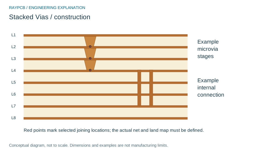
A stacked path includes the conductor at each layer and the connection to the next microvia. Show target and capture lands, filled structures where relevant, and the sequence that makes each surface available. The resulting drawing is more informative than a single vertical line across a stackup.
Compare a staggered alternative when space permits. Staggering changes the path and consumes lateral routing area; it is not an automatic guarantee of reliability. The choice must also respect signal routing, return paths and the construction the fabricator can qualify.
What the IPC warning means
IPC published an industry warning concerning weak microvia interfaces and failures that can appear after conventional inspection or later thermal exposure. That warning supports asking for representative qualification and continuity monitoring where applicable. It does not justify declaring every stacked microvia defective or assigning a universal safe number of levels.
Separate a static electrical pass from evidence under the thermal conditions required by the product. Also separate a visual cross-section from a test that can reveal an intermittent connection. A useful test plan states the construction, stimulus, monitored circuit and acceptance basis.
Count stages without calling the count a lifetime prediction
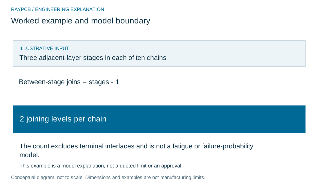
The worksheet counts successive adjacent-layer transitions and internal joining levels in an idealized chain. Three microvia stages span three dielectric intervals and have two joining levels between the stages. The bottom connection to its target and the top surface connection still exist; the tool labels its count narrowly rather than pretending to count every metallurgical boundary.
This arithmetic helps communicate a topology. It cannot calculate cycles to failure, probability of failure or suitability for a service environment. Those need appropriate evidence and engineering methods beyond layer counting.
Stacked-stage topology counter
Stacked-stage topology counter
Use the current inputs and keep the assumptions
Start with the example to understand the units and output, then use Clear for my inputs before entering your project. Example mode stays visibly labeled even if you edit its numbers. The form begins without a result so an illustrative value cannot be mistaken for an approved requirement. Every field must have a valid value; zero is accepted only where it has a meaningful role in the particular model.
Read the input notes before calculating. They identify the physical boundary and what is excluded. Keep the same unit convention across the drawing and worksheet. Changing an input invalidates the previous result and disables its download until you calculate again. This prevents an old number from appearing to describe a revised geometry.
The result is a screening record. A negative margin or an out-of-range condition identifies a question to resolve; a positive margin is not a manufacturing approval. Use the record with the actual drawing, material and project requirement. The model does not load CAD files, inspect images or retrieve private factory data.
Download the current result if it helps the discussion. The text includes the entered inputs, result and limitations. It stays on your device until you choose to attach or share it. Contact is a separate step; this page does not automatically populate the enquiry form or upload a file. Avoid confidential identifiers if you only need an exploratory calculation.
| Input | What to establish before using it |
|---|---|
| Review reference | Use a nonconfidential reference that lets you connect this calculation to the correct drawing revision. |
| Successive adjacent-layer microvia stages | Count distinct adjacent dielectric intervals in the ideal chain. A skip via or a more complex transition requires a separately drawn topology. |
| Number of equal chains | This is only a topology inventory. Repeating a geometry does not imply independent failures or a calculated reliability probability. |
Example: change the route, then revisit evidence
Suppose a dense package originally uses two successive microvia stages and a later layout revision adds a third. The change may affect the relevant interface set, processing and thermal history. Reusing the earlier qualification conclusion without examining that change is not a controlled review.
Document the alternative routing path, affected nets and proposed construction. If the third stage can be avoided by changing placement or a signal-layer assignment, compare that option before releasing a more complicated structure. The dense HDI stackup guide helps make that comparison at the architecture level.
Manufacturing questions with useful answers
Ask how the receiving surfaces are prepared, how filling and planarity are controlled, and which inspection opportunities exist before burial. Request evidence related to the actual geometry and material family. A statement that the supplier has made 'many HDI boards' does not identify the construction represented by a particular test result.
Avoid inserting process recipes into a customer drawing unless they are genuinely controlled requirements. Specify the required outcome and evidence, then have the process owner propose the qualified route.
Release and quotation implications
Keep the stackup, layer-pair map, material selection, thermal exposures and qualification scope together. If two quotations use different topologies, the lowest price may not describe the same deliverable. Ask for the architecture difference to be explicit before comparing cost or lead time.
Can all interfaces be assessed from one polished section? No: sample location and failure mechanism matter. Is a stacked path always required for any-layer HDI? The actual routing architecture determines that. Can a web tool certify the design? No; use its topology record to obtain a specific manufacturing and reliability review.
Review the architecture through its complete build sequence
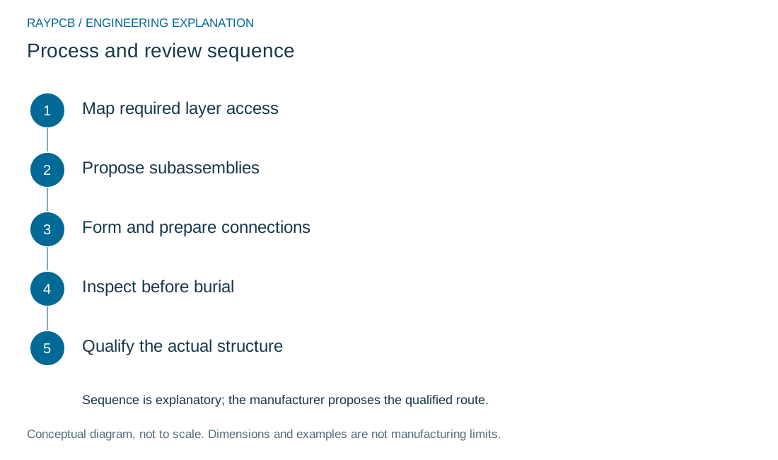
Create a layer-access map before optimizing individual dimensions. For each important net group, show where it starts, where it must reach and which reference structure accompanies the route. Then identify the physical interconnect used at each step. A line drawn between two layer numbers is only a connectivity requirement until the actual sequence of holes, lands and intermediate copper is defined.
Ask the fabricator to review the architecture while placement and routing choices are still flexible. A small early change to an escape pattern may avoid an additional specialized operation. A late change can affect the stackup, impedance, fabrication data and assembly land design at the same time. Record the dependencies so a cost reduction does not accidentally become an electrical or assembly regression.
Review the whole material and copper construction. The same nominal layer count can use different dielectric thicknesses, foil choices and internal connections. Material trade names alone do not describe the complete build. Keep the exact grade, relevant construction and approved alternatives with the stackup proposal. If a substitution changes the dielectric or thermal behavior, revisit the affected engineering requirements.
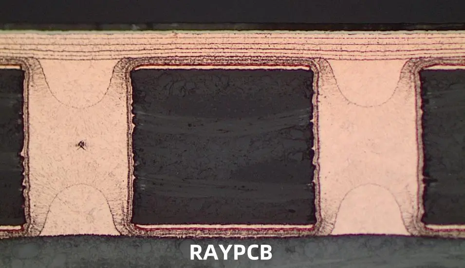
Inspection and qualification need a representative structure. Ask which geometries, layer spans and process stages a sample actually covers. A continuity check at room temperature and a test under relevant thermal exposure address different questions. A polished section is useful for understanding geometry at its location, but it cannot establish the behavior of every interface across all production conditions. Keep those limits visible when reviewing evidence.
The commercial comparison should use the same construction and acceptance scope. Separate a feasibility sample from a qualified recurring production route. Ask what is included in setup, coupons, inspection and any additional evidence work. Where the architecture remains open, request alternatives with their assumptions stated rather than allowing a low total to hide a different interconnect design.
Before release, reconcile the layer-access map with the actual CAD outputs. Confirm that each hole span exists where intended and that no obsolete pad stack remains in a dense region. Preserve the approved stackup, manufacturing proposal and open-item disposition together. The outcome should be a coherent construction that the design, fabrication and assembly teams can each interpret, not just a page of ambitious feature sizes.
Standards, source context and limits
Use the performance and acceptance documents named in the procurement agreement, including their revisions and any applicable addenda. A design guide explains choices; a product acceptance requirement defines what must be demonstrated. Neither a reference link nor a calculator result is a certification of the board or the supplier. Where a value is contractually important, check the controlled document and agree the measurement method with the responsible parties.
Examples on this page are deliberately labeled and are not advertised RAYPCB limits. Supplier documentation is linked for the specific material or process context it explains. Equipment photographs and cross-section examples show the subject; they are not current production, inspection or qualification records for your order.