RAYPCB · ENGINEERING GUIDE
BGA Pad Cratering: Diagnose Dielectric Cracks Beneath the Land
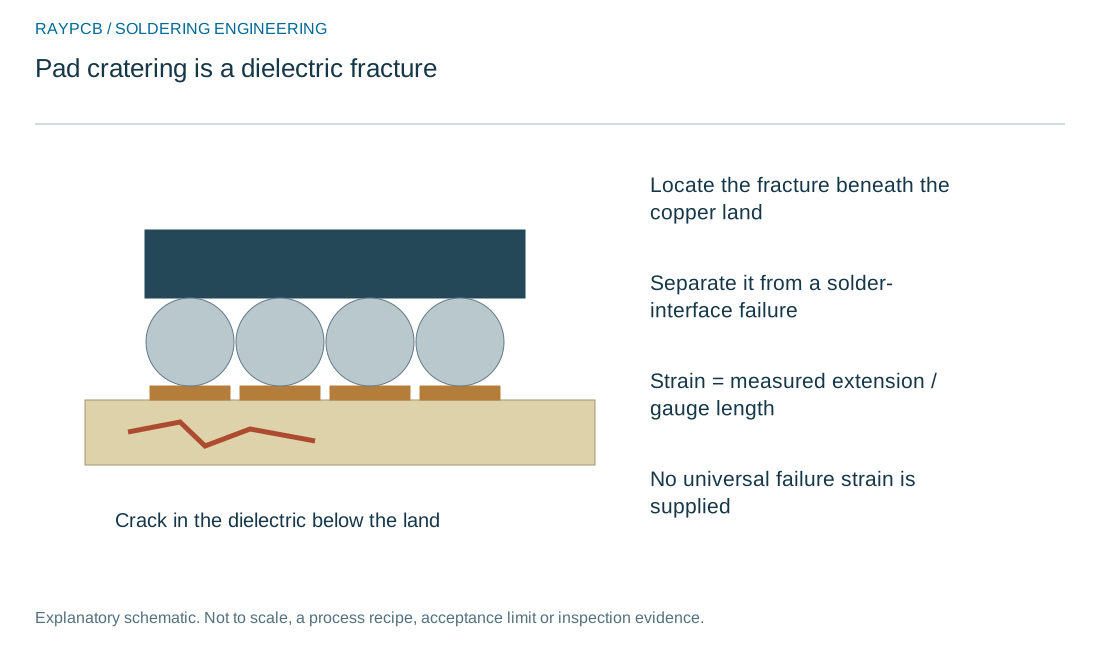
BGA pad cratering is cracking or fracture in the dielectric beneath a surface-mount land. It is a substrate failure near the solder connection, not a synonym for excess solder, a void inside a solder ball or copper being dissolved away by molten solder. The fracture location is central to the diagnosis.
This page explains how to distinguish the failure, preserve evidence and investigate the loads and construction involved. The strain worksheet converts an entered length change to engineering strain; it cannot predict a crater or set a safe board-bending limit for an unknown assembly.
Locate the fracture plane before choosing a remedy
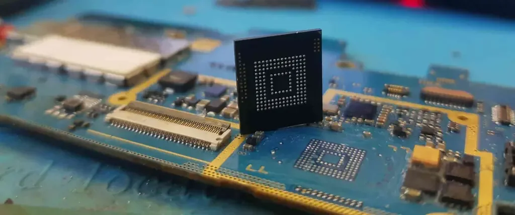
Different failure planes can exist near a BGA connection: within solder, at an interface, in a conductor or in the underlying laminate. A top-side pad that appears detached does not by itself establish which path occurred. Suitable sectioning or other failure-analysis evidence may be required.
The public scope of IPC-9708 describes methods for evaluating susceptibility to dielectric failure beneath SMT pads and notes that those methods do not define universal acceptance criteria. Use the applicable test method and agreed interpretation. Do not turn a generic pull-force result into a compliance claim without the defined specimen, procedure and requirement.
Review when the assembly is mechanically loaded
Depaneling, connector insertion, fixture clamping, test access, heatsink installation and handling can load a board after soldering. Service shock or vibration can introduce other conditions. Record the process stage where the electrical or physical anomaly first appears, rather than assuming reflow alone caused every crack.
Support placement, force application point and board shape matter. A fixture that reduces overall motion may still create a local stress concentration. Do not bend a suspect customer assembly repeatedly to reproduce a fault without an approved investigation plan; that can extend damage and obscure the original condition.
| Review item | What to establish |
|---|---|
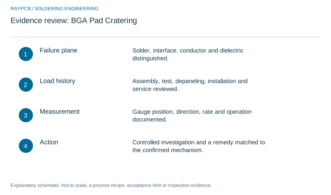
| Failure plane | Solder, interface, conductor and dielectric distinguished. |
| Load history | Assembly, test, depaneling, installation and service reviewed. |
| Measurement | Gauge position, direction, rate and operation documented. |
| Action | Controlled investigation and a remedy matched to the confirmed mechanism. |
Keep thermal history and material construction in the picture
The laminate, copper features, package, solder system and thermal sequence form a coupled structure. Exposure history and moisture can influence material behavior. A material described as high Tg is not automatically resistant to every pad-cratering mechanism, and Tg is not a direct measure of fracture toughness.
Retain the actual laminate identity and construction when comparing lots or proposed changes. The repeated-reflow record captures the process history; it does not replace material evidence. A blanket instruction to choose a thicker board or use a different solder mask is insufficient without understanding the relevant failure and design constraints.
Measure strain under a defined operation
Board-strain measurement needs a defined gauge arrangement, orientation, location, acquisition and loading operation. Strain at one location may not represent the local condition beneath every package corner. Direction and strain rate can matter, so a single maximum number needs context.
The elementary engineering-strain relation is length change divided by original gauge length. Multiplying by one million expresses microstrain. A 0.02 mm length change across 100 mm is 200 microstrain. That calculation illustrates units; it is not a substitute for a strain-gauge measurement or a safe limit for a BGA.
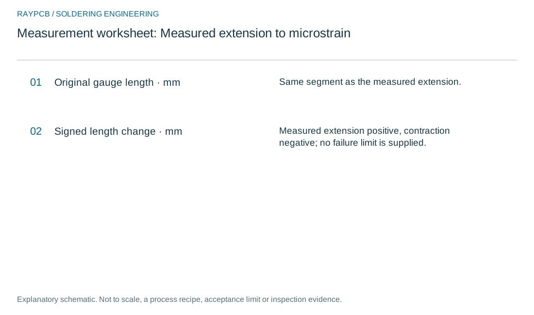
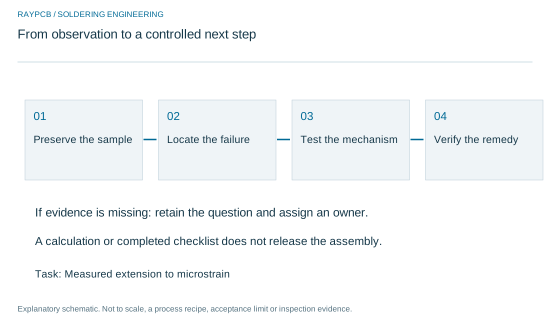
Measured extension to microstrain
Measured extension to microstrain
Use the current inputs and keep the assumptions
Choose the question you need to answer before entering numbers. Fields begin blank. Select Load example only to explore the model; example inputs are teaching values, not process recommendations or market prices. The example label remains visible after editing. Reset before preparing a record based entirely on your own data.
Use the displayed units and record the source of every input. Dimensions must share a reference and revision; temperature measurements must identify the location and method. An entered threshold or interval is your supplied review condition, not an IPC limit provided by this website. If a value is unknown, keep it open and obtain evidence rather than filling the space with a familiar number.
Read the assumptions alongside the result. A positive geometric margin answers only the stated calculation. It does not establish wetting, joint strength, production capability or compliance. A negative result remains visible so an incompatible assumption is not hidden. Checklist entries are self-reported and do not prove that the supporting documents were inspected.
Changing an input invalidates the displayed result and disables the download until the calculation is repeated. The text record includes inputs, results and limitations. Processing stays in this browser: no CAD data is read, no measurement system is connected and no information is automatically sent to Contact. Download and attach the record manually if it helps your enquiry. You can contact RAYPCB directly without using a tool.
| Input | What to establish before using it |
|---|---|
| Review reference | Use a nonconfidential revision/reference. |
| Original gauge length · mm | Same segment as the measured extension. |
| Signed length change · mm | Measured extension positive, contraction negative; no failure limit is supplied. |
Preserve samples for a useful failure analysis
Record package orientation, board side, suspected joints, electrical symptom and the handling stage. Keep unaltered specimens where appropriate before rework, dye-based analysis or sectioning changes the structure. Choose the analysis to answer a specific fracture-location question and document any artifacts the preparation could introduce.
A normal X-ray projection can fail to reveal a dielectric crack that does not produce a clearly resolved contrast change. Likewise, a static continuity pass may not exclude damage that has not fully interrupted the conductor. The evidence plan should state what each method can and cannot establish.
Test changes against the actual mechanism
Potential actions include changes to support, load application, depaneling, component placement, board construction or the thermal route. Select them according to the evidence. Changing solder volume because a page called the defect a solder crater addresses the wrong mechanism if the fracture is in the laminate.
Use representative specimens and defined loading conditions when comparing designs or materials. Preserve the baseline and report the failure modes as well as the measured values. If a test changes where failure occurs, a higher force alone may not be a complete improvement for the intended product.
Define disposition and prevention separately
A damaged substrate may need rejection or a specifically approved repair, depending on the product and location. Routine solder touch-up cannot restore an internal dielectric crack. The BGA rework process should therefore stop for assessment when substrate damage is suspected.
For RAYPCB review, provide the construction, package identity, failure images and method, process history, mechanical operation and available strain data. State the decision needed: containment, analysis, a fixture change or a next-revision design review. The BGA process-control guide connects the resulting evidence to a repeatable production plan without inventing a universal pass threshold.
Retain specimen identifiers with every image and measurement.
Separate the observed fracture from the proposed mechanism
Preserve representative failed and comparison samples before repair changes the interface. Record board and package identity, process history, mechanical events and how the fault was detected. A symptom such as an open circuit can arise at different physical locations, and those locations require different remedies.
Use examination suited to the suspected interface. A dielectric crack beneath a copper land differs from a separation within or between solder regions. An X-ray projection, external photograph and cross-section can reveal different information. State what the chosen method can and cannot resolve instead of treating one image as complete failure analysis.
Build the explanation from evidence. Material condition, thermal shape change, mechanical strain and process sequence may contribute, but their relevance must be tested. Do not attribute every post-reflow failure to excessive heat or every under-pad crack to a solder-volume problem.
Compare conditions without creating a universal threshold from a limited experiment. A susceptibility test can rank specimens under its method without defining a product acceptance limit. Similarly, a strain conversion can express a measurement in microstrain without predicting the strength of a particular pad/resin interface.
Select a corrective action that addresses the supported mechanism and evaluate possible side effects. A board-support change, material review, handling adjustment or print/process correction can have different consequences. Verify the change with the same failure definition and relevant product conditions.
For engineering review, send the marked failure location, examination method, relevant images and process history, plus the acceptance or reliability question. Identify what is known, what is inferred and what still needs examination. This makes the investigation traceable and prevents a confident-sounding generic remedy from replacing the actual evidence.
Standards, source context and limits
Use the references for their stated purpose. A material-vendor application note supports its specified material and conditions; a research paper reports the study it describes. Neither should be converted into a universal setting or a guarantee for a different assembly. Public standard summaries and contents are not complete normative requirements.
Agree the applicable controlled documents, revisions, acceptance basis and exceptions before production. IPC J-STD-001 concerns requirements for soldered assemblies, IPC-A-610 addresses assembly acceptability, and IPC-7711/7721 addresses rework, modification and repair procedures within its scope. Applicability must be established for the contract and task; this page does not certify compliance or reproduce paid acceptance tables.
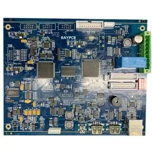
The photographs are selected from the existing RAYPCB website archive and illustrate relevant materials or operations. They do not establish current equipment ownership, certification or completion of your project. Original diagrams explain concepts and measurement boundaries; they are not inspection evidence or released manufacturing drawings.