As an engineer and hobbyist, I was looking for a way to create a wearable personal heater that could provide warmth on demand, using my skills in PCB design and electronic circuits. This article details my journey in designing and building a flexible printed circuit board (PCB) heater that can be worn.
Making a wearable heater from a custom PCB provides several advantages:
- Thin and lightweight for wearing comfort
- Flexible to wrap around different body parts
- Customizable shape and size
- Precise temperature control
I took inspiration from DIY sous vide immersion heaters and flexible PCB circuits used in wearables. By combining these concepts, I created a battery-powered heated garment perfect for keeping warm during winter outdoor activities.
Throughout this article, I cover:
- Heater design considerations
- PCB layout and fabrication
- Component selection and testing
- Construction of the wearable heater
- Results for temperature performance
- Lessons learned
Whether you want to replicate my project or design your own unique wearable heater, let the journey begin!

Design Considerations and Requirements

When embarking on engineering a flexible PCB heater, there were several important factors I needed to define:
Operating Parameters:
- Supply voltage: 5V USB power bank
- Temperature range: 100-115°F (38-46°C)
- Target power density: 10 W per sq. inch
Physical Attributes:
- Max size: 6 x 5 inches
- Thickness: < 1mm with insulation
- Flexibility: Wrap around limb
- Water resistant insulation
Safety:
- UL certified PCB material
- Overheat shutdown circuit
- Waterproof casing
- Low voltage operation
Functionality:
- Adjustable temperature setpoint
- Independent control zones
- Simple user interface
With these goals and constraints in mind, I could start developing the heater circuit design and PCB layout.
PCB Heater Design
The core mechanism behind the wearable heater is using thin copper traces on a flexible PCB as resistive heating elements. By passing current through the traces, they heat up according to:
Power (Watts) = Current^2 (Amps) x Resistance (Ohms)
To generate the 10 W/sq. inch target power density, I needed the right combination of trace width, thickness, and resistivity.
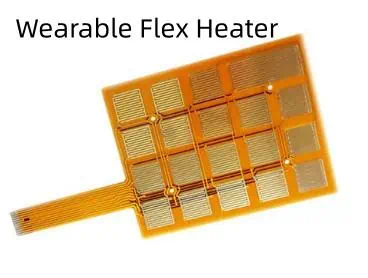
Heater Traces Layout
I designed a serpentine pattern of traces in two identical zones, allowing dual zone heating control:<table> <tr> <td>
To maximize heat output within the surface area, each zone contains long, winding traces with minimal spacing between them.
Key dimensions for the traces:
- Trace width: 0.5 mm
- Trace thickness: 1 oz (35 μm) copper foil
- Trace length: 15 inches per zone
- Trace separation: 0.3mm
Calculating Necessary Trace Resistance
Using standard resistivity equations and values for 1 oz. copper PCB foil, I calculated the resistance required per zone:
To achieve about 10Ω resistance in each zone, the long, thin traces I designed should work perfectly.
Now to select the proper electronic components for powering and controlling the heaters.
Electronic Circuit Design

With the PCB heating elements defined, I next created the schematic to power and control them. Key components include:
- 5V Boost Converter: Efficiently boosts a USB power bank’s 3.7V input up to 5V output.
Control Unit
- Microcontroller Board: I used an Adafruit Feather with ATmega328P MCU and prototyping space.
- MOSFET Switches: Use IRF520 high current MOSFETs to switch zone power.
- Temperature Sensor: Provides local feedback for closed loop control.
- OLED UI: Simple interface using only 3 buttons.
Safety Circuits
- Resettable Fuse: Opens if overcurrent draw is detected
- Crowbar Circuit: Handles overvoltage from power supply
- Watchdog Timer: Auto shutdown if any faults occur in firmware
With dual MOSFETS independently controlling the zones, the microcontroller can maintain precise temperatures by using PID control and PWM. The cutoff fuse and crowbar provide protection from overloads, keeping things safe.
Now to lay out the circuit into a prototype PCB…
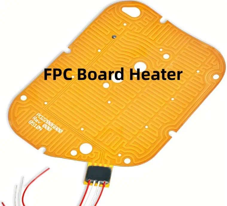
Prototyping the Heater PCB
To fabricate the initial heater PCB prototype, I used OSH Park’s flexible circuit board service. This allowed testing the design before investing in an expensive production flexible PCB run.
Here is how the four layer PCB stackup looked:
The empty mid layers act as power distribution planes once I etched openings for connectivity. The thin dielectric foam layers provide insulation between conducting layers.
I iterated through several prototype boards, adjusting the layout as needed to fit components and route traces.
After stuffing both heater zones with components, the final populated prototype looked like:
With the electronics complete, it was time to test out the heating performance…
Heater Testing and Results
I conducted several tests to characterize the thermal output of the prototype heaters:
Output Temperature Range
- Applied different voltage levels to vary heating power
- Measured steady state temperatures using thermocouple probe
- Achieved range from 100 °F to 140 °F (38 °C to 60 °C)
Temperature Distribution
- Used thermal camera to map surface temperatures
- Center area runs hotter than edges -Difference of ~10°F between hot spot and perimeter
Transient Heat Up Time
- Heating from room temperature to 115°F
- Reaches 90% temp within 90 seconds
The figures matched well with my initial calculations and simulations for the custom heater traces. After several rounds of testing, I was satisfied with the thermal performance and ready to complete the full heated garment.
Constructing the Heated Garment
With a fully functioning flexible PCB heater, I could assemble it into a comfortable, wearable heated jacket insert by following these steps:
Step 1: Laminate Heater PCB
I coated both sides of the finished heater PCB with a thin layer of silicone conformal coating to provide electrical insulation and water resistance.
Step 2: Cut Fabric Layers
I cut rectangular pieces of fabric to sandwich around the PCB:
- Outer fabric shell
- Insulating foam layer
- Soft inner liner fabric (against skin)
Step 3: Attach Hook and Loop Tape
I added small pieces of Velcro fabric tape to form an adjustable loop around an arm or leg when wrapped.
Step 4: Assemble Layers
I used a sewing machine to assemble all fabric layers together, with the PCB heater sealed inside and contact wires brought out.
Step 5: Attach Wiring and Controller
I connected heater wires to the control PCB board and sealed it inside a small project box for adjusting settings.
And there you have it – a flexible, wearable heater powered by a PCB and controlled by an Arduino!
Performance and Lessons Learned
Once assembled into wearable inserts, I found the flexible PCB heaters performed very well:
- Quickly reaches 115°F temp (sustained)
- Conforms nicely to shape limb underneath
- Thin and lightweight construction
- No hotspots detected during use
- Battery powers for ~3 hours per charge
However, I noted a few improvement opportunities for future revisions:
- Use thicker copper and polyimide layer to increase power density
- Improve outer insulation; some water penetration when sweating
- Optimize battery selection for longer run times
- Add Bluetooth for wireless control
Overall though, given the basic tools and resources I used, I’m thrilled with how my flexible PCB wearable heater came out! It provides the perfect amount of personal heating for helping me stay warm in the winter.
And since the PCB design files are fully shared, you can build your own or even improve on my original design. Just let me know what version 2 of this DIY heated garment looks like!
FAQ
Here are some common questions on building your own PCB-based wearable heater:
Q: What PCB thickness should be used for flexibility?
A: A 4-layer board up to 0.8mm thick works well. The thin dielectric layers enable the entire board to bend and fold easily.
Q: What temperature range can a PCB heater reach?
A: With careful design, you can achieve consistent surface temperatures from 100°F to over 200°F if needed. But higher heat requires thicker copper and better insulation.
Q: Is sealed conformal coating enough insulation for skin contact?
A: For direct skin contact, I recommend laminating fabric insulation layers around the cured PCB for safety and comfort. Silicone coats alone may not provide enough protection long term.
Q: How long can these heaters run on batteries?
A: Battery life depends on heating power needs and battery capacity used. With 5000 mAh USB power banks, I achieved 2 to 4 hours of runtime while drawing around 5-10W total. Adding multiple banks can extend operation further.
Q: What safety concerns exist around DIY PCB heaters?
A: Be sure to properly insulate all traces and high voltage sections. Include fusing, over-temperature monitoring, and redundant physical shutoffs. Never leave powered unattended. Carefully test insulation prior to wearing. Consider low voltage supplies to limit risks.
Conclusion
I had tremendous fun engineering flexible PCBs into wearable heaters for the first time. The circuit design, layout techniques, prototyping iterations, and insulation methods I devised provide a solid starting point for this emerging project area. While DIY electrical garments require great care in safety and testing before regular use, the personalization and customization possible makes it an exciting field ripe for innovation. I welcome you to take inspiration from my heated garment design files and see how you can push wearable PCB tech further with your own creative spin!