
RAYPCB · ENGINEERING REFERENCE
Drone PCB manufacturing: turn a design into a controlled build
Prepare civilian drone board construction, mechanical requirements and test information for manufacturing. Estimate the bare-board mass contribution without confusing it with aircraft performance.
Original engineering guidance · References checked September 28, 2026
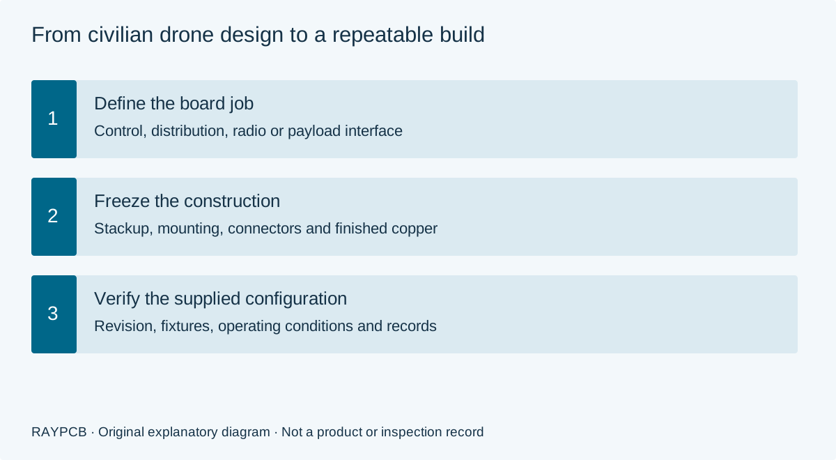
Drone PCB manufacturing starts with a defined board function
Drone PCB manufacturing turns a released circuit-board design into a repeatable physical construction. A civilian drone can contain flight-control, power-distribution, motor-control, radio and payload boards. Each has a different balance of mass, current, signal integrity, mechanical support and test access. Calling them all drone boards is not enough information for a useful fabrication quotation.
If you are still choosing processors, sensors, power rails or a system architecture, start with drone PCB design. This page begins at the manufacturing handoff: define the stackup and mechanics, estimate the bare-board mass contribution, prepare coherent production files and decide how the build will be checked. It addresses civilian equipment and does not establish aircraft airworthiness or operational approval.
The useful next step is a board-specific build brief. Identify what the PCB does, which interfaces it carries and what must remain unchanged between prototypes and repeat orders. A compact flight controller may prioritize sensor references and mounting, while a power board needs attention to finished copper, terminals and heat paths. Manufacturing choices should follow those tasks.
Estimate the bare-board mass contribution
The worksheet estimates dielectric and copper mass from your entered geometry. Dielectric thickness excludes copper. Copper coverage is an average fraction applied equally to each entered layer; it is not extracted from Gerber data. Use actual remaining board area if cutouts are to be included. The result excludes components, solder, mask, finish, connectors, coating, harnesses and hardware.
RAYPCB ENGINEERING
Industry EngineeringDrone PCB Manufacturing worksheet
Loading Drone PCB Manufacturing worksheet…
For the illustrative example, 60 cm² of board area, 0.9 mm total dielectric and 1.85 g/cm³ bulk dielectric density give 9.99 g of dielectric. Four copper layers at 35 µm and 50% average coverage add 3.7632 g using a copper density of 8.96 g/cm³. The combined estimate is 13.7532 g. The dielectric density is an example assumption, not a data-sheet claim for a named laminate.
This calculation helps compare construction assumptions before asking the fabricator for the approved stackup. It does not predict flight time, vibration response or mechanical strength. A lighter construction can require a different support arrangement or change electrical geometry. Verify the actual board and complete assembly after the construction is agreed.
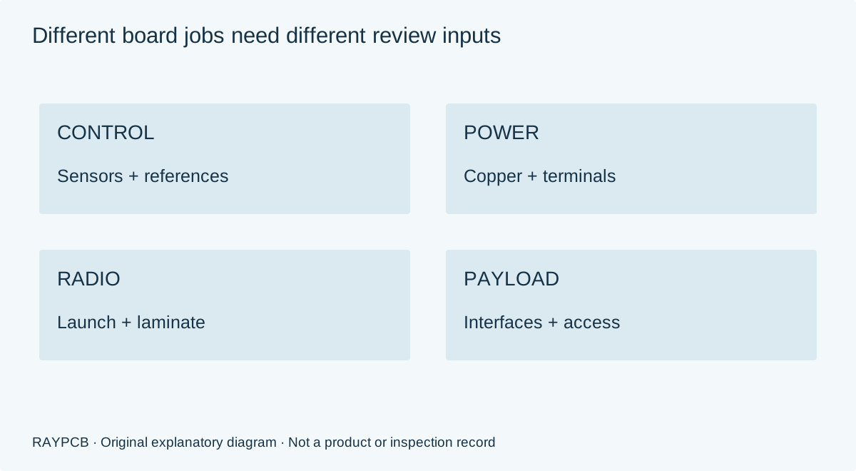
Match the build requirements to the board type
| Board function | Manufacturing inputs that deserve attention | Verification question |
|---|---|---|
| Flight controller | Stackup, reference planes, sensor region and mounting datums | Does the built assembly match the released mounting and signal configuration? |
| Power distribution | Finished copper, terminals, holes and local bottlenecks | What current and installed thermal condition will be tested? |
| Radio or antenna interface | Approved laminate, RF geometry and connector launch | Which impedance or RF evidence represents the supplied construction? |
| Payload or camera interface | Fine-pitch assembly, mechanical fit and connector orientation | How are links, programming and the populated variant checked? |
Avoid describing the entire drone with the maximum current of one subsystem. A signal board's copper requirements may differ substantially from a motor-power path. Likewise, a high processor clock does not automatically require an RF laminate throughout the board. Review the actual interfaces, electrical lengths and manufacturing constraints with the design owner.
When construction needs specialist materials, use the RF PCB hub to investigate the relevant family. Keep the exact material and layer assignment in the drone board release. Linking to a material family does not authorize the supplier to choose any grade in that family.
Freeze the stackup and finished copper definition
The stackup affects thickness, mass, stiffness, impedance and heat flow. Record layer order, reference structures, dielectric thickness assumptions and finished copper. A drawing that specifies only total thickness and layer count leaves important choices unresolved. Agree the construction before final routing dimensions become purchase requirements.
Use the mass worksheet for sensitivity, not for automatic stackup selection. If the dielectric thickness is reduced, review mounting span and vibration behavior. If copper is increased, check etching, pad geometry, assembly heating and mass. If layer count changes, revisit reference continuity and the locations of critical signals rather than treating the change as a purely mechanical edit.
For high-current routes, include terminals, plated holes, neck-downs and return conductors in the review. The broad power PCB guide explains why a trace calculation is only one part of the current path. Specify the final construction and verification needs; do not substitute an assumed copper-weight label for the required finished feature.
Treat mounting, vibration and connectors as manufacturing inputs
Define the board outline and hole pattern from a common datum. Include slots, keepouts, mounting hardware constraints and component-height limits. Check the mating direction of connectors and the clearance needed for a harness to bend without loading a solder joint. A correct board outline can still produce an unusable assembly if cable exit and access were omitted.
Flight-controller sensors can be sensitive to vibration and mounting conditions. The PX4 vibration-isolation guide explains this system-level concern. Its guidance does not specify your PCB fabrication tolerance or validate a mounting method for every controller. Record the intended support and isolation arrangement so prototype testing represents the eventual installation.
Keep heavy components and unsupported connectors in the mechanical review. Panelization and depaneling also matter: consider how the board will be supported during assembly and separated without loading sensitive regions. Share the populated view and proposed handling route when requesting an assembly quotation. Confirm the final panel and tooling rather than assuming the prototype panel automatically suits repeat production.
Prepare one coherent manufacturing release
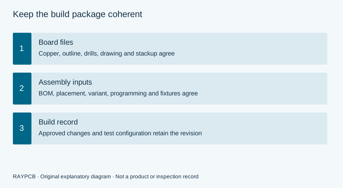
Include the fabrication layer set, drill data, outline, drawing and approved stackup under one revision. If assembly is included, add the BOM, placement data, assembly drawings and programming information. Name the populated variant and clearly identify do-not-fit positions. Use the required PCBA files guide to check the assembly handoff.
Do not mix a new copper export with an old drill file because the board outline looks unchanged. Open the output set together and compare units, layer mapping, registration and hole definitions. Mark intentionally omitted outputs. The released file package should stand on its own without requiring the supplier to reconstruct the designer's intent from several unrelated email attachments.
Record requested deviations and their disposition. A prototype change to a connector, copper region or component substitute can affect subsequent mechanical, electrical and firmware checks. Decide whether it is a one-build deviation or a new controlled revision, then ensure the files and purchase order say the same thing.
Connect board fabrication to the assembled configuration
A bare board cannot demonstrate sensor alignment, component orientation, firmware behavior or loaded power performance. If the manufacturing scope includes assembly, specify the exact component and firmware identities, programming interface, required fixtures and test conditions. For a small pilot, decide which activities are manual and which results must be recorded for each serial number or lot.
Fine-pitch devices may require additional inspection access or appropriate methods for hidden joints. The need depends on the package and agreed quality plan, not on the word drone. Keep visual inspection, electrical tests and functional tests distinct. A functional demonstration that the board starts up does not necessarily exercise every interface or fault response of interest.
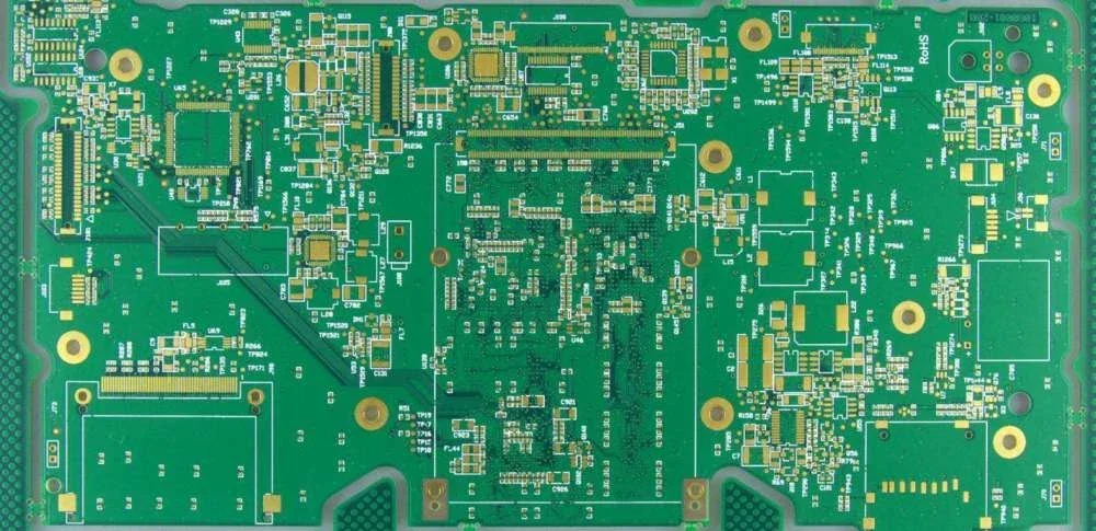
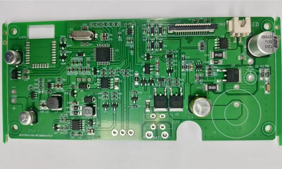
An assembled-board image can help communicate connector orientation and access, but it cannot measure electrical performance. The physical reference below illustrates component and connector density only. It is not presented as a tested drone flight controller or evidence of a particular customer's application.
Plan a representative bench verification build
Create a bench plan around the board's actual role. State the supply configuration, loads or interface fixtures, operating modes, measurement locations and acceptance source. Check power-up and programming separately from sustained loaded operation. Preserve the hardware and software revisions used for each result so later changes can be compared meaningfully.
For a power-distribution board, an open-air measurement can differ from the installed enclosure and harness. For a flight controller, mounting and vibration exposure can change sensor observations. For a radio board, connectors and nearby structures can influence the measured response. The common principle is to define the configuration before interpreting a result, rather than assuming every prototype test represents the final system.
This manufacturing review stops at evidence planning and the supplied board or assembly scope. System testing and operational approval remain separate responsibilities. Resolve discrepancies before repeating the build, and record whether a corrective action changed the board, the assembly process, the fixture or the test method.
A thinner board is not automatically a better drone board
Suppose a team reduces total dielectric thickness from 0.9 mm to 0.6 mm while retaining the example area and density. The estimated dielectric mass falls from 9.99 g to 6.66 g. Copper mass stays unchanged under the worksheet's equal-coverage assumptions. This is a 3.33 g change in the modeled bare-board contribution, not a measured reduction in the assembled aircraft.
Before releasing that change, examine support spacing, connector loads and the revised electrical construction. If reference distances changed, existing controlled-impedance dimensions may no longer apply. If additional support hardware becomes necessary, it contributes mass that the worksheet does not include. Document the approved construction and measure the completed build before updating the system mass budget.
The example demonstrates a useful engineering comparison without claiming a universal optimum. A manufacturing discussion becomes more productive when the team states which requirement is being improved and which others must remain satisfied.
Build an enquiry that can receive a useful response
Send the board function, fabrication files, drawing, target quantity, approved materials, dimensional requirements and needed verification records. For assembly, include the BOM, placement files, firmware and test scope. Identify whether mass, schedule or another constraint drives the decision, and mark unresolved values rather than presenting them as approved requirements.
Cost is influenced by layer construction, panel utilization, material availability, copper, holes, assembly complexity and test preparation. Separate one-time fixture and programming work from recurring board and assembly cost. Prototype quantities can carry a different share of setup cost from repeat orders, so compare quotations at the intended build quantities.
Use PCB Manufacturing for fabrication and prototype PCB assembly when the immediate task is an assembled validation build. You can contact the engineering team directly; completing the mass worksheet is optional and does not submit a quotation request automatically.
Drone PCB manufacturing questions
Does the mass tool calculate flight endurance?
No. It estimates an idealized dielectric and copper mass from entered dimensions and density. Aircraft endurance also depends on the complete vehicle, propulsion, battery, operation and environment, none of which is modeled here.
Can a prototype panel be reused for production?
Possibly, after reviewing handling, assembly support, separation and utilization. A panel convenient for a few boards may need changes for a repeatable production process. Keep the approved panel relationship with the board revision.
Should I specify a special material for every drone PCB?
No single material suits every board function. Select construction from the electrical, thermal, mechanical and manufacturing requirements, then verify the relevant properties and assembled behavior for that design.
Bring a focused question with the design revision
Send the board revision, construction, quantity and the layout, file or manufacturing question you need reviewed. Identify unresolved requirements so the response can address them.
Send requirements for reviewOptional: attach the downloaded worksheet manually. Use the worksheet as a discussion record; manufacturing requirements and verification must be agreed for the actual project.