Stripboard, also known as Veroboard, is a versatile and popular prototyping medium for electronic circuits. This comprehensive guide will walk you through the intricacies of creating circuits on stripboard, from understanding its basic structure to mastering advanced techniques for reliable and efficient circuit design.
Understanding Stripboard Basics
What is Stripboard?
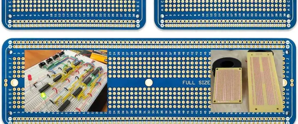
Stripboard is a type of prototyping board consisting of a rigid substrate with parallel copper tracks running in a single direction. Unlike breadboards, stripboard provides a more permanent solution for circuit development and testing. Its simple yet effective design makes it a favorite among hobbyists, students, and professional electronics engineers.
Key Characteristics of Stripboard
| Characteristic | Description |
| Material | Fiberglass or phenolic resin substrate |
| Copper Track Spacing | Typically 0.1 inches (2.54 mm) |
| Standard Sizes | Common sizes include 64×25 holes, 95×127 holes |
| Copper Track Direction | Parallel tracks running lengthwise |
| Conductivity | Continuous copper tracks allow easy connections |
Essential Tools for Stripboard Circuit Construction
Recommended Tools
- Cutting Tools
- Sharp craft knife
- Track cutting tool
- Small hacksaw or specialized stripboard cutter
- Soldering Equipment
- Soldering iron (15-25 watts recommended)
- Fine-tipped soldering iron bit
- High-quality solder (60/40 or lead-free)
- Solder wick or desoldering pump
- Measurement and Marking
- Ruler with 0.1-inch markings
- Fine-tipped permanent marker
- Digital caliper (optional but recommended)
Circuit Design Principles
Planning Your Circuit
Effective stripboard circuit design requires careful planning and consideration of several key factors:
- Component placement
- Track continuity
- Minimizing signal interference
- Thermal management
- Mechanical stability
Track Cutting Techniques
Basic Track Cutting Methods
- Manual Cutting
- Use a track cutting tool or sharp craft knife
- Cut perpendicular to the copper tracks
- Ensure clean, complete cuts
- Verify cut continuity with a multimeter
- Precision Cutting Tips
- Cut between holes, not through them
- Make multiple light passes
- Clean cut edges to prevent short circuits
Soldering Techniques for Stripboard
Soldering Best Practices
- Maintain clean soldering iron tip
- Use appropriate temperature (315-370°C)
- Apply solder sparingly
- Create smooth, concave solder joints
- Avoid cold joints and bridges
Common Soldering Mistakes to Avoid
| Mistake | Consequences | Prevention |
| Excessive Solder | Short circuits | Use minimal solder |
| Cold Joints | Poor electrical connection | Ensure proper heat and technique |
| Bridged Tracks | Unintended connections | Clean cuts, careful soldering |
| Overheating Components | Component damage | Use heat sinks, limit soldering time |
Advanced Stripboard Techniques
Component Mounting Strategies
- Vertical Mounting
- Ideal for space-constrained designs
- Provides better heat dissipation
- Reduces overall circuit height
- Horizontal Mounting
- Easier component placement
- Simplified track routing
- Better for larger components
Thermal Management
- Use copper tracks as heat sinks
- Separate heat-sensitive components
- Consider additional cooling methods for high-power circuits
Troubleshooting and Testing
Diagnostic Techniques
- Visual Inspection
- Check for solder bridges
- Verify component orientation
- Examine track cuts
- Electrical Testing
- Use multimeter for continuity testing
- Check voltage and current at key points
- Perform signal integrity tests
Frequently Asked Questions (FAQ)
Q1: How do I prevent short circuits on stripboard?
A: Carefully cut tracks between components, use insulating tape if needed, and always double-check your track cuts with a multimeter before powering the circuit.
Q2: Can I reuse a stripboard after desoldering components?
A: Yes, but be cautious. Excessive heating can damage copper tracks. Clean the board thoroughly and inspect for any track damage before reuse.
Q3: What’s the difference between stripboard and breadboard?
A: Stripboard provides a more permanent solution with soldered connections, while breadboards offer temporary, solderless prototyping with easy component replacement.
Q4: How precise do track cuts need to be?
A: Cuts should completely separate the copper track. Use a magnifying glass or continuity tester to verify complete separation.
Q5: Are there alternatives to manual track cutting?
A: Some advanced users employ chemical etching or laser cutting for precise track modifications, but manual cutting remains the most accessible method.
Conclusion
Mastering stripboard circuit construction requires practice, patience, and attention to detail. By understanding the fundamentals, investing in proper tools, and developing precise techniques, you can create robust and reliable electronic circuits.
Whether you’re a hobbyist, student, or professional, stripboard remains an invaluable tool in the electronics prototyping arsenal. Continual learning and experimentation will enhance your skills and expand your capabilities in electronic circuit design.