An encoder refers to a type of digital circuit. It takes input in binary forms and converts it into binary code. Here, a binary code refers to the input position and identifies the active input. Encoders are widely used in digital devices to convert a set of parallel inputs into a set of serial codes of output.
An encoder follows simple basic functional principles. It assigns a unique binary value to every input value. For instance, an encoder with 2-4 lines contains two lines of input and four lines of output. However, it assigns a unique binary code of 4-bit to both inputs with a combination of 2 exponents of 2 = 4. This encoder output usually comes in active low form. This means that it only gives one active low output at any specified time, whereas it gives inactive high output the rest of the time. The value of active output selects on the basis of the binary digits which assigns to an active input.

Encoders come in various types of forms. Some include priority encoders and binary-weighted encoders. Priority encoder sets a priority value for every input, whereas binary encoders use binary codes as inputs. In simple words, encoders refer to a type of digital system or circuit that uses binary inputs and converts them into a unique code of binary that represents the input location or position.
An encoder is a reverse logical circuit of a decoder. It contains a max line of input as two exponents of n and gives n number of output lines. Thus encoding the two exponents of n input value into an n number of output code. It generates a high active input in binary code corresponding to the input. Hereby, it encodes the two exponents of n lines of input in n number of output bits.
Types Of Encoder Circuit
Encoders have various types. Some of them include:
1. 4 to 2 Encoder Circuit
The Encoder 4 to 2 contains four inputs and two outputs. The input includes Y0, Y1, Y2, and Y3, whereas the output includes A0 and A1. here only one of the four inputs can have a ‘1” value to get an individual output binary code.
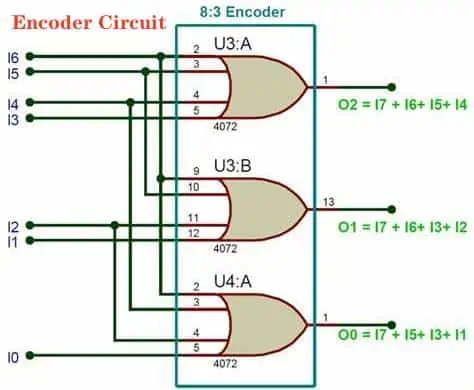
2. Octal To Binary Encoder Circuit
This encoder is octal to binary and contains eight inputs and three outputs. The inputs include Y0 to Y7, whereas the output includes A0, A1, and A2. In this, each line of input corresponds to 8 digits and gives three binary ode outputs.
3. Decimal To BCD Encoder Circuit
The encoder decimal to binary contains ten lines of inputs and gives four lines of outputs. In this, each line of input contains the decimal numbers, which gives four outputs in the binary code format. However, this encoder allows the input value in a decoded decimal digit, which encodes them into output binary code digits in the lines of output.
4. Priority Encoder Circuit
The priority encoder contains four inputs. These inputs include Y0, Y1, Y2, and Y3. it gives two outputs which include A0 and A1. In this, Y0 input contains the lowest input priority while Y3 contains the highest input priority. Here the input value has more ‘1’ simultaneously; then, the output comes in the binary code, which corresponds to the value of the input that has the highest priority.
People have to go through some errors while encoding the process. At the same time, some common errors include the following. When the value of all output comes to zero, it becomes complex and gives errors. Moreover, if the value of the input is High and comes twice and greater, then it creates an output that contains an error in the code.
However, to resolve these issues, make sure to set priorities for every encoder input. Thus it gives the value of the output code that corresponds to the value of the input with high priority.
Applications Of Encoder Circuit
Encoders serve as electrical circuit that is widely used in almost all types of digital systems. Encoders mainly use to convert decimal numbers into binary numbers to execute binary functions. These binary functions include division, multiplication, subtraction, and addition. Moreover, it is also used in applications that need to detect the interruption in the microprocessor.
Advantages Of Encoder Circuits In Digital Logic
· Reduction In The Number Of Lines
Encoders minimize the number of lines that need to transfer data from multiple signals input into one output value. However, simply changing the design reduces the component cost.
· Improved Reliability
Encoders can convert multiple input signals into just one serial code output. This enables the encoders to prevent errors during the data transmission.
· Improved Performance
Encoders reduce the input transmission time from various inputs to one output value. Hence automatically enhances the digital system performance.
Disadvantages Of Encoder Circuit

· Increased Complexity
Encoders seem simple circuits but come with more complexity than other multiplexers as they need additional types of components to execute.
· Limited To Specific Applications
Encoders can only be used in a type of application where a set of parallel inputs needs conversion in a serial code format.
· Limited Flexibility
Encoders have fixed flexibility. They only encode a limited amount of input numbers into a limited amount of output values.
Encoder Vs. Decoder
The Encoder circuit converts the analog or digital signals input into the binary-coded output format. Encoder uses an OR gate to convert the data into coded form. Moreover, encoders also accept input in ‘2 with an exponent’. Encoder uses input in the form of analog and digital signals. Moreover, it is a simple process.
Whereas the decoder converts back the coded binary numbers into their original signal format. It uses basic logic gates like NAND or AND gates. It converts the binary digits from n input lines into a max 2 with an n exponent’s output line. Decoder uses input in the form of coded binary digits. Moreover, it is quite a complex process.
Conclusion
Encoder is a special type of digital circuit. It comes with various types of features as well as disadvantages. However, using an encoder in the device depends on the system’s requirements and usage. Moreover, factors like cost, performance, reliability, and complexity also depict whether to use it or not.
Whereas decoder and encoder refer to logic circuits. However, both differ in performing their functions. The encoder encodes the signal data while the decoder decodes the data of the coded signal to get the exact message. Besides this, both the decoder and encoder offer various other beneficial features.