Introduction
In the rapidly evolving landscape of radar and communication systems, the performance integrity of Transmit/Receive (T/R) modules stands as a cornerstone of operational excellence. These sophisticated components serve as the critical interface between signal processing systems and the electromagnetic environment, making their rigorous testing and characterization essential for mission-critical applications.
T/R modules function as the central hub for controlling both signal transmission and reception in modern radar systems. Their performance characteristics directly influence communication clarity, radar accuracy, target detection capabilities, and overall system reliability. In complex electromagnetic environments where multiple signals compete for spectrum space and interference can compromise mission effectiveness, the linearity and distortion characteristics of these modules become paramount considerations.
The testing protocols for T/R modules encompass multiple performance parameters, including transmit power stability, spectral purity, receiver sensitivity, dynamic range, and nonlinear distortion characteristics. Among these parameters, Third-Order Intermodulation Distortion (IMD3) emerges as a critical metric that demands careful attention due to its significant impact on system performance in multi-signal environments.
This comprehensive guide focuses specifically on IMD3 testing methodologies, providing detailed insights into the theoretical foundations, practical testing procedures, and measurement techniques essential for ensuring optimal T/R module performance in demanding operational scenarios.
Understanding Intermodulation Distortion: Theoretical Foundation
The Nature of Nonlinear Systems
Intermodulation Distortion (IMD) represents one of the most significant challenges in RF and microwave system design. This phenomenon occurs when two or more frequency signals traverse a nonlinear system, generating additional spectral components that were not present in the original input signals. These unwanted frequency components, known as intermodulation products (IM products), arise directly from the nonlinear characteristics inherent in active devices such as amplifiers, mixers, and other signal processing components within T/R modules.
The mathematical foundation for understanding intermodulation products can be expressed through the general formula:
f<sub>IM</sub> = |m|f<sub>1</sub> + |n|f<sub>2</sub> + |p|f<sub>3</sub> + …
where m, n, p represent integer coefficients (positive or negative), and f<sub>1</sub>, f<sub>2</sub>, f<sub>3</sub> denote the fundamental frequency components present in the system.
Order Classification and Significance
The order (K) of any intermodulation product is determined by summing the absolute values of all coefficient terms:
K = |m| + |n| + |p| + …
This classification system helps engineers prioritize which intermodulation products require the most attention during system design and testing phases. Different orders of intermodulation products exhibit varying characteristics in terms of amplitude, frequency location, and impact on system performance.
Second-Order Intermodulation (IM2):
- Frequencies: f<sub>1</sub> + f<sub>2</sub> and f<sub>2</sub> – f<sub>1</sub>
- Generally easier to filter due to significant frequency separation from fundamentals
- Less problematic in most communication systems
Third-Order Intermodulation (IM3):
- Frequencies: 2f<sub>1</sub> – f<sub>2</sub> and 2f<sub>2</sub> – f<sub>1</sub>
- Most critical in system design due to proximity to fundamental frequencies
- Difficult to filter without affecting desired signals
- Primary focus of linearity testing protocols
Higher-Order Products:
- Fifth-order (IM5), seventh-order (IM7), and beyond
- Lower amplitude in mildly nonlinear systems
- Become significant in heavily compressed or saturated conditions
Third-Order Intermodulation: Critical Characteristics
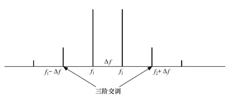
Third-order intermodulation products deserve special attention because they typically exhibit the highest amplitude among all intermodulation products in mildly nonlinear systems. More importantly, when the input consists of two closely spaced tones with frequencies f<sub>1</sub> and f<sub>2</sub>, the resulting IM3 products appear at frequencies 2f<sub>1</sub> – f<sub>2</sub> and 2f<sub>2</sub> – f<sub>1</sub>.
If the frequency separation between the two input tones is defined as Δf = f<sub>2</sub> – f<sub>1</sub> (where f<sub>2</sub> > f<sub>1</sub>), the third-order intermodulation frequencies appear at f<sub>1</sub> – Δf and f<sub>2</sub> + Δf. This frequency relationship is particularly problematic because these IM3 products fall very close to the fundamental frequencies, making them extremely difficult to remove through conventional filtering techniques.
When these intermodulation products fall within the receiver’s operating bandwidth, they create intermodulation interference that can significantly degrade communication performance, reduce signal-to-noise ratios, and compromise the system’s ability to detect weak signals in the presence of stronger interferers.
Practical Testing Implementation
Hardware Configuration and Setup
The practical implementation of IMD3 testing in T/R modules requires sophisticated test equipment and careful setup procedures. The standard approach involves generating a two-tone signal of equal amplitude and applying it to the Device Under Test (DUT), then measuring the resulting intermodulation components at the output.
Primary Equipment Requirements:
- Vector Network Analyzer (VNA) with four-port capability and internal combiner functionality
- Precision RF cables with appropriate connector types
- Calibrated attenuators and terminations
- Spectrum analyzer for detailed spectral analysis
- DC power supply for DUT biasing
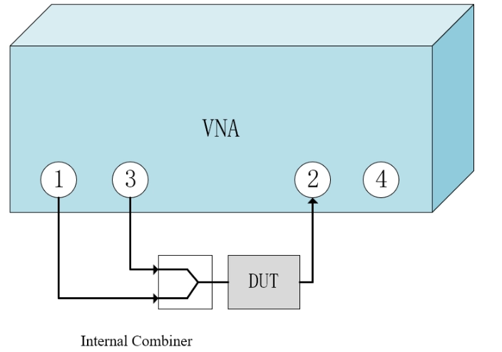
Connection Architecture: The R&S network analyzer configuration utilizes an internal combiner to merge individual single-tone signals from Port 1 and Port 3, creating a composite two-tone signal output through Port 1. This approach ensures precise amplitude and phase control of both fundamental tones while maintaining excellent isolation between signal paths.
- Port 1: Connected directly to the T/R module input (antenna port)
- Port 2: Connected to the T/R module output (combined port)
- Control Interface: Wave control command configured to set DUT to receive mode
Detailed Measurement Procedure
Step 1: Initial System Configuration
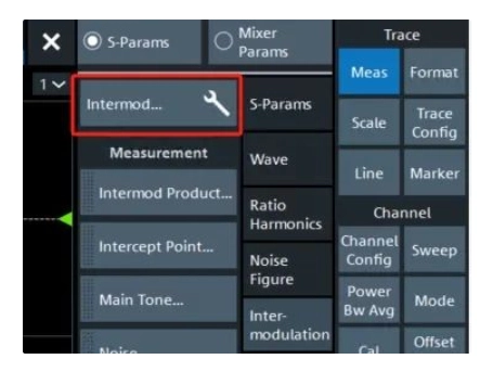
The measurement process begins with accessing the intermodulation measurement functions within the network analyzer interface. Navigate to the measurement menu and select: Meas → Inter-modulation → Intermod…
This selection opens the comprehensive IMD configuration dialog, providing access to all parameters necessary for accurate third-order intermodulation testing.
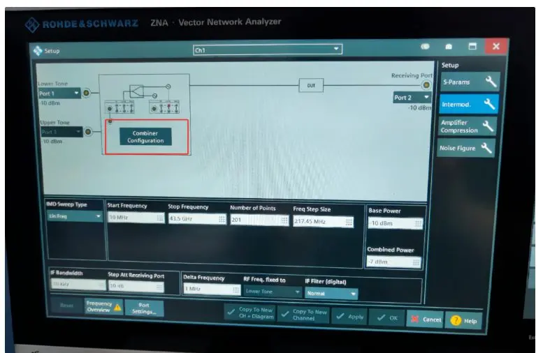
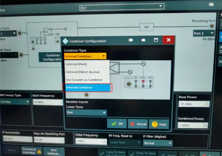
Step 2: Combiner Configuration
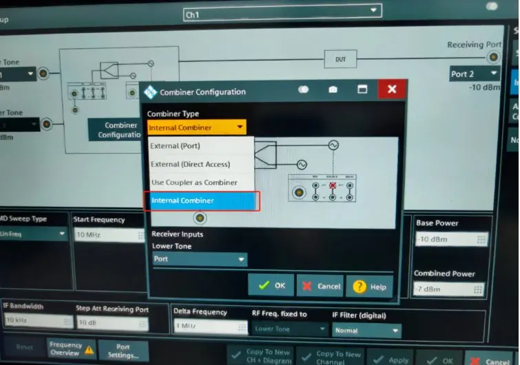
Access the detailed IMD configuration panel and locate the Combiner Configuration section. Select “Internal Combiner” to enable the network analyzer’s built-in signal combining functionality. This internal combiner ensures optimal signal integrity and minimizes external noise contributions that could compromise measurement accuracy.
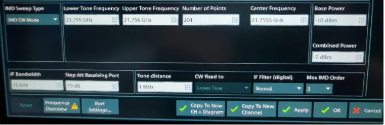
Step 3: Measurement Parameters
Configure the IMD Sweep Type to “IMD CW Mode” for continuous wave testing, which provides the most accurate representation of steady-state intermodulation performance. The key parameters requiring configuration include:
- Center Frequency: Set to the operating frequency of interest for the T/R module
- Tone Distance: Define the frequency spacing between the two fundamental tones
- Input Power Level: Establish appropriate power levels to achieve desired compression points
- Measurement Bandwidth: Configure resolution bandwidth for optimal signal-to-noise ratio
Step 4: Parameter Selection and Analysis
After completing the basic configuration, apply the settings and proceed to parameter selection. The measurement system provides several analysis options:
- Intermodulation Products: Direct measurement of IM3 spectral components
- Intermodulation Intercept Points: Calculation of theoretical intercept points
- IMD3: Ratio of IM3 power to fundamental tone power, expressed in dBc
- IP3: Third-order intercept point calculations
For comprehensive T/R module characterization, select “IM3MOR,” which represents the IMD3 measurement parameter most relevant to system performance evaluation.
Advanced Considerations and Best Practices

Measurement Accuracy Optimization
Achieving accurate IMD3 measurements requires careful attention to several factors that can influence results. System calibration procedures should be performed regularly, and measurement uncertainty analysis should account for instrument limitations, cable losses, and environmental variations.
Dynamic Range Considerations: The measurement system’s dynamic range must exceed the expected IMD3 levels by at least 10-15 dB to ensure accurate characterization. This requirement often necessitates the use of high-performance spectrum analyzers with exceptional spurious-free dynamic range specifications.
Power Level Selection: Input power levels should be carefully chosen to characterize the T/R module across its intended operating range. Testing at multiple power levels reveals the device’s compression characteristics and helps identify optimal operating points for specific applications.
Integration with System-Level Testing
IMD3 testing should be integrated with comprehensive T/R module characterization procedures that include gain compression measurements, phase linearity analysis, and thermal stability evaluation. This holistic approach ensures that all aspects of module performance are properly validated before system integration.
Conclusion
Third-order intermodulation distortion testing represents a critical aspect of T/R module validation that directly impacts system performance in real-world operating environments. The methodologies and procedures outlined in this guide provide the foundation for accurate, repeatable measurements that enable engineers to optimize system design and ensure reliable operation in demanding electromagnetic environments.
Proper implementation of these testing protocols contributes to enhanced radar system performance, improved communication clarity, and greater overall mission success in applications where signal integrity cannot be compromised. As RF systems continue to evolve toward higher frequencies and more complex operating scenarios, the importance of rigorous IMD3 testing will only continue to grow.
Through careful attention to measurement procedures, equipment calibration, and data analysis techniques, engineers can confidently characterize T/R module performance and make informed decisions about system design optimization and operational parameters.