The Reality of Electronic Component Failures
Electronics repair professionals encounter a sobering statistic: electrolytic capacitors can experience failure rates as high as 30% in certain applications. This figure isn’t meant to discourage, but rather to emphasize the critical importance of systematic troubleshooting approaches in modern electronics repair. Understanding component failure patterns, developing efficient diagnostic techniques, and implementing rapid repair strategies can transform challenging repairs into manageable tasks.
The complexity of modern electronic devices demands a methodical approach to fault diagnosis. Whether you’re dealing with consumer electronics, industrial control systems, or specialized equipment, the ability to quickly identify and resolve component failures directly impacts repair success rates and customer satisfaction. This comprehensive guide provides essential troubleshooting strategies for the most common electronic component failures, enabling both professional technicians and electronics enthusiasts to diagnose problems efficiently and implement effective solutions.
Understanding Electrolytic Capacitor Failures
Electrolytic capacitors represent one of the most vulnerable components in electronic circuits, with their failure mechanisms being both predictable and preventable through proper understanding. These components are particularly susceptible to environmental stresses, operating temperature variations, and voltage fluctuations that gradually degrade their performance over time.
Primary Failure Modes and Detection
The most common failure modes include capacitance reduction, where the capacitor loses its ability to store charge effectively, leading to inadequate filtering in power supply circuits. This manifests as increased ripple voltage, causing devices to operate intermittently or exhibit unstable performance. Leakage current represents another critical failure mode, where the dielectric material breaks down, allowing current to flow between the capacitor plates when it shouldn’t.
Short circuits in electrolytic capacitors create immediate and often dramatic failures, potentially damaging other circuit components and creating safety hazards. These failures typically occur suddenly and are easily identified through visual inspection or basic continuity testing. However, the most insidious failures are partial breakdowns that create intermittent problems, making diagnosis challenging without proper testing procedures.
Environmental Factors and Lifespan
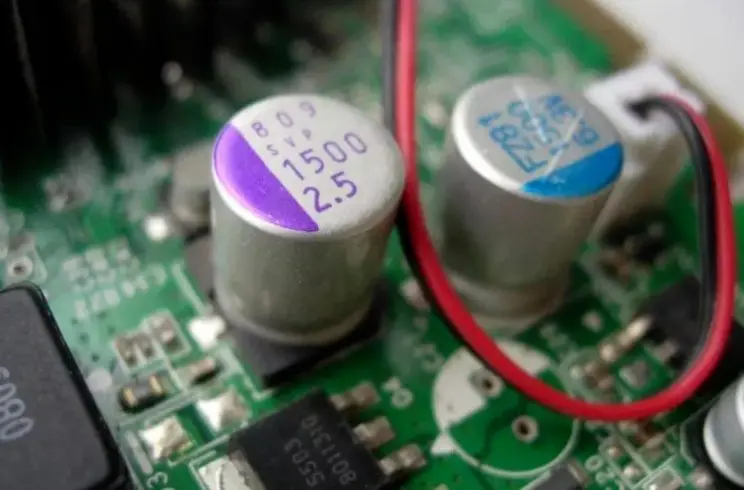
Heat exposure significantly accelerates electrolytic capacitor aging, with temperature increases of just 10°C potentially halving the component’s operational lifespan. Capacitors located near power transistors, voltage regulators, or other heat-generating components require prioritized inspection during troubleshooting procedures. Physical inspection should focus on signs of electrolyte leakage, bulging cases, or unusual heating during operation.
Diagnostic Techniques
Effective capacitor testing requires both visual inspection and electrical measurement. Begin with physical examination, looking for obvious signs of failure such as bulged tops, leaked electrolyte, or discoloration. Components that feel unusually warm during operation indicate internal problems requiring immediate attention. Electrical testing should include capacitance measurement, equivalent series resistance (ESR) testing, and leakage current evaluation using appropriate test equipment.
Resistor Failure Analysis and Detection
Resistor failures follow predictable patterns that experienced technicians learn to recognize quickly. Unlike capacitors, resistor failures are predominantly open circuits, with the component completely losing its ability to conduct current. This binary nature of resistor failure makes diagnosis relatively straightforward once you understand the failure patterns.
Failure Rate Correlation with Resistance Values
Statistical analysis of resistor failures reveals interesting patterns related to resistance values. Low-resistance components (below 100Ω) and high-resistance components (above 100kΩ) experience higher failure rates than mid-range values. This correlation relates to the physical construction and typical applications of these components.
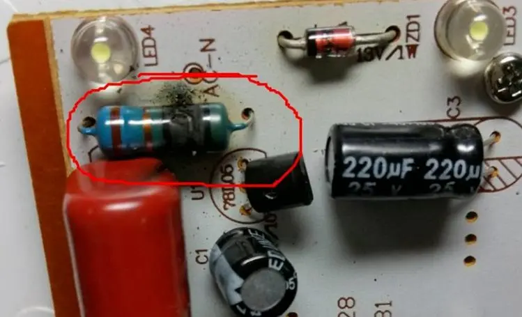
Low-resistance resistors often carry higher currents, generating more heat and mechanical stress within the component structure. These failures typically produce visible evidence, including discoloration, burning, or complete destruction of the resistor body. High-resistance resistors, while carrying minimal current, often operate in sensitive signal paths where environmental factors like humidity or contamination can significantly impact performance.
Visual Inspection Strategies
Developing efficient inspection techniques saves valuable troubleshooting time. Begin with low-resistance components, as their failures produce obvious visual cues. Look for charred or blackened resistor bodies, cracked cases, or components that appear physically damaged. These visual indicators typically correlate with complete failure, making replacement straightforward.
High-resistance resistors require more systematic testing since their failures rarely produce visible evidence. Use a systematic approach, testing suspected components with a digital multimeter while considering circuit loading effects that might influence readings. Remember that in-circuit measurements may not reflect actual component values due to parallel paths through other components.
Operational Amplifier Troubleshooting Techniques
Operational amplifiers serve dual roles in electronic circuits, functioning either as linear amplifiers or as comparators. Understanding which configuration you’re dealing with fundamentally changes the diagnostic approach and expected voltage relationships.
Linear Amplifier Configuration Analysis
When operational amplifiers function in linear amplifier configurations, the fundamental principle of virtual short between inputs applies. In properly functioning linear circuits, the voltage difference between the non-inverting (positive) and inverting (negative) inputs should remain minimal, typically less than 0.2V under normal operating conditions.
Voltage differences exceeding this threshold indicate amplifier damage, inadequate power supply voltages, or circuit configuration problems. Systematic voltage measurement at all amplifier pins provides comprehensive diagnostic information, including power supply integrity, input signal levels, and output stage functionality.
Comparator Configuration Considerations
Comparator applications intentionally create unequal input voltages, with the output switching between supply rail voltages based on input comparisons. In these circuits, significant voltage differences between inputs represent normal operation rather than failure indicators. Focus diagnostic efforts on output switching behavior, supply voltage stability, and reference voltage accuracy.
Power Supply and Biasing Verification
Operational amplifier circuits require stable, clean power supplies for proper operation. Verify both positive and negative supply voltages meet specification requirements, and check for adequate supply bypassing. Poor power supply decoupling creates instability, oscillation, or reduced performance that might be mistakenly attributed to amplifier failure.
Surface Mount Technology (SMT) Component Challenges
Modern electronics increasingly utilize surface mount components that present unique troubleshooting challenges due to their miniature size and dense packaging. Traditional test probes often prove too large for accurate measurements without risking component damage or creating short circuits between adjacent pins.
Specialized Testing Techniques
Innovative approaches to SMT testing include modifying standard test probes for precision work. Attaching sewing needles or fine wire probes to multimeter leads enables accurate contact with component terminals while minimizing short circuit risks. These modified probes can pierce through conformal coatings or flux residues that might prevent reliable electrical contact.
Consider investing in specialized SMT test equipment, including fine-tip probes, component pullers, and magnification tools that facilitate accurate diagnosis and repair work. Proper lighting and magnification significantly improve inspection accuracy and reduce eye strain during detailed component examination.
Power Supply Short Circuit Diagnosis
Power supply short circuits represent complex diagnostic challenges requiring systematic approaches to avoid component damage during testing. Traditional methods of applying full voltage while monitoring current can damage sensitive components or create safety hazards.
Controlled Current Testing Methods
Utilize adjustable power supplies with current limiting capabilities to safely diagnose short circuits. Set the voltage to the device’s normal operating level while limiting current to safe values, typically starting around 100mA. Gradually increase current while monitoring component temperatures using thermal detection methods.
Components that heat significantly under controlled current conditions typically indicate short circuit locations. This technique allows safe identification of problem areas without risking additional component damage. Ensure voltage polarity matches original specifications and never exceed the device’s voltage ratings during testing.
Thermal Imaging Applications
Infrared thermometers or thermal imaging cameras provide non-contact methods for identifying overheating components during controlled current testing. These tools enable rapid identification of problem areas while maintaining safe distances from potentially dangerous circuits.
Industrial Control Board Maintenance
Industrial environments subject control boards to harsh conditions including temperature extremes, vibration, contamination, and electrical noise. These environmental factors create specific failure patterns that require targeted maintenance approaches.
Contact Cleaning and Restoration
Poor electrical connections frequently cause intermittent operation in industrial control systems. Gold-plated edge connectors and card slots accumulate oxidation, contamination, and mechanical wear that degrades electrical contact integrity. Regular cleaning using appropriate techniques restores reliable operation while avoiding expensive board replacement.
Use pencil erasers to gently clean gold-plated contacts, removing oxidation and contamination without damaging the plating. Follow cleaning with contact enhancer application to provide long-term protection against future contamination. This simple maintenance procedure often resolves mysterious intermittent faults that might otherwise require extensive component replacement.
Intermittent Fault Diagnosis
Intermittent electrical faults present the most challenging diagnostic scenarios, often requiring patience and systematic elimination processes. These problems typically stem from thermal cycling effects, mechanical stress, contamination, or marginal component performance.
Environmental Factor Analysis
Poor thermal stability manifests as temperature-dependent failures where devices work correctly at some temperatures but fail at others. Identify these patterns by monitoring device behavior during temperature changes, using controlled heating or cooling to reproduce failure conditions.
Moisture and dust contamination create leakage paths and signal interference that produce unpredictable behavior. Visual inspection under magnification often reveals contamination patterns that correlate with problem symptoms. Cleaning procedures using appropriate solvents and techniques frequently resolve these issues permanently.
Software Parameter Considerations
Modern electronic devices increasingly rely on software configuration parameters that can create symptoms resembling hardware failures. Verify configuration settings, firmware versions, and calibration parameters before assuming hardware component failure. Documentation review and parameter verification often identify simple solutions to complex-appearing problems.
Conclusion
Effective electronics troubleshooting combines systematic diagnostic approaches with understanding of component failure patterns and environmental factors. The high failure rates observed in components like electrolytic capacitors emphasize the importance of developing efficient diagnostic skills and maintaining appropriate test equipment.
Success in electronics repair depends on patience, systematic approaches, and continuous learning about evolving component technologies and failure mechanisms. By implementing the techniques outlined in this guide, technicians can significantly improve their diagnostic accuracy and repair efficiency while minimizing component damage during testing procedures.