Selecting the appropriate thickness for your Printed Circuit Board (PCB) prototype is a crucial decision that can significantly impact the performance, durability, and overall success of your electronic project. This comprehensive guide will walk you through the various factors to consider when determining the ideal PCB thickness for your specific application.
Understanding PCB Thickness
What is PCB Thickness?
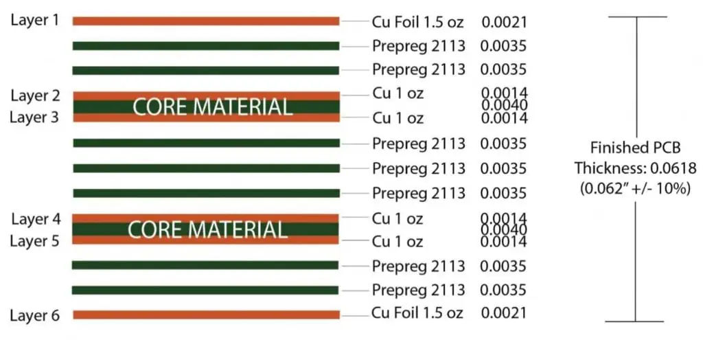
PCB thickness refers to the overall depth of the circuit board, including all layers of substrate, copper, and other materials used in its construction.
Standard PCB Thicknesses

While custom thicknesses are available, most PCB manufacturers offer standard options to choose from:
| Thickness (mm) | Thickness (inches) | Common Applications |
| 0.4 mm | 0.016″ | Flexible PCBs, wearables |
| 0.8 mm | 0.031″ | Mobile devices, thin electronics |
| 1.6 mm | 0.062″ | Standard thickness for most applications |
| 2.4 mm | 0.093″ | High-power applications, rugged devices |
| 3.2 mm | 0.125″ | Industrial equipment, power supplies |
Factors Influencing PCB Thickness Choice
1. Application Requirements
Consumer Electronics
Consumer electronics often require thinner PCBs to achieve compact designs.
Considerations for Consumer Electronics PCBs:
- Space constraints
- Weight limitations
- Heat dissipation
- Durability requirements
Industrial Applications
Industrial PCBs typically need to be more robust and may require thicker boards.
Factors for Industrial PCB Thickness:
- Vibration resistance
- Temperature extremes
- Exposure to harsh environments
- Long-term reliability
2. Mechanical Strength
The thickness of a PCB directly affects its mechanical strength and ability to withstand physical stress.
Relationship Between Thickness and Strength
| Thickness | Relative Strength | Suitable Applications |
| Thin (<1.0 mm) | Low | Flexible electronics, space-constrained devices |
| Medium (1.0-2.0 mm) | Moderate | Most consumer electronics, general-purpose devices |
| Thick (>2.0 mm) | High | Industrial equipment, high-stress environments |
3. Electrical Performance
PCB thickness can impact the electrical characteristics of your circuit.
Electrical Considerations:

- Impedance control
- Signal integrity
- EMI/EMC performance
- Power handling capacity
4. Thermal Management
The ability of a PCB to dissipate heat is partly dependent on its thickness.
Thermal Factors:
- Heat-generating components
- Copper weight and distribution
- Thermal vias and planes
- Ambient operating temperature
5. Component Compatibility
The choice of components can influence the required PCB thickness.
Component-Related Factors:
- Through-hole vs. surface mount technology
- BGA and other advanced package types
- Connector types and sizes
- Heat sinks and other mechanical attachments
6. Manufacturing Constraints
PCB thickness can affect the manufacturing process and associated costs.
Manufacturing Considerations:
- Minimum feature size and aspect ratio
- Via technology (through-hole, blind, buried)
- Layer count and stack-up design
- Production volume and cost
Selecting the Right Thickness for Different PCB Types
Single-Layer PCBs
Single-layer PCBs are the simplest type and are often used in basic electronic devices.
Recommended Thicknesses for Single-Layer PCBs:
- 0.8 mm – 1.6 mm for most applications
- Thinner (0.4 mm – 0.6 mm) for flexible or ultra-compact designs
- Thicker (2.4 mm+) for high-power or rugged applications
Double-Layer PCBs
Double-layer PCBs offer more design flexibility and are commonly used in various electronic devices.
Typical Thicknesses for Double-Layer PCBs:
- 1.6 mm is the most common thickness
- 0.8 mm – 1.2 mm for space-constrained applications
- 2.4 mm for increased durability or thermal management
Multi-Layer PCBs
Multi-layer PCBs are used in complex electronic systems and require careful consideration of thickness.
Thickness Guidelines for Multi-Layer PCBs:
| Layer Count | Recommended Thickness Range (mm) |
| 4 – 6 layers | 1.6 – 2.4 mm |
| 8 – 10 layers | 1.6 – 3.2 mm |
| 12+ layers | 2.4 – 3.2 mm or custom |
Special Considerations for Specific Applications
Flex and Rigid-Flex PCBs
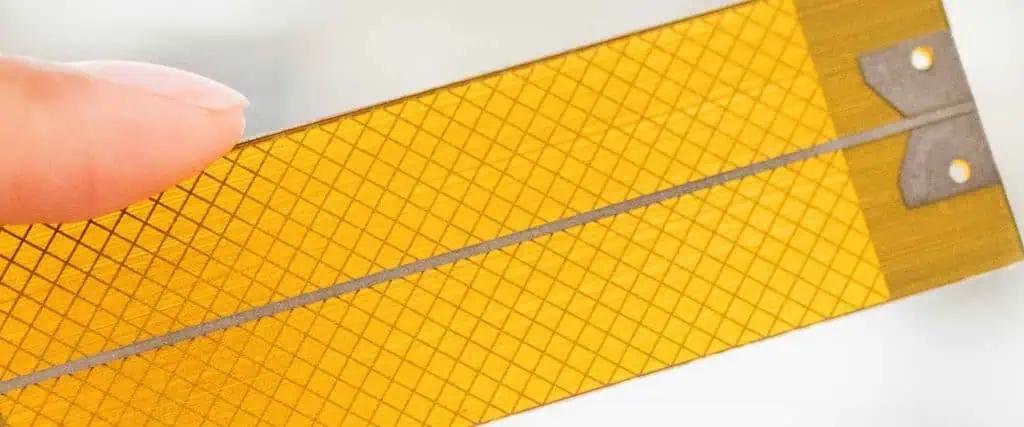
Flex and rigid-flex PCBs require special attention to thickness for optimal performance.
Flex PCB Thickness Considerations:

- Ultra-thin (0.1 mm – 0.2 mm) for maximum flexibility
- 0.3 mm – 0.6 mm for standard flex applications
- Consider the number of flex cycles required
Rigid-Flex PCB Thickness Factors:
- Thickness transition between rigid and flex sections
- Overall stack-up design
- Bend radius requirements
High-Frequency PCBs
High-frequency applications demand precise control over PCB thickness for optimal signal integrity.
High-Frequency PCB Thickness Factors:
- Dielectric constant of substrate materials
- Impedance control requirements
- Skin effect considerations
- Minimize thickness variations for consistent performance
Power Electronics PCBs
Power electronics often require thicker PCBs to handle high currents and thermal loads.
Power PCB Thickness Considerations:
- Copper weight and current-carrying capacity
- Thermal management requirements
- Voltage isolation needs
- Mechanical stress from heavy components
PCB Thickness and Cost Considerations
The thickness of your PCB can impact the overall cost of your project.
Cost Factors Related to PCB Thickness:
- Material usage
- Manufacturing complexity
- Yield rates
- Shipping and handling
Cost Impact of PCB Thickness
| Thickness Range | Relative Cost | Cost Factors |
| Thin (<1.0 mm) | Higher | Specialized materials, handling challenges |
| Standard (1.0-2.0 mm) | Baseline | Most economical for general purposes |
| Thick (>2.0 mm) | Higher | Increased material usage, longer processing times |
Best Practices for Choosing PCB Thickness
Follow these best practices to ensure you select the optimal thickness for your PCB prototype:
- Define Your Requirements: Clearly outline your project’s electrical, mechanical, and environmental needs.
- Consider Future Needs: Allow for potential upgrades or modifications in your thickness selection.
- Consult with Manufacturers: Leverage the expertise of PCB fabrication houses for guidance.
- Prototype Iterations: Test different thicknesses if possible to find the optimal balance of performance and cost.
- Balance Trade-offs: Weigh the pros and cons of different thicknesses against your project goals.
- Stay Standard When Possible: Use standard thicknesses unless your application absolutely requires a custom option.
- Think Holistically: Consider how thickness affects all aspects of your design, from electrical performance to manufacturing.
Emerging Trends in PCB Thickness
Stay ahead of the curve by considering these emerging trends in PCB thickness:
- Ultra-Thin PCBs: Advancements in materials and manufacturing are enabling ever-thinner PCBs for compact devices.
- Embedded Components: Integrating components within PCB layers is changing thickness requirements.
- 3D Printed Electronics: Additive manufacturing is allowing for more precise control over PCB thickness and structure.
- High-Density Interconnect (HDI): HDI technology is pushing the boundaries of thin, complex PCB designs.
- Advanced Materials: New substrate materials are offering improved performance at various thicknesses.
Frequently Asked Questions (FAQ)
1. How does PCB thickness affect signal integrity?
PCB thickness can significantly impact signal integrity, especially in high-speed or high-frequency applications. Thicker boards generally provide better signal integrity due to reduced crosstalk and improved impedance control. However, very thick boards can lead to longer via lengths, which may introduce signal degradation. The key is to find the right balance based on your specific application requirements, considering factors such as trace width, spacing, and layer stack-up design.
2. Can I use different thicknesses within the same PCB design?
Yes, it’s possible to use different thicknesses within the same PCB design, especially in rigid-flex PCBs. This approach, known as hybrid or step PCB design, allows for optimized thickness in different areas of the board. However, it requires careful planning and may increase manufacturing complexity and cost. Always consult with your PCB manufacturer to ensure feasibility and discuss any potential challenges.
3. How do I determine the minimum thickness for my PCB?
To determine the minimum thickness for your PCB, consider the following factors:
- Mechanical strength requirements
- Component types and sizes (especially for through-hole components)
- Electrical performance needs (e.g., impedance control, current-carrying capacity)
- Thermal management considerations
- Manufacturing limitations (e.g., aspect ratio for drilled holes)
- Environmental factors (e.g., vibration, temperature extremes)
Start with the thinnest standard thickness that meets all your requirements, then adjust as necessary based on prototyping and testing results.
4. What are the challenges associated with very thick PCBs?
While thick PCBs offer advantages in terms of strength and thermal management, they also present several challenges:
- Increased material costs
- Longer manufacturing times, especially for drilling and plating processes
- Difficulties in achieving high-aspect-ratio vias
- Potential for increased weight, which may be undesirable in some applications
- Challenges in creating uniform plating in through-holes
- Possible limitations in component selection due to lead length requirements
Always weigh these challenges against the benefits when considering very thick PCBs for your application.
5. How does PCB thickness affect the overall weight of my device?
PCB thickness directly impacts the weight of your device. As a general rule, doubling the thickness of a PCB will approximately double its weight, assuming the same board dimensions and materials. Here’s a rough guide for estimating PCB weight based on thickness (using standard FR-4 material):
| Thickness (mm) | Approximate Weight (g/cm²) |
| 0.8 mm | 0.15 g/cm² |
| 1.6 mm | 0.30 g/cm² |
| 2.4 mm | 0.45 g/cm² |
| 3.2 mm | 0.60 g/cm² |
Remember that these are approximate values and can vary based on copper weight, layer count, and specific materials used. For weight-sensitive applications, consider using thinner PCBs or exploring lightweight substrate materials.
In conclusion, choosing the right thickness for your PCB prototype is a critical decision that requires careful consideration of various factors. By understanding the impact of thickness on performance, manufacturability, and cost, you can make an informed decision that optimizes your PCB design for its intended application. Remember to consult with PCB manufacturers and consider prototyping different options to find the ideal thickness for your specific needs.
