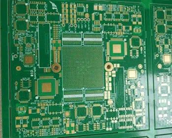
Rayming Is 16 Layer PCB manufacturer
Material:FR4,TG170 (ITE180).
Thickness: 2.0mm.
min hole: 0.2mm
min trace/space:0.11/0.11mm
200*300 mm per panel ,6 units/panel.
Immersion gold and press fit hole (tolerance 0.05mm)
16-Layer PCB Stackup Selector 16LPRO
Configure layer thicknesses for enterprise-grade 16-layer server, networking, and AI accelerator PCB designs
Quick Presets
Copper Layers (16)
Prepreg Layers (8)
Core Layers (7)
Stackup Visualization
2.8mm: Standard 16L
3.2mm: Server/networking
3.5-4.0mm: Backplanes, AI/HPC
Stripline: L3,5,7,10,12,14
Tightly-coupled: L8↔L9 center
L8-L9: Low-inductance decoupling
Symmetric: Balanced thermal
4 GND Planes: L2, L6, L9, L13 — Distributed ground reference every 4 layers minimizes return path inductance and provides EMI shielding.
4 PWR Planes: L4, L8, L11, L15 — Support multiple voltage rails (VCore, VIO, VDDA, etc.); L8-L9 form tightly-coupled power/ground pair for superior decoupling.
Signal Integrity: Every signal layer has an adjacent reference plane within 0.1-0.2mm for controlled impedance. Inner signal layers (L3,5,7,10,12,14) are fully shielded striplines.
Symmetry: Structure is symmetric about Core 4 center axis for optimal CTE matching, warpage control, and reflow reliability.
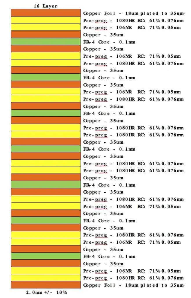
16 Layer PCB Stack Up
Introduction
Printed circuit boards with a high layer count are needed for complex, dense electronic designs. 16 layers is typical in many advanced control systems, telecom/networking and medical applications. The layer stackup requires careful planning to optimize electrical performance, thermal management and manufacturability.
This article provides guidelines on how to best use the 16 layers. We discuss recommended approaches for partitioning the layers into signal, ground and power distributions. A sample reference stackup is presented that can be tailored to specific system requirements. We also go over key considerations for 16 layer PCB design and fabrication.
Layer Planning Guidelines
Here are some principles to follow when planning out the layers in a 16-layer board:
- Split layers evenly between top and bottom of the board for symmetry. This avoids warping.
- Assign at least 20% layers for ground and 20% for power distribution. This leaves 60% for signals.
- Place ground and power layers adjacent to signal layers for controlled impedance and decoupling.
- Locate ground layers outermost as much as possible for easiest routing and heat dissipation.
- Assign one full uninterrupted ground plane layer on each side adjacent to signal layers.
- Define several split power planes to isolate analog, digital and high-current power.
- Order signal layers for optimized grouping based on high-speed, RF or isolated sections of the system.
Using these guidelines results in a versatile stackup suited for mixed-signal, digital and RF system designs.
16 Layer PCB Stackup Example

Here is an example 16 layer stackup designed using the above guidelines:
| Layer Number | Layer Type | Notes |
|---|---|---|
| 1 | Signal | Top-side RF/High-speed signals |
| 2 | Ground | Uninterrupted ground plane |
| 3 | Signal | Digital signals |
| 4 | Power | Split power planes – 3.3V, 1.2V |
| 5 | Signal | Digital signals |
| 6 | Ground | Uninterrupted ground plane |
| 7 | Signal | Analog signals |
| 8 | Power | Split power planes – 5V, 12V |
| 9 | Signal | Analog signals |
| 10 | Ground | Uninterrupted ground plane |
| 11 | Signal | Digital signals |
| 12 | Power | Split power planes – 1.8V, 2.5V |
| 13 | Signal | Digital signals |
| 14 | Ground | Uninterrupted ground plane |
| 15 | Signal | Bottom-side RF/High-speed signals |
| 16 | Ground | Uninterrupted ground plane |
This stackup ensures:
- Symmetric top and bottom layer distribution
- 40% of layers assigned for ground and 40% for various power domains
- Adjacent ground planes for controlled impedance routing
- Outer ground planes for easiest heat dissipation and routing
- Logical grouping of signal layers based on analog, digital, RF domains
The sequence can be modified to suit high density routing requirements and thermal design.
Key Design Considerations
Here are some key points to consider when designing a 16 layer PCB:
- Via technology – Laser drilled microvias with ~0.2mm holes allow dense interconnections between layers. Backdrilling clears unused sections of vias.
- Routing channels – Thinner dielectrics like 0.008″ prepregs between layers provide adequate trace routing channels.
- Controlled impedance – Ground + power layer next to signals allows impedance control for high-speed traces.
- Decoupling – Multiple power-ground pairs spread across layers provides decoupling capacitors access.
- Thermal – Thermal reliefs and thermal core layers help conduct heat out from inner layers.
- Signal integrity – Follow length matching, tuning and crosstalk guidelines for high-speed traces.
- ** manufacturability** – Work with fabricator early to check DFM, panel utilization, fabrication tolerances.
A disciplined approach is needed when laying out complex 16-layer designs while working closely with the PCB manufacturer to ensure producibility.
Fabrication and Testing Considerations
Here are some key considerations during fabrication and testing of densely packed 16 layer boards:
- Registration accuracy is critical for drilled holes to match pads across 16 layers when stacking up.
- Layer alignment must be highly precise over large board sizes typical of 16+ layer PCBs.
- Uniform heat dissipation across multilayer stackup requires careful processing during lamination.
- Plating quality and hole wall profiles should be strictly controlled for reliable interlayer connections.
- Electrical test coverage becomes more extensive with the high node count on large multilayer boards.
- Impedance control, signal integrity and RF performance testing requires advanced test equipment.
The fabrication facility must have proven experience in manufacturing complicated high layer count PCBs cost-effectively.
Recommendations When Ordering
- Partner with a fabricator experienced in building 16+ layer PCBs
- Request pre-DFM analysis before finalizing layer stackup
- Have quickturn prototypes made to validate design and process before committing to production
- Understand capabilities – layer tolerance, hole size ranges, line/space etc.
- Discuss any thermal design and signal integrity validation needs
- Review test coverage – bare board electrical testing, flying probe, ICT
- Get recommendations for optimal panel sizes, layout and breakout
Conclusion

A well-planned layer stackup strategy is key to effectively utilize the routing real-estate available in 16 layer designs. The layer sequence must balance signal routing needs, power distribution, heat dissipation and manufacture-ability constraints. A collaborative approach between designer and fabricator ensures a practical stackup optimized for cost, quality and performance. Rigorous design reviews and testing will validate the complex multilayer implementation before volume production.
Frequently Asked Questions
Here are some common FAQs about 16 layer PCB stackups:
What is a typical thickness for a 16 layer board?
A 16 layer board with standard 1oz copper and 0.008″ dielectric layers will result in a total thickness around 0.25″ (6.5mm). Thinner dielectrics can reduce thickness.
What are thermal cores used for in multilayer PCBs?
Thermal cores made of metallic or ceramic layers buried inside the stackup help conduct heat from inner layers to the board surfaces for efficient cooling.
What is backdrilling of PCB holes?
Backdrilling selectively removes the unused lower portions of through hole vias to avoid trapping heat inside multilayer boards. This improves thermal performance.
What are common dielectric materials used in 16 layer boards?
FR-4 glass epoxy is common. High frequency boards use RF materials like Rogers RO4350b. Flexible boards may use polyimide films. Ceramic filled PTFE substrates aid thermal conduction.
What testing is typically done on complicated multilayer PCBs?
Extensive bare board testing for shorts, opens, impedance control, signal integrity and review of fabrication quality before assembly and functional testing of populated boards.