In the world of electronics and printed circuit board (PCB) design, connectors play a crucial role in facilitating electrical connections between different components and boards. Among the various types of connectors available, Flexible Flat Cable (FFC), Board-to-Board (BTB), and Flying connectors stand out for their unique characteristics and applications. This comprehensive article will delve into the intricacies of these connectors, exploring their designs, functions, advantages, and roles in modern PCB assemblies.
Understanding Connectors in PCB Design
Before we dive into the specific types of connectors, it’s essential to understand the broader context of connectors in PCB design.
The Importance of Connectors
Connectors serve as the bridge between different electronic components, boards, and systems. They enable:
- Signal transmission
- Power distribution
- Data transfer
- Modular design and assembly
- Easy maintenance and replacement of components
Key Factors in Connector Selection
When choosing connectors for a PCB design, several factors must be considered:
- Electrical requirements (current, voltage, signal integrity)
- Mechanical constraints (size, shape, mating force)
- Environmental conditions (temperature, humidity, vibration)
- Reliability and durability
- Cost and availability
- Ease of assembly and maintenance
With this foundation, let’s explore FFC, BTB, and Flying connectors in detail.
Flexible Flat Cable (FFC) Connectors
What are FFC Connectors?
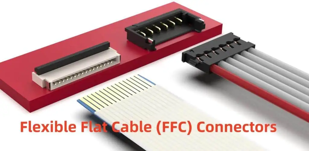
Flexible Flat Cable (FFC) connectors are designed to work with flat, flexible cables that contain multiple conducting strips running parallel to each other. These connectors are known for their low profile and ability to fit in tight spaces.
Key Characteristics of FFC Connectors
| Characteristic | Description |
| Cable Type | Flat, flexible with parallel conductors |
| Profile | Low and compact |
| Pitch | Typically 0.5mm to 1.25mm |
| Number of Pins | Ranges from 4 to 60+ |
| Mating Style | ZIF (Zero Insertion Force) or non-ZIF |
| Flexibility | High, allows for dynamic applications |
Advantages of FFC Connectors
- Space-saving design
- Flexibility for use in moving parts
- Good EMI/RFI shielding when properly designed
- Cost-effective for high-volume production
- Reliable performance in high-flex applications
Applications of FFC Connectors
FFC connectors find widespread use in:
- LCD displays and touch panels
- Printers and scanners
- Automotive dashboard electronics
- Mobile devices and laptops
- Medical equipment
Challenges and Considerations
While FFC connectors offer numerous advantages, they also present some challenges:
- Careful handling required to prevent damage
- Potential for signal degradation over long distances
- Limited current-carrying capacity compared to some alternatives
- Requires proper strain relief to prevent disconnection
Board-to-Board (BTB) Connectors
What are BTB Connectors?
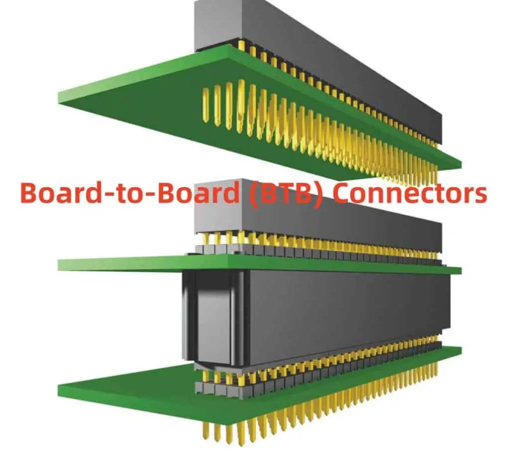
Board-to-Board (BTB) connectors, as the name suggests, are designed to connect two PCBs directly to each other. They come in various styles to accommodate different board orientations and spacing requirements.
Types of BTB Connectors
- Mezzanine Connectors: For parallel board stacking
- Card Edge Connectors: One board plugs directly into another
- Backplane Connectors: For connecting multiple boards to a main backplane
- High-Speed BTB Connectors: Designed for high-frequency signal transmission
Key Characteristics of BTB Connectors
| Characteristic | Description |
| Orientation | Parallel, perpendicular, or angled |
| Pitch | Ranges from 0.4mm to 2.54mm |
| Number of Pins | Can exceed 1000 for high-density applications |
| Stack Height | From <5mm to >30mm |
| Signal Integrity | Often designed for high-speed data transmission |
| Current Capacity | Varies widely based on design |
Advantages of BTB Connectors
- Enable compact, 3D PCB designs
- High-density interconnections
- Eliminate the need for cables in many applications
- Can be designed for high-speed signal transmission
- Available in various styles to suit different design requirements
Applications of BTB Connectors
BTB connectors are widely used in:
- Telecommunications equipment
- Server and data center hardware
- Industrial control systems
- Automotive electronics
- Consumer electronics (smartphones, tablets)
Challenges and Considerations
When working with BTB connectors, designers must consider:
- Mechanical stress and vibration tolerance
- Thermal management in high-density designs
- Signal integrity for high-speed applications
- Assembly and rework processes
- Cost implications for high-pin-count connectors
Flying Connectors
What are Flying Connectors?
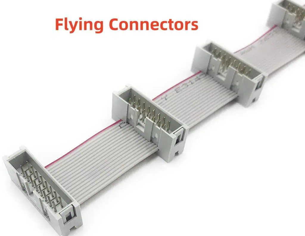
Flying connectors, also known as flying leads or wire-to-board connectors, consist of a connector attached to the end of a wire or cable. They provide a flexible means of connecting PCBs to other components or boards.
Types of Flying Connectors
- Crimp-style connectors: Wires are crimped to contacts
- IDC (Insulation Displacement Connector): Contacts pierce the wire insulation
- Soldered flying leads: Wires are soldered directly to the connector
- Plug-and-socket systems: Modular connectors with mating plugs and sockets
Key Characteristics of Flying Connectors
| Characteristic | Description |
| Wire Type | Single-core or multi-stranded |
| Wire Gauge | Typically 18-30 AWG |
| Connector Style | Various (crimp, IDC, modular) |
| Flexibility | High, allows for versatile connections |
| Current Capacity | Depends on wire gauge and connector design |
| Strain Relief | Often incorporated to protect connections |
Advantages of Flying Connectors
- Flexibility in board-to-device connections
- Ease of assembly and field replacements
- Can accommodate movements and vibrations
- Useful for prototyping and custom designs
- Allow for connections between boards at different angles or distances
Applications of Flying Connectors
Flying connectors are commonly used in:
- Automotive wiring harnesses
- Home appliances
- Industrial control panels
- Aerospace and defense equipment
- Medical devices
Challenges and Considerations
When using flying connectors, designers should be aware of:
- Potential for increased electromagnetic interference (EMI)
- Need for proper strain relief and wire management
- Quality control in crimping or soldering processes
- Space requirements for wire routing
- Potential for human error during manual assembly
Comparing FFC, BTB, and Flying Connectors
To better understand the strengths and weaknesses of each connector type, let’s compare them across several key factors:
| Factor | FFC Connectors | BTB Connectors | Flying Connectors |
| Space Efficiency | High | Very High | Moderate |
| Flexibility | High | Low | High |
| Signal Integrity | Good | Excellent | Moderate |
| Ease of Assembly | Moderate | Moderate | High |
| Cost | Low to Moderate | Moderate to High | Low to Moderate |
| Durability | Moderate | High | Moderate |
| Current Capacity | Low to Moderate | Moderate to High | Varies |
| EMI Shielding | Good | Excellent | Poor to Moderate |
Design Considerations and Best Practices
When incorporating FFC, BTB, or Flying connectors into PCB designs, consider the following best practices:
For FFC Connectors
- Ensure proper alignment and insertion of the cable
- Use strain relief to prevent cable damage
- Consider EMI shielding for sensitive applications
- Choose the appropriate pitch and number of conductors for the application
- Be mindful of the minimum bend radius of the flexible cable
For BTB Connectors
- Account for mechanical stress and vibration in the design
- Consider thermal management, especially in high-density designs
- Use appropriate stack height for the application
- Ensure proper alignment between mating connectors
- Consider signal integrity requirements for high-speed applications
For Flying Connectors
- Implement proper strain relief and wire management
- Use appropriate wire gauge for current requirements
- Consider modular designs for ease of maintenance
- Ensure proper crimping or soldering techniques are used
- Account for EMI considerations in sensitive circuits
Future Trends in Connector Technology
As electronics continue to evolve, connector technology is adapting to meet new challenges:
- Miniaturization: Connectors are becoming smaller while maintaining or improving performance.
- Higher Data Rates: Development of connectors capable of handling ever-increasing data transmission speeds.
- Improved Power Handling: Connectors that can manage higher currents in compact designs.
- Environmental Considerations: Focus on recyclable and eco-friendly connector materials.
- Smart Connectors: Integration of sensors and diagnostic capabilities within connectors.
Frequently Asked Questions (FAQ)
Q1: Can FFC connectors be used in high-vibration environments?
A1: While FFC connectors can be used in environments with some vibration, they are generally not the best choice for high-vibration applications. In such environments, it’s crucial to use proper strain relief and consider alternatives like ruggedized BTB connectors or specialized flying connectors designed for high-vibration scenarios. If FFC connectors must be used, additional mechanical support and vibration dampening measures should be implemented.
Q2: How do I choose between BTB connectors and flying connectors for my design?
A2: The choice between BTB and flying connectors depends on several factors:
- Space constraints: BTB connectors are generally more space-efficient.
- Flexibility requirements: Flying connectors offer more flexibility in positioning and movement.
- Signal integrity: BTB connectors typically offer better signal integrity for high-speed applications.
- Assembly process: Flying connectors can be easier to assemble and replace in the field.
- Cost considerations: BTB connectors can be more expensive, especially for high-pin-count applications.
Consider these factors in the context of your specific application to make the best choice.
Q3: Are there waterproof versions of FFC, BTB, and flying connectors?
A3: Yes, waterproof or water-resistant versions are available for all three connector types:
- FFC: Some manufacturers offer waterproof FFC connectors with IP67 or IP68 ratings.
- BTB: Sealed BTB connectors are available for harsh environment applications.
- Flying Connectors: Many flying connectors are designed with environmental sealing for use in automotive and outdoor applications.
When selecting waterproof connectors, ensure they meet the specific ingress protection (IP) rating required for your application.
Q4: How do I ensure signal integrity when using long FFC cables?
A4: To maintain signal integrity with long FFC cables:
- Use shielded FFC cables for sensitive signals.
- Implement proper grounding and shielding techniques.
- Consider using differential signaling for critical high-speed signals.
- Minimize the cable length where possible.
- Use signal conditioning or repeater circuits for very long runs.
- Choose FFCs with appropriate impedance characteristics for your application.
For very long distances or high-speed signals, consider alternatives like optical interconnects.
Q5: Can I mix different types of connectors in my PCB design?
A5: Yes, it’s common to use a combination of connector types in complex PCB designs. Each connector type has its strengths, and using a mix can optimize the overall design. For example:
- BTB connectors for high-density board-to-board connections
- FFC connectors for connecting to displays or flexible components
- Flying connectors for external device connections or where flexibility is needed
When mixing connector types, ensure compatibility in terms of signal levels, power requirements, and overall system design. Also, consider the assembly process and maintenance procedures when using multiple connector types.
In conclusion, FFC, BTB, and Flying connectors each play vital roles in modern PCB design. Understanding their characteristics, advantages, and limitations is crucial for creating efficient, reliable, and cost-effective electronic systems. As technology continues to advance, these connector types will evolve, offering new possibilities for innovative electronic designs.