Printed Circuit Board (PCB) design represents a significant portion of electronic product development costs, often accounting for 15-30% of total manufacturing expenses. As global competition intensifies and profit margins shrink, engineers and product managers must find innovative ways to optimize PCB design costs without compromising functionality or reliability. This comprehensive guide explores proven strategies to reduce PCB design expenses while maintaining quality standards.

Understanding PCB Cost Drivers
Material and Manufacturing Factors
The foundation of cost-effective PCB design begins with understanding what drives expenses. Raw materials typically constitute 40-60% of total PCB costs, with copper being the most significant contributor. The thickness of copper layers, number of layers, and substrate material directly impact pricing. Standard FR-4 substrates offer the best cost-to-performance ratio for most applications, while exotic materials like Rogers or Teflon should be reserved for high-frequency applications where they provide measurable benefits.
Manufacturing complexity adds substantial costs through specialized processes. Via types, drill sizes, trace widths, and spacing requirements all influence manufacturing difficulty and yield rates. Each additional manufacturing step introduces potential failure points and increases labor costs, making simplicity a valuable design principle.
Design Complexity Impact
Complex designs require more engineering hours, extended testing phases, and often multiple prototype iterations. Features like blind vias, buried vias, and microvias can increase costs by 200-500% compared to standard through-hole vias. Similarly, tight spacing requirements may necessitate advanced manufacturing processes that command premium pricing.
Strategic Design Approaches for Cost Reduction
Optimize Layer Count and Stack-up
One of the most impactful cost reduction strategies involves minimizing layer count while maintaining signal integrity. Each additional layer increases material costs and manufacturing complexity exponentially rather than linearly. A four-layer board typically costs 40-60% more than a two-layer equivalent, while an eight-layer board can cost 300-400% more.
Careful component placement and routing optimization often enables designers to achieve the same functionality with fewer layers. Mixed-signal designs benefit from proper ground plane management, which can eliminate the need for additional shielding layers. Power distribution networks can be optimized through strategic decoupling capacitor placement rather than dedicated power layers.
Standardize Design Rules and Specifications
Establishing and adhering to standard design rules across projects reduces manufacturing costs through improved yields and simplified processes. Standard via sizes, trace widths, and spacing requirements enable manufacturers to use proven processes and tooling, reducing setup costs and minimizing defects.
Creating design rule libraries that align with preferred manufacturers’ capabilities ensures compatibility and cost-effectiveness. These libraries should include standard drill sizes, minimum trace widths, and preferred component footprints that balance performance requirements with manufacturing constraints.
Component Selection and Placement Strategies

Choose Standard Components
Component selection significantly impacts both direct costs and manufacturing efficiency. Standard package sizes like 0603, 0805, and 1206 for passive components offer the best balance of cost, availability, and assembly reliability. Avoiding exotic packages reduces component costs and simplifies assembly processes.
Standardizing on common component values reduces inventory complexity and enables volume purchasing benefits. Using preferred manufacturer parts lists ensures long-term availability and competitive pricing. This approach also simplifies supply chain management and reduces the risk of component obsolescence.
Optimize Component Placement
Strategic component placement reduces PCB area requirements and simplifies routing, directly impacting costs. Grouping related components minimizes trace lengths and reduces electromagnetic interference, potentially eliminating the need for additional shielding or filtering components.
High-power components should be positioned to take advantage of natural heat dissipation paths, reducing the need for expensive thermal management solutions. Connector placement affects enclosure design costs and assembly complexity, making early coordination between PCB and mechanical designs essential.
Manufacturing and Assembly Considerations
Design for Manufacturability (DFM)
Implementing DFM principles from the project’s inception prevents costly redesigns and manufacturing delays. Standard drill sizes reduce tooling costs and improve yield rates. Manufacturers typically offer better pricing for designs using their preferred drill sizes and processes.
Panelization strategies can significantly reduce per-unit costs for small PCBs. Designing boards to fit efficiently within standard panel sizes maximizes material utilization and reduces waste. Proper panelization also improves assembly efficiency and reduces handling costs.
Assembly Optimization
Component orientation standardization reduces assembly time and potential errors. Aligning all polarized components in the same direction simplifies pick-and-place programming and reduces assembly errors. This approach also improves visual inspection efficiency and reduces testing time.
Test point accessibility and placement affect manufacturing test costs significantly. Well-designed test strategies reduce test time and improve fault detection rates, minimizing rework costs. In-circuit test (ICT) strategies should be considered during initial design phases rather than added later.
Advanced Cost Reduction Techniques
Multi-project Sharing
Combining multiple small projects into single manufacturing runs leverages economies of scale effectively. This approach works particularly well for companies with multiple product lines or when collaborating with partners on complementary products.
Shared tooling costs and setup fees can reduce per-unit expenses by 30-50% for small to medium volume runs. Careful coordination of project timelines enables this strategy without impacting individual project schedules.
Alternative Materials and Processes
Exploring alternative substrate materials can yield significant cost savings for appropriate applications. CEM-1 and CEM-3 substrates offer cost advantages over FR-4 for simple, low-frequency applications. However, these alternatives require careful evaluation of electrical and mechanical properties.
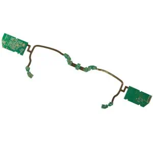
Flexible-rigid PCB designs can eliminate connectors and cables in some applications, reducing both material costs and assembly complexity. While the PCB itself may be more expensive, total system costs often decrease through simplified assembly and improved reliability.
Long-term Cost Management Strategies
Supplier Relationships and Volume Planning
Developing strong relationships with PCB manufacturers enables better pricing negotiations and priority treatment during capacity constraints. Long-term partnerships often result in preferential pricing and access to advanced manufacturing capabilities.
Volume forecasting accuracy directly impacts pricing structures. Manufacturers offer significant discounts for committed volumes, making accurate demand planning essential for cost optimization. Flexible manufacturing agreements can balance cost savings with inventory risk management.
Design Reuse and Standardization
Creating reusable design blocks and reference designs accelerates development while reducing engineering costs. Standard power supply circuits, communication interfaces, and protection circuits can be validated once and reused across multiple projects.
Platform-based design approaches enable cost amortization across product families. Common base designs with application-specific modifications reduce development time and leverage previous validation efforts.
Measuring and Monitoring Cost Effectiveness
Implementing cost tracking systems throughout the design process enables continuous improvement. Regular cost analysis helps identify trends and opportunities for further optimization. Key metrics include cost per square inch, component costs as percentage of total, and manufacturing yield rates.
Design review processes should include cost implications alongside technical considerations. Early identification of cost drivers enables proactive optimization rather than reactive cost reduction efforts.
Conclusion
Reducing PCB design costs requires a systematic approach that balances technical requirements with economic realities. Success comes from understanding cost drivers, implementing proven design strategies, and maintaining focus on manufacturability throughout the design process. The strategies outlined in this guide can typically reduce PCB costs by 20-40% while maintaining or improving product performance and reliability.
Cost optimization should be viewed as an ongoing process rather than a one-time effort. Regular review and refinement of design practices, supplier relationships, and manufacturing strategies ensures continued competitiveness in evolving markets. The investment in cost reduction strategies pays dividends through improved profit margins and market positioning.