During the production of electronic devices, some holes have to be drilled. Some years ago, PCB designers drilled simple holes to make their boards. Then, the circuit boards were moved onto the usual position and a lever began the drilling. After this, the same board would be moved to the next position for a repetition of this process.
As time went by, the circuit board became smaller and the manufacturing process became more complex. Therefore, this made the traditional drilling process impossible. These days, there are now standard drill sizes for circuit boards which make the drilling process much easier and even faster.
What are PCB Hole Sizes?
The printed circuit boards produced today are smaller in size and have more than 10,000 holes in different sizes. Although the automated CNC tools allow PCB manufacturers to drill any hope size without extra effort, this process is simpler with the standard drill sizes.
During the production of blank circuit board, there are some things you need to keep in mind. These are the purpose and the maintainability of the final PCB. Some circuit boards don’t have the necessary thickness to withstand every drill bit. So, it is recommended to ensure the hole size is less than your PCB aspect ratio.
You don’t just determine the hole size of your board, some factors do. A good example of such is the Vias. The sizes and shapes of Vias will usually vary and some things determine this. The complexity of a circuit determines the shape or size to use.
0.006 inches hole size is very small. For such holes, PCB manufacturers will need laser drills. However, the majority of builds will need “micro Vias.” Also, multiple size drills are usually a must if multiple board layers are involved.
Holes are usually drilled on every circuit board. These holes connect the board to the ground plane. This is because it is impossible to solder the hardware on the board. Sometimes, the PCB manufacturer adds some Vias to offer perfect ground connections. Also, these holes offer support to the circuit board when they are exposed to excess torque when the nut is being tightened.
How to Calculate PCB Hole Size

It is very easy to calculate the PCB hole size. All you need to do is to follow the necessary steps:
First, find the maximum diameter of the components. This determines the types and shapes of holes that needs to be drilled. You can use round holes if the PTH lead is round while the square shape is ideal for square PTH lead.
You can calculate the minimum size by determining the maximum Lead Diameter which could be +0.25mm or 0.20mm.
The next step is to determine the size of the annular ring. For level A, the size of the annular ring should be 0.05mm while 0.5mm should be for level B. Then 0.4mm for level C. This indicates that the pad diameter should be the sum of the minimum home size, minimum fabrication allowance, and minimum annular ring.
Calculating PCB Hole Diameter
The aspect ratio of a board determines the PCB determines the calculation of a PCB hole diameter. For instance, if the board thickness is 1.60mm, and the size of the hole is 0.49, the aspect ratio will be 1:4. When you reduce your board thickness, there should be a reduction in the aspect ratio.
The hole size diameter for a non-plated through hole differs from a plated through hole. For instance, when calculating for a non plated through-hole, you add the finished hole size and 0 mil.
On the other hand, calculating the hole size diameter for a plated through hole requires adding 0.10mm or 4 mil and the finished hole size.
What are the Standard PCB Hole Sizes?
There are various drill and hole sizes provided by the PCB industry. PCB manufacturers charge differently for hole sizes. While some PCB manufacturers charge for each drill size, some provide standard PCB hole sizes.
The PCB hole size chart provides PCB standard hole size in inches. A good number of PCB manufacturers offer their standard PCB hole sizes. The standard hole size can be calculated by subtracting the standard thickness of through-hole metal plating from standard drill bit sizes.
Furthermore, the printed circuit board must meet the specifications of the size state in the design drawing. This means the PCB must adhere to specifications like openings, cutouts, thickness, slots, and perimeter. The bonding must be within ±0.01millimeter and the error of the wire width must be within ±5%.
The engineer handling the drill press will be forced to use the next larger drill bit or choose the next smaller drill bit if there are no standard sizes. Also, the engineer may consider the PCB as non manufacturable.
PCB designers approximate the non-standard PCB hole sizes closer to the larger standard hole size. For instance, the holes drilled for DIP packages are usually approximated to 0.9mm diameter.
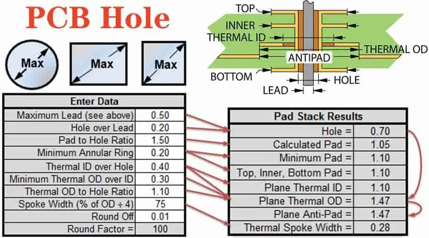
There are different standard PCB hole sizes. But, it is important to adhere to a simple rule in order to choose the best PCB hole size. Ensure your holes are 0.3mm wider than the component in order to get the best fit. For instance, if your component is 0.4mm, the hole size will be 0.7mm.
According to the SSS specifications, only 500 holes should be created on a circuit board . However, the DSS specifies that the maximum number of holes on a PCB should be 2000.
Importance of the PCB Hole Size Chart

One of the vital things that help you determine the hole size of a board is the PCB hole size chart. It is simply a description of the general information of holes. With this chart, a PCB designer will be certain of where to place components. In quite a number of cases, creating the holes via which components are placed can be a very complex process.
Due to this, PCB manufacturers must specify the dimensions and tolerance of the holes. In this case, the PCB hole size chart plays a huge role. A PCB hole size chart specifies important details about the hole size. Such information helps you plate the circuit board in the right way.
How to Get the Perfect PCB Drill Size
If you want to achieve the perfect drill size for your circuit board, look into these guidelines.
Know the lead diameter
You need to be sure of the lead diameter of thick components on your board. Also, you need to determine the maximum lead diameters from the datasheets.
Calculate the Minimum Hole Size
You can calculate the minimum hole size once you know the maximum lead. You will get the minimum hole size by adding 0.25mm to maximum lead diameter. i.e Minimum Hole Size = Maximum Lead Diameter + 0.25mm.
Calculate the pad diameter
The minimum hole size will help you get the value of the pad diameter. When calculating, use the smallest pad area. Most times, the value is always about 50 micrometers it 0.05mm. Furthermore, it is advisable to add a fabrication allowance when calculating the pad diameter.
Know the difference between the density level
There are different level of component densities. These are level A, B, and C. Level A is highly preferred among the PCB manufacturers. This is because it offers benefits such as low component density and high footprint geometries. On the other hand, the default standard for the majority of PCB projects is Level B. This level is commonly known for solid solder attachments. The last level which is C features a high design productivity standard.
How to Calculate PCB Through Hole Size
You need to take account of the right size of the plated through-hole and its pad when creating a through-hole PCB footprint. Using the right dimensions will prevent any issue from occuring during the PCB assembly. If the hole size is very small, this component pins can’t go into the hole. Therefore, the PCB layout has to be redone.
If there is a small distance between the pin’s edge and the hole’s wall, there won’t be a smooth flow of solder from one side of the board to the other. If otherwise, the solder will fill the hole. In these two cases, the components won’t solder firmly due to insufficient solder.
Also, if there is a small pad diameter is too small, there could be poor soldering connection.
There are four steps you need to follow to achieve accurate through hole size:
- Be certain of the performance classes and density of PCB design
- Find the lead diameter
- Know the size of the plated through-hole
- Get the pad diameter
Conclusion
PCB hole specifies the best location to place the through holes or copper pads. When fabricating a board, holes are usually drilled. In most cases, PCB holes are usually not plated through. It is important to note that any hole drilled in a circuit board needs to be carefully measured. Therefore, it is crucial to drill holes perfectly. PCB holes enable a board to achieve proper functioning.