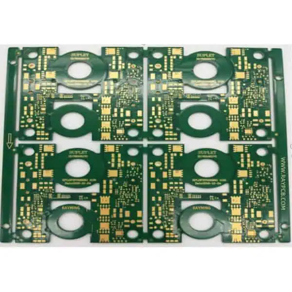
In the realm of electronic design, high-power printed circuit boards (PCBs) operating in high-temperature environments present a unique set of challenges. These specialized PCBs are crucial in various industries, including automotive, aerospace, industrial automation, and power electronics. This article delves into the intricacies of designing high-power PCBs capable of withstanding and performing optimally in elevated temperature conditions.

Understanding High-Power PCBs
Definition and Applications
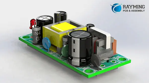
High-power PCBs are designed to handle significant electrical currents and dissipate large amounts of heat. They find applications in:
- Power supplies
- Motor controllers
- LED lighting systems
- Renewable energy systems
- Electric vehicle components
Challenges in High-Temperature Environments
Operating in high-temperature environments exacerbates the challenges faced by high-power PCBs:
- Increased thermal stress
- Accelerated component degradation
- Reduced electrical performance
- Material limitations
- Reliability concerns
Key Considerations in High-Power PCB Design
Thermal Management
Effective thermal management is paramount in high-power PCB design, especially in high-temperature environments.
Heat Dissipation Techniques
- Copper Pour: Maximizing copper coverage for better heat distribution
- Thermal Vias: Facilitating heat transfer between layers
- Heat Sinks: External components for enhanced cooling
- Active Cooling: Fans or liquid cooling systems for extreme cases
Thermal Simulation and Analysis
Utilizing thermal simulation software to:
- Identify hotspots
- Optimize component placement
- Validate cooling solutions
Material Selection
Choosing appropriate materials is crucial for high-temperature operation.
PCB Substrate Materials
| Material | Max Operating Temp (°C) | Thermal Conductivity (W/mK) | Relative Cost |
| FR-4 | 130 | 0.3 | Low |
| Polyimide | 260 | 0.3 | Medium |
| Aluminum | 150 | 150-170 | High |
| Ceramic | >300 | 20-270 | Very High |
Solder Mask and Surface Finish
Select high-temperature resistant options:
- High-Temp Solder Mask: Withstands temperatures up to 280°C
- ENIG (Electroless Nickel Immersion Gold): Suitable for high-temp applications
Component Selection and Placement
High-Temperature Components
Choose components rated for high-temperature operation:
- Ceramic capacitors with high voltage ratings
- High-temp resistors (e.g., metal film, wirewound)
- Semiconductors with extended temperature ranges
Component Placement Strategy
- Group high-heat components
- Maintain adequate spacing for thermal relief
- Consider airflow patterns in forced-air cooling designs
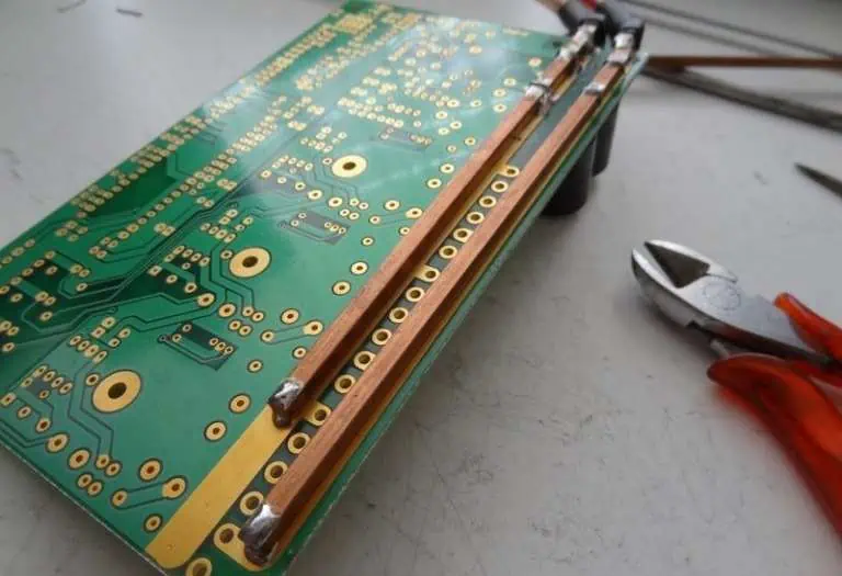
Power Distribution and Copper Weight
Copper Thickness
Increase copper weight for better current handling and heat dissipation:
| Copper Weight (oz) | Thickness (μm) | Current Capacity |
| 1 | 35 | Standard |
| 2 | 70 | Increased |
| 3 | 105 | High |
| 4 | 140 | Very High |
Power Planes and Trace Design
- Use wide traces for high-current paths
- Implement split power planes for different voltage domains
- Consider using buried or embedded power planes
Impedance Control and Signal Integrity
High temperatures can affect signal integrity. Implement:
- Controlled impedance routing
- Proper stackup design
- Signal isolation techniques
Reliability and Longevity Considerations
Thermal Cycling and Expansion
Address thermal expansion mismatches:
- Use materials with matched Coefficient of Thermal Expansion (CTE)
- Implement stress-relief design techniques
Conformal Coating
Apply conformal coating to protect against:
- Moisture
- Dust
- Chemical contaminants
Advanced Design Techniques
Multi-Layer PCB Design
Leverage multi-layer designs for improved thermal management and signal integrity:
- Dedicate layers for power distribution
- Use internal layers for signal routing
- Implement ground planes for better EMI shielding
Embedded Components
Consider embedding passive components:
- Reduces board size
- Improves thermal performance
- Enhances reliability in high-vibration environments
3D Design Considerations
Utilize 3D design techniques for:
- Optimizing component placement
- Integrating cooling solutions
- Improving overall board density
Manufacturing Considerations
PCB Fabrication
Select a fabricator experienced in high-power, high-temperature PCBs:
- Capability to handle thick copper
- Expertise in high-temp materials
- Advanced drilling and plating processes
Assembly Challenges
Address assembly challenges specific to high-temp designs:
- Use high-temperature solder alloys
- Implement special handling procedures for sensitive components
- Consider vapor phase soldering for uniform heating
Testing and Validation
Thermal Testing
Conduct comprehensive thermal testing:
- Temperature cycling tests
- Thermal imaging analysis
- Power cycling tests
Electrical Testing
Perform electrical tests under high-temperature conditions:
- Functional testing at elevated temperatures
- Accelerated life testing
- EMI/EMC testing in high-temp environments
Case Studies
Case Study 1: Automotive Power Module
Challenge: Design a power module for electric vehicle inverters operating in temperatures up to 150°C.
Solution:
- Used aluminum nitride ceramic substrate
- Implemented direct bonded copper (DBC) for improved thermal management
- Utilized high-temp SiC MOSFETs
- Integrated liquid cooling system
Outcome: Achieved reliable operation at 150°C with 30% improvement in power density.
Case Study 2: Industrial Motor Controller
Challenge: Develop a motor controller PCB for high-temperature industrial environments (up to 100°C ambient).
Solution:
- Selected polyimide substrate
- Implemented thick copper (3 oz) power planes
- Used conformal coating for environmental protection
- Designed custom heatsink with forced-air cooling
Outcome: Successful operation in 100°C ambient with 50% reduction in thermal-related failures.
Future Trends
Advanced Materials
Research into new materials for extreme environments:
- High-temperature polymers
- Ceramic-based composites
- Graphene-enhanced substrates
Wide Bandgap Semiconductors
Increasing adoption of wide bandgap semiconductors:
- Gallium Nitride (GaN)
- Silicon Carbide (SiC)
Integrated Cooling Solutions
Development of more efficient cooling techniques:
- Microfluidic cooling channels
- Phase-change materials
- Thermoelectric cooling integration
Conclusion
Designing high-power PCBs for high-temperature environments requires a multifaceted approach, combining material science, thermal management, electrical engineering, and manufacturing expertise. By carefully considering all aspects of the design process, from material selection to advanced cooling techniques, engineers can create robust and reliable PCBs capable of operating in the most demanding conditions.
As technology advances, new materials, components, and design techniques will continue to push the boundaries of what’s possible in high-power, high-temperature PCB design. Staying abreast of these developments and continuously refining design practices will be crucial for meeting the ever-increasing demands of industries relying on these specialized PCBs.
FAQ
Q1: What is considered a “high temperature” for PCB operation?
A1: In PCB design, “high temperature” typically refers to operating environments above 85°C. However, the exact definition can vary depending on the industry and application. For consumer electronics, temperatures above 70°C might be considered high, while in automotive or industrial applications, high temperature could mean operating at 125°C or even higher. For extreme applications, such as in oil and gas exploration or aerospace, high temperature could exceed 200°C.
Q2: How does high temperature affect the choice of PCB substrate material?
A2: High temperatures significantly impact the choice of PCB substrate material. Standard FR-4 materials typically have a maximum operating temperature of around 130°C. For higher temperatures, more specialized materials are required:
- High-Tg FR-4: Suitable for temperatures up to 170°C
- Polyimide: Can withstand temperatures up to 260°C
- Ceramic substrates: Capable of operating at temperatures exceeding 300°C
The choice depends not only on the maximum temperature but also on factors like thermal cycling, coefficient of thermal expansion (CTE), and cost considerations.
Q3: What are some key strategies for improving heat dissipation in high-power PCBs?
A3: Several strategies can be employed to improve heat dissipation in high-power PCBs:
- Increasing copper weight and using copper pours
- Implementing thermal vias to conduct heat between layers
- Using metal-core or insulated metal substrate (IMS) PCBs
- Integrating heat sinks or heat spreaders
- Designing for effective air or liquid cooling
- Optimizing component placement for better heat distribution
- Utilizing advanced thermal management materials like gap fillers or phase-change materials
The most effective approach often involves a combination of these strategies, tailored to the specific requirements of the design.
Q4: How do high temperatures affect the reliability and lifespan of PCB components?
A4: High temperatures can significantly impact the reliability and lifespan of PCB components:
- Accelerated aging: Heat accelerates chemical reactions that cause component degradation.
- Thermal stress: Repeated heating and cooling can lead to mechanical stress and eventual failure.
- Decreased performance: Many components show reduced efficiency or altered characteristics at high temperatures.
- Increased leakage currents: Higher temperatures can increase leakage in semiconductors.
- Reduced capacitor lifespan: Electrolytic capacitors, in particular, can dry out faster at high temperatures.
To mitigate these effects, designers must choose components rated for high-temperature operation, implement effective cooling solutions, and consider derating components to ensure they operate well within their specified limits.
Q5: What are the challenges in testing high-power PCBs designed for high-temperature environments?
A5: Testing high-power PCBs for high-temperature environments presents several challenges:
- Simulating realistic operating conditions: Creating test setups that accurately replicate the intended operating environment can be complex and expensive.
- Safety concerns: High-power, high-temperature testing can pose safety risks and require specialized equipment and procedures.
- Accelerated life testing: Predicting long-term reliability through accelerated testing requires careful planning and interpretation.
- Thermal cycling effects: Testing must account for the stresses induced by thermal cycling, not just steady-state high temperatures.
- Component interactions: High temperatures can affect component interactions in ways that might not be apparent in room-temperature testing.
- Equipment limitations: Standard test equipment may not be suitable for high-temperature operation, requiring specialized high-temp test gear.
Overcoming these challenges often requires a combination of sophisticated thermal chambers, custom test fixtures, specialized measurement equipment, and carefully designed test protocols.


