Aluminum PCBs (Metal Core PCBs or MCPCBs) have become increasingly important in high-power electronic applications due to their superior thermal management capabilities. This article explores the fundamentals of heat dissipation in aluminum PCBs and presents comprehensive design methodologies for optimal thermal performance.
Fundamentals of Aluminum PCB Construction
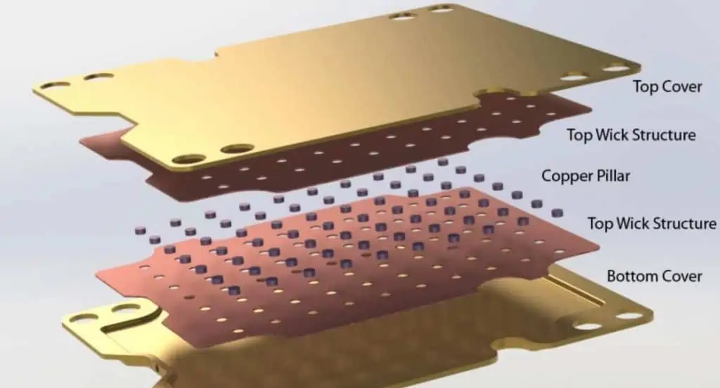
Material Layer Structure
| Layer | Material | Typical Thickness | Thermal Conductivity |
| Top Layer | Copper | 35-70μm | 398 W/m·K |
| Dielectric | Thermally Conductive | 75-150μm | 1-7 W/m·K |
| Base Layer | Aluminum | 0.8-3.0mm | 237 W/m·K |
| Surface Finish | HASL/ENIG | 3-15μm | Varies |
Thermal Properties Comparison
| Material Type | Thermal Conductivity (W/m·K) | Cost Factor | Weight Factor |
| FR-4 | 0.2-0.3 | 1 | 1 |
| Aluminum PCB | 1.0-7.0 | 2.0-3.0 | 1.5-2.0 |
| Ceramic PCB | 20-270 | 4.0-8.0 | 2.0-3.0 |
| Copper Core | 398 | 5.0-10.0 | 2.5-3.5 |
Heat Dissipation Mechanisms
Primary Heat Transfer Methods
| Method | Contribution | Efficiency Factor |
| Conduction | 60-70% | High |
| Convection | 20-30% | Medium |
| Radiation | 5-10% | Low |
Thermal Resistance Path
| Path Component | Typical Range (°C/W) | Optimization Method |
| Junction to Case | 0.5-3.0 | Die attach material |
| Case to Board | 1.0-5.0 | Thermal interface |
| Board to Ambient | 5.0-20.0 | Cooling solution |
Design Methodologies
Component Layout Guidelines
Thermal Spacing Requirements
| Component Power | Minimum Spacing | Recommended Spacing |
| <1W | 2mm | 5mm |
| 1-3W | 5mm | 10mm |
| 3-5W | 10mm | 15mm |
| >5W | 15mm | 20mm |
Copper Design Rules
| Feature | Specification | Purpose |
| Minimum Width | 0.2mm | Current capacity |
| Thermal Relief | 0.3mm | Assembly control |
| Thermal Via Diameter | 0.3-0.5mm | Heat transfer |
| Via Spacing | 1.0-1.5mm | Thermal distribution |
Thermal Design Considerations
Thermal Via Implementation
| Parameter | Value | Notes |
| Via Diameter | 0.3-0.5mm | Plated through-hole |
| Via Spacing | 1.0-1.5mm | Grid pattern |
| Plating Thickness | 25μm | Minimum |
| Fill Type | Solid/Paste | Application dependent |
Thermal Pattern Design
| Pattern Type | Thermal Efficiency | Cost Impact |
| Solid Plane | 100% | Baseline |
| Grid Pattern | 80-90% | -10% |
| Star Pattern | 70-80% | -20% |
| Custom Pattern | 60-95% | Varies |
Performance Optimization
Thermal Management Solutions
| Solution Type | Heat Dissipation | Cost Impact | Integration Complexity |
| Heat Sink | Up to 70% | Medium | Medium |
| Forced Air | Up to 85% | High | High |
| Thermal Paste | Up to 30% | Low | Low |
| Liquid Cooling | Up to 95% | Very High | Very High |
Material Selection Guidelines
| Component | Recommended Material | Thermal Conductivity | Cost Factor |
| Base Material | AL5052 | 138 W/m·K | 1 |
| Dielectric | High Tg Epoxy | 1.0-7.0 W/m·K | 1.5-3.0 |
| Thermal Interface | Silicone Based | 3.0-5.0 W/m·K | 2.0-4.0 |
| Surface Finish | ENIG | N/A | 1.5-2.0 |
Manufacturing Considerations
Process Parameters
| Process Step | Temperature Range | Time Duration | Critical Parameters |
| Preheating | 150-170°C | 60-90s | Ramp rate |
| Soldering | 230-250°C | 30-60s | Peak temperature |
| Cooling | 4°C/s max | N/A | Cooling rate |
Quality Control Methods
| Test Type | Method | Acceptance Criteria |
| Thermal Resistance | ASTM D5470 | ≤0.4°C/W |
| Dielectric Strength | ASTM D149 | ≥3kV |
| Thermal Cycling | -40 to +125°C | 1000 cycles |
| Thermal Shock | -65 to +150°C | 300 cycles |
Performance Evaluation
Thermal Testing Methods
| Test Method | Parameters Measured | Equipment Required |
| IR Scanning | Surface temperature | Thermal camera |
| Thermocouple | Point temperature | Data logger |
| Thermal Resistance | Overall performance | Thermal tester |
| CFD Analysis | Airflow patterns | Software |
Performance Metrics
| Metric | Target Range | Critical Factor |
| Junction Temperature | ≤125°C | Component reliability |
| Thermal Resistance | ≤0.4°C/W | Heat dissipation |
| Temperature Rise | ≤40°C | System performance |
| Temperature Uniformity | ±5°C | Thermal stress |
Frequently Asked Questions

Q1: What are the key advantages of using aluminum PCBs over traditional FR-4 boards?
A1: Aluminum PCBs offer several significant advantages:
- Superior thermal conductivity (1.0-7.0 W/m·K vs 0.2-0.3 W/m·K for FR-4)
- Better dimensional stability at high temperatures
- Enhanced reliability for high-power applications
- Reduced need for additional cooling solutions
- Longer lifespan of components due to better heat management
Q2: How can thermal via design be optimized for maximum heat dissipation?
A2: Optimal thermal via design involves several key considerations:
- Via diameter should be 0.3-0.5mm for best performance
- Grid pattern spacing of 1.0-1.5mm is recommended
- Copper plating thickness should be minimum 25μm
- Consider filled vias for better thermal conductivity
- Implement proper via pattern beneath high-power components
Q3: What are the critical factors in selecting dielectric materials for aluminum PCBs?
A3: Critical factors include:
- Thermal conductivity (higher is better)
- Dielectric strength (minimum 3kV)
- Glass transition temperature (Tg)
- Thermal expansion coefficient
- Cost considerations
- Manufacturing compatibility
Q4: How does component placement affect thermal performance?
A4: Component placement significantly impacts thermal performance through:
- Spacing between high-power components
- Proximity to board edges
- Air flow considerations
- Thermal interaction between components
- Access for additional cooling solutions
Q5: What are the common failure modes in aluminum PCBs and how can they be prevented?
A5: Common failure modes and prevention methods include:
- Delamination (use proper material selection and processing)
- Thermal stress (implement proper thermal relief design)
- Solder joint failure (use appropriate thermal profiles)
- Warpage (consider CTE matching in design)
- Dielectric breakdown (select appropriate dielectric material)
Conclusion
Aluminum PCB design for optimal heat dissipation requires careful consideration of material selection, layout design, and manufacturing processes. Success depends on understanding thermal management principles and implementing appropriate design methodologies. Regular testing and validation ensure that thermal performance meets design requirements. As power densities continue to increase, the importance of effective thermal management in aluminum PCBs will only grow.