
RAYPCB · ENGINEERING GUIDE
Machine Vision Robot Electronics: Connect Image Payload to a Timely Decision
Machine vision robot electronics carry information from a camera through transport and processing to a decision used by the machine. Image resolution is only one design input. The system must preserve timing, useful image quality and the meaning of the result under the actual lighting, motion and processing workload.
This page focuses on the camera-to-controller data path. The image worksheet calculates uncompressed active-pixel payload using the declared packing. It does not size an entire transport automatically, predict inference accuracy or certify a robot's behavior. Motion control and independently required protective functions remain separate responsibilities.
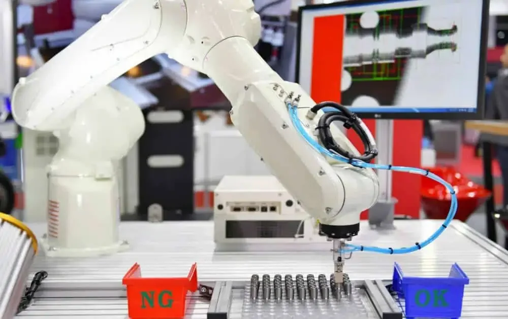
Define the visual decision before selecting the image format
State what the system needs to observe and what decision follows. Presence detection, position estimation and inspection of a small feature can demand different optics, illumination, exposure and processing. A higher pixel count does not automatically make the observation more useful.
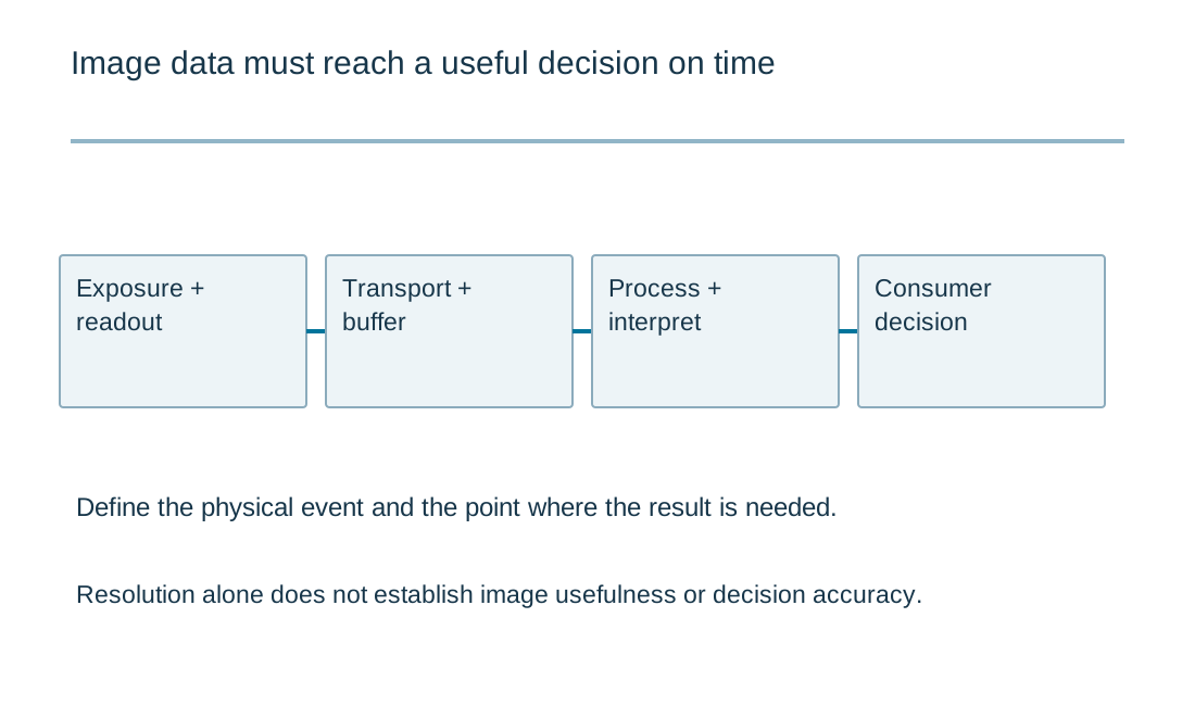
Identify the relevant motion and the time available for a decision. An image may be sharp and correctly processed but arrive too late for its intended use. Define the physical event and the point at which the receiving controller needs the result, then allocate the path between them.
Keep validation tied to representative conditions. Lighting changes, occlusion, product variation and camera placement can affect the result. Do not claim a detection accuracy from a few convenient demonstration images or present an illustrative PCB photograph as evidence of a deployed vision system.
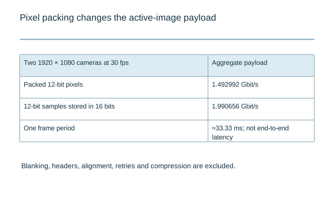
Calculate active-image payload with the actual packing
The worksheet multiplies active width, height and stored bits per pixel, then applies frame rate and camera count. For two 1920×1080 cameras at 30 frames/s with packed 12-bit pixels, each camera frame contains 3,110,400 active-image bytes. Aggregate payload is 186,624,000 bytes/s, or 1.492992 Gbit/s.
If each 12-bit sample is stored in a 16-bit word, enter 16 bits rather than 12. The same two-camera example then requires 1.990656 Gbit/s of active-image payload. Packing is an implementation detail with a real storage and transport consequence, not just a display label.
These values exclude blanking, transport headers, alignment, retransmission and other overhead. Compression requires an appropriate model for its actual behavior and is not silently assumed. A link's headline rate should not be compared with the lower-scope payload result as if that alone proved capacity.
| Review item | What to establish |
|---|---|
| Visual task | Feature/event, representative scene, motion and decision deadline. |
| Payload | Active dimensions, actual stored packing, frame rate and camera count. |
| Timing | Exposure-to-consumer boundaries, buffering and synchronization. |
| Channel | Exact devices, connector/cable, power and board transitions. |
| Validation | Independent labels, defined errors and reproducible hardware/software conditions. |
Uncompressed image payload budget
Uncompressed image payload budget
Use the current inputs and keep the assumptions
Load the example to see the units and record format, then clear it before entering your own revision. Example values are illustrative and do not select components or establish acceptance limits. Every field needs an intentional value; a blank number is not treated as zero. For CSV input, retain the header and put one item on each row. Quoted cells can contain commas, but duplicate headers and malformed rows are rejected.
Generate a result only after checking the measurement boundary, operating condition and units. Editing an input invalidates the old result and disables its download until you calculate again. An edited example stays labeled as an example. The report is created locally; it does not upload a design, send an enquiry or populate the Contact form. Attach it manually if it helps explain a requirement. You can contact RAYPCB without completing the tool.
| Input | What to establish before using it |
|---|---|
| Review reference | Use a nonconfidential revision label. |
| Image width · pixels | Integer active pixels; blanking excluded. |
| Image height · pixels | Integer active pixels. |
| Stored bits per pixel | Account for actual packing; use 16 if each 12-bit sample occupies a 16-bit word. |
| Frames per second | Actual capture rate. |
| Concurrent cameras | Integer; assumes identical streams. |
Separate frame period from end-to-end latency
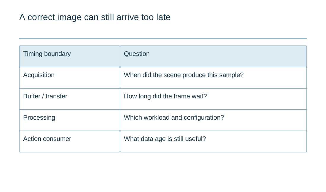
At 30 frames/s, one frame period is approximately 33.33 ms. That interval is not the time from a physical event to a machine action. Exposure, readout, buffering, transfer, processing, queueing and command handling can each contribute, and some can overlap depending on the implementation.
Define timestamps at meaningful boundaries. A capture timestamp and the time an application receives a buffer are different observations. Preserve synchronization and data-age assumptions when multiple cameras or another sensor contribute to the decision. A plausible average latency can conceal occasional queue growth.
The robot-arm electronics guide covers the separate feedback and motion-command boundary. Keep the perception result's age visible when it reaches that boundary. A correct coordinate without a defined time relationship can be unsuitable for the controller's intended task.
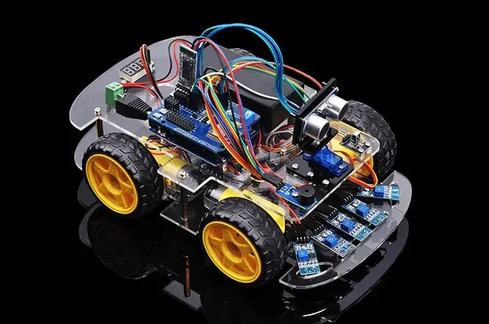
Review the camera link and PCB as a complete channel
Use the exact sensor, serializer or interface devices, cable and connector requirements. Analog Devices' robotic-vision discussion illustrates one link architecture; it is not a universal recommendation or a guarantee of performance for every camera arrangement. Compare the actual implementation against its required data and timing behavior.
Include board transitions, return paths, power and clocking in the review. A supported protocol name does not establish that a particular PCB and cable preserve the channel. Define test access carefully so the measurement arrangement does not create an unreviewed discontinuity.
For vehicle-related record transport, the CAN XL interface page addresses a different payload boundary. It should not be interpreted as an instruction to send raw camera streams over CAN XL. Choosing a transport begins with the actual information and its requirements.
Validate decisions with independently labeled observations
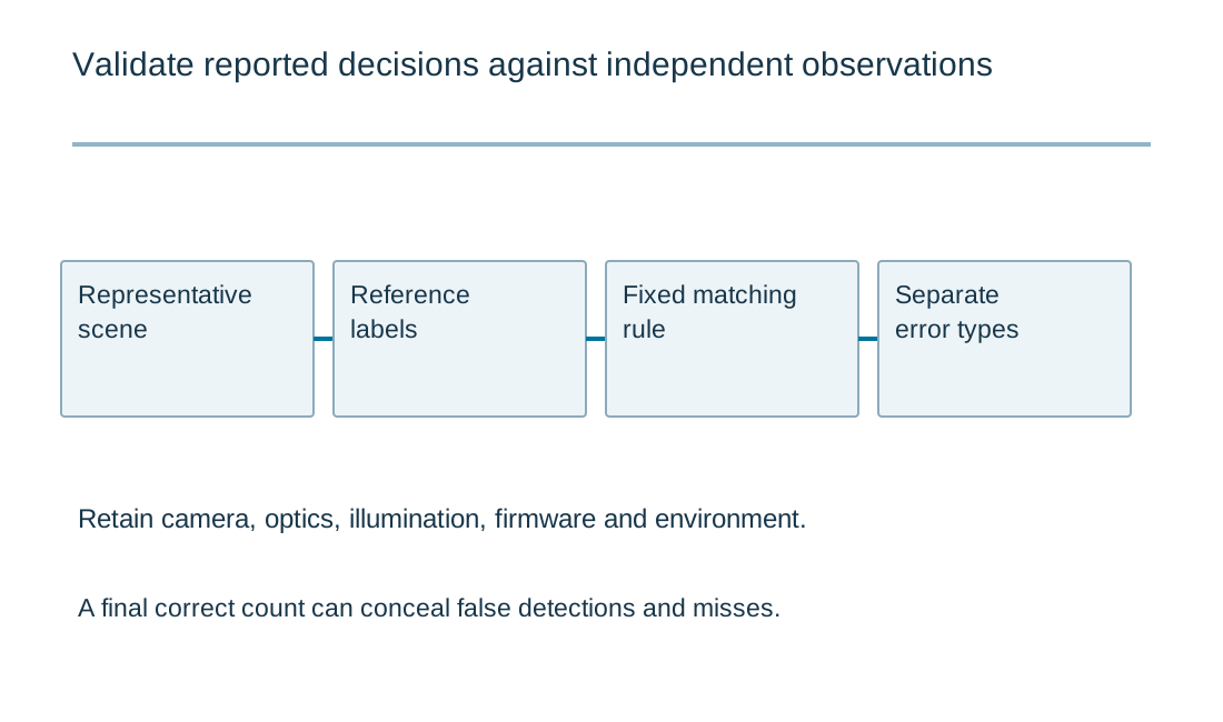
Define the event or condition being detected and the rule for matching reported results to reference observations. Separate false detections, missed events and timing errors where they matter. A correct total or a successful demonstration does not show which individual decisions were wrong.
The livestock-counting validation guide provides an example of why net counts can conceal errors. A vision product may need a different matching policy, but the principle is to keep error definitions and reference evidence explicit. Do not transfer an accuracy figure from one scene to another without supporting validation.
Record the camera configuration, optics, lighting, software and relevant environment with the test. Hardware or firmware changes can affect exposure, buffering and results even if the visual algorithm's name remains the same. Preserve a reproducible configuration for comparison.
Prepare the electronics build with an agreed observation path
Provide the board files, exact camera/link components, connector definitions, power requirements and software configuration needed for the agreed manufacturing test. State whether the fixture verifies electrical communication, a known image pattern or a defined application observation, and explain its coverage.
Keep complete-system vision validation with the responsible product process. PCB assembly inspection cannot establish detection accuracy, and a camera connection test cannot establish the timing of a robot action. The quotation should name the actual delivered object and evidence requested.
Send RAYPCB the current revision, quantity and the specific channel, assembly or test-access question. A payload report can clarify packing and rate assumptions. The useful outcome is a data path whose capacity and timing can be reviewed alongside the actual customer decision, without turning arithmetic into a performance claim.
Keep motion, perception and safety responsibilities visible
Map the signal from its physical origin to the action that uses it. For vision, this includes acquisition and processing; for motion, it includes feedback and drive behavior. Name the point where a timestamp is taken and the point where an output changes. Otherwise two plausible latency figures may describe different intervals.
Separate ordinary control performance from independently specified safety functions. An accurate encoder count or a correct image does not by itself establish safe machine behavior. Use the exact actuator, sensor and system documents to define the interface requirements and verification plan. Preserve wiring, grounding, mechanical loading and software revisions with measurements. A manufacturing discussion is strongest when it names the board's function, agreed test points and release evidence without implying that assembly inspection certifies an entire robot.
Standards, source context and limits
Use the exact device, system and material documents relevant to the released design. A public reference design demonstrates a particular implementation under its stated conditions; changing its parts, layout, enclosure or firmware creates a different verification task. Standards summaries here identify the type of evidence to request, not every clause of a licensed standard. Component qualification, board workmanship, product validation and regulatory acceptance are separate decisions.
For fabrication scope and the agreed construction requirements, see PCB manufacturing.