PCB simulation has become an indispensable tool in electronics development, serving as the bridge between theoretical design and reliable production. By enabling comprehensive virtual testing, simulation empowers engineers to achieve unprecedented levels of precision while dramatically accelerating development cycles – two crucial factors in today’s competitive electronics industry.
Through advanced simulation techniques, designers can:
- Identify and resolve potential signal integrity, power delivery, and thermal issues before prototyping
- Optimize board performance while still in the digital design phase
- Reduce physical prototyping iterations by up to 80%, according to industry studies
- Ensure compliance with stringent EMI/EMC requirements
What is PCB Simulation?

PCB simulation is a process that involves creating a virtual model of a printed circuit board and its components to analyze and predict its behavior under various conditions. This powerful technique allows engineers to test and optimize their designs before physical prototyping, saving time, resources, and ensuring higher quality end products.
PCB simulation utilizes advanced software tools that incorporate complex mathematical models and algorithms to accurately represent the electrical, thermal, and mechanical properties of a PCB. By simulating real-world conditions, designers can identify potential issues, optimize performance, and validate their designs with a high degree of confidence.
The primary goal of PCB simulation is to bridge the gap between theoretical design and practical implementation. It provides a virtual environment where engineers can experiment with different design options, component placements, and circuit configurations without the need for physical prototypes. This approach not only accelerates the design process but also significantly reduces the risk of errors and costly revisions in later stages of product development.
Read more about:
Types of Simulations Used in PCB Design
PCB simulation encompasses various types of analyses, each focusing on different aspects of the board’s performance. Let’s explore the most common types of simulations used in PCB design:
1. Signal Integrity Simulation
Signal integrity (SI) simulation is a critical aspect of PCB design, especially for high-speed digital circuits. This type of simulation focuses on analyzing the quality and behavior of electrical signals as they travel through the PCB.
Key aspects of signal integrity simulation include:
- Crosstalk analysis: Evaluating the interference between adjacent signal traces.
- Impedance matching: Ensuring proper impedance control throughout the signal path.
- Reflection analysis: Identifying and mitigating signal reflections that can cause distortions.
- Timing analysis: Verifying signal timing and synchronization in complex designs.
By performing signal integrity simulations, designers can optimize trace routing, layer stackup, and component placement to maintain signal quality and minimize issues like electromagnetic interference (EMI) and signal distortion.
2. Thermal Simulation
As electronic devices become more compact and powerful, managing heat dissipation becomes increasingly critical. Thermal simulation allows engineers to predict and analyze the heat distribution across a PCB during operation.
Thermal simulation helps in:
- Identifying hotspots: Locating areas of excessive heat generation on the board.
- Optimizing component placement: Arranging components to ensure efficient heat dissipation.
- Evaluating cooling solutions: Testing the effectiveness of heat sinks, fans, and other cooling mechanisms.
- Predicting thermal stress: Analyzing the impact of temperature changes on board materials and components.
By conducting thermal simulations, designers can ensure that their PCBs operate within safe temperature ranges, preventing thermal-related failures and improving overall reliability.
3. Power Integrity Simulation
Power integrity (PI) simulation focuses on analyzing the power distribution network (PDN) of a PCB. This type of simulation is crucial for ensuring that all components receive stable and clean power supply throughout the board.
Power integrity simulation addresses:
- Voltage drop analysis: Identifying areas where voltage levels may drop below acceptable thresholds.
- Decoupling capacitor optimization: Determining the optimal placement and values of decoupling capacitors.
- Current density analysis: Ensuring that traces and planes can handle the required current without overheating.
- Resonance analysis: Identifying and mitigating potential resonance issues in the power distribution network.
By optimizing power integrity, designers can prevent issues like ground bounce, power supply noise, and electromagnetic interference, all of which can significantly impact the performance and reliability of the PCB.
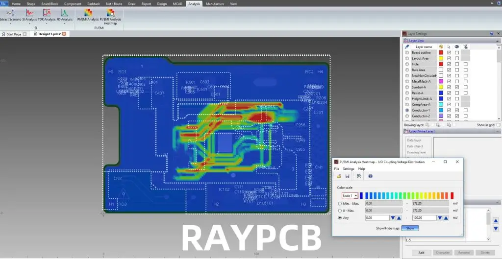
4. Electromagnetic Compatibility (EMC) Simulation
Electromagnetic Compatibility (EMC) simulation is essential for ensuring that a PCB design complies with regulatory standards and operates correctly in its intended electromagnetic environment.
EMC simulation helps in:
- EMI analysis: Predicting and mitigating electromagnetic interference generated by the PCB.
- Susceptibility testing: Evaluating the board’s resistance to external electromagnetic disturbances.
- Shielding effectiveness: Assessing the performance of EMI shielding techniques.
- Antenna performance: Analyzing the behavior of intentional radiators like antennas in wireless devices.
By conducting EMC simulations, designers can identify potential compliance issues early in the design process, reducing the risk of failing regulatory tests and minimizing the need for costly redesigns.
Benefits of PCB Simulation

The adoption of PCB simulation in the design process offers numerous advantages that significantly impact the quality, efficiency, and cost-effectiveness of PCB production. Let’s explore these benefits in detail:
1. Cost Savings
One of the most significant advantages of PCB simulation is its ability to reduce overall development costs. By identifying and resolving issues in the virtual environment, designers can minimize the number of physical prototypes required. This reduction in prototyping iterations leads to:
- Lower material costs: Fewer prototype boards and components need to be manufactured.
- Reduced testing expenses: Less time and resources spent on physical testing of multiple iterations.
- Minimized rework costs: Early detection of issues prevents expensive modifications in later stages.
2. Time Efficiency
PCB simulation dramatically accelerates the design process by allowing engineers to test and validate their designs quickly. This time-saving aspect manifests in several ways:
- Rapid design iterations: Changes can be implemented and tested in minutes rather than days or weeks.
- Parallel development: Different aspects of the design can be simulated simultaneously by team members.
- Faster time-to-market: Reduced development cycles lead to quicker product launches.
3. Error Detection and Debugging
Simulation tools provide a comprehensive view of the PCB’s behavior, making it easier to identify and resolve potential issues:
- Early problem detection: Issues are caught before physical prototyping, saving time and resources.
- Root cause analysis: Simulation data helps in pinpointing the exact causes of problems.
- Virtual troubleshooting: Designers can experiment with different solutions in a risk-free environment.
4. Performance Optimization
PCB simulation allows designers to fine-tune their designs for optimal performance:
- Component optimization: Ideal component values and placements can be determined through simulation.
- Layout refinement: Trace routing and layer stackup can be optimized for best signal integrity and EMC performance.
- Power distribution optimization: Simulation helps in creating efficient and stable power delivery networks.
5. Reliability Improvement
By simulating various operating conditions and stress scenarios, designers can enhance the overall reliability of their PCBs:
- Stress testing: Simulating extreme conditions helps in identifying potential failure points.
- Longevity prediction: Thermal and power simulations can estimate the lifespan of components and the board.
- Quality assurance: Comprehensive simulations reduce the likelihood of field failures.
6. Enhanced Collaboration
PCB simulation tools often come with collaboration features that improve team communication and productivity:
- Shared simulation results: Team members can easily access and review simulation data.
- Version control: Changes and improvements can be tracked and managed efficiently.
- Remote collaboration: Simulation data can be shared and discussed across different locations.
7. Compliance Verification
Simulation helps in ensuring that PCB designs meet industry standards and regulatory requirements:
- EMC compliance: EMC simulations help in meeting electromagnetic compatibility standards.
- Safety standards: Thermal and power simulations assist in adhering to safety regulations.
- Industry-specific requirements: Simulations can be tailored to meet specific industry standards (e.g., automotive, aerospace).
8. 3D Visualization and Analysis
Modern PCB simulation tools offer powerful 3D visualization capabilities:
- Spatial analysis: Designers can evaluate component placement and board layout in three dimensions.
- Interference checking: 3D models help in identifying potential mechanical conflicts.
- Aesthetic considerations: Visual representation aids in designing visually appealing products.
9. Improved Decision-Making
Simulation data provides a solid foundation for making informed design decisions:
- Data-driven choices: Decisions are based on quantitative simulation results rather than guesswork.
- Trade-off analysis: Designers can evaluate the impact of different design choices on overall performance.
- Risk assessment: Potential issues can be quantified and prioritized based on simulation outcomes.
10. Integration with Manufacturing Processes
PCB simulation can be integrated with manufacturing processes to ensure smoother production:
- DFM (Design for Manufacturing) optimization: Simulation helps in creating designs that are easier to manufacture.
- Yield improvement: By identifying potential manufacturing issues early, designers can improve production yield.
- Process simulation: Some tools allow simulation of manufacturing processes to predict and prevent production issues.
How to Simulate a PCB Design

Simulating a PCB design involves several steps and requires the use of specialized software tools. Here’s a general overview of the process:
1. Prepare the Design Data
Before simulation can begin, you need to have a complete PCB design, including:
- Schematic diagram
- PCB layout
- Component models (including parasitic elements)
- Material properties of the board and components
2. Choose the Appropriate Simulation Type
Based on your design goals and concerns, select the type of simulation you want to perform:
- Signal integrity
- Power integrity
- Thermal analysis
- EMC simulation
3. Set Up the Simulation Environment
Configure the simulation software with the necessary parameters:
- Import your PCB design data
- Define simulation boundaries and conditions
- Set up excitation sources and loads
- Specify frequency ranges or time domains for analysis
4. Run the Simulation
Execute the simulation and wait for the results. Depending on the complexity of your design and the type of simulation, this process can take anywhere from a few minutes to several hours.
5. Analyze the Results
Once the simulation is complete, carefully examine the output data:
- Review waveforms, graphs, and 3D visualizations
- Look for any violations of design rules or performance thresholds
- Identify areas that require optimization or further investigation
6. Iterate and Optimize
Based on the simulation results:
- Make necessary changes to your design
- Re-run simulations to verify improvements
- Repeat the process until desired performance is achieved
7. Document and Report
Create comprehensive reports documenting the simulation process, results, and any design changes made. This documentation is valuable for team collaboration, design reviews, and future reference.
Can I Do PCB Simulation Online?
Yes, it is possible to perform PCB simulation online through various cloud-based platforms and services. Online PCB simulation offers several advantages:
- Accessibility: You can access simulation tools from any device with an internet connection.
- Reduced hardware requirements: Heavy computations are performed on remote servers, reducing the need for powerful local hardware.
- Automatic updates: Cloud-based tools are typically updated automatically, ensuring you always have the latest features and models.
- Collaboration: Online platforms often provide better tools for team collaboration and sharing of results.
However, there are also some considerations to keep in mind:
- Internet dependency: A stable internet connection is crucial for uninterrupted simulation.
- Data security: Ensure that the online platform you choose has adequate security measures to protect your design data.
- Subscription costs: Many online simulation tools require ongoing subscription fees.
- Limited customization: Some online tools may offer fewer customization options compared to traditional desktop software.
Some popular online PCB simulation platforms include:
- Altium 365
- EDA Board
- CircuitMaker
- PCBWeb
- Upverter
When choosing an online PCB simulation tool, consider factors such as the types of simulations offered, ease of use, integration with your existing design workflow, and pricing structure.
Best 5 PCB Simulation Software
While there are numerous PCB simulation tools available in the market, some stand out for their comprehensive features, accuracy, and user-friendliness. Here are five of the best PCB simulation software options:
1. ANSYS SIwave
ANSYS SIwave is a powerful electromagnetic simulation tool specifically designed for PCB and IC package analysis. It excels in:
- Signal integrity analysis
- Power integrity simulation
- EMI/EMC prediction
- 3D full-wave electromagnetic field solving
Pros:
- Highly accurate simulations
- Seamless integration with other ANSYS tools
- Supports complex, multi-layer designs
Cons:
- Steep learning curve
- Relatively high cost
2. Cadence Sigrity
Cadence Sigrity offers a suite of analysis tools for PCB and IC package design, including:
- Signal integrity analysis
- Power integrity simulation
- Thermal analysis
- EMI/EMC simulation
Pros:
- Comprehensive simulation capabilities
- Good integration with Cadence PCB design tools
- Supports advanced technologies like DDR4 and PCIe
Cons:
- Can be resource-intensive for complex simulations
- Requires significant expertise for optimal use
3. Keysight ADS (Advanced Design System)
Keysight ADS is a comprehensive electronic design automation software that includes powerful PCB simulation capabilities:
- EM simulation
- Signal integrity analysis
- Power integrity simulation
- Thermal analysis
Pros:
- Wide range of simulation types in one package
- Excellent for RF and microwave designs
- Strong support for high-speed digital design
Cons:
- Complex user interface
- High initial learning curve
4. Mentor HyperLynx
Mentor HyperLynx, now part of Siemens Digital Industries Software, offers a suite of easy-to-use yet powerful PCB simulation tools:
- Signal integrity analysis
- Power integrity simulation
- EMC analysis
- Thermal simulation
Pros:
- User-friendly interface
- Fast simulation times
- Good balance of ease-of-use and advanced features
Cons:
- May lack some advanced features found in more specialized tools
- Limited customization options for some analyses
5. PADS Professional
PADS Professional, also part of the Mentor Graphics (Siemens) family, provides integrated PCB design and analysis capabilities:
- Signal integrity simulation
- Power integrity analysis
- Thermal analysis
- EMI/EMC simulation
Pros:
- Integrated design and simulation environment
- Scalable solution suitable for individual engineers to large teams
- Good price-to-performance ratio
Cons:
- Some advanced features may require additional modules
- Less specialized than some dedicated simulation tools
When choosing PCB simulation software, consider factors such as:
- Types of simulations required for your designs
- Integration with your existing PCB design tools
- Available computing resources
- Budget constraints
- Team expertise and training requirements
It’s often beneficial to trial multiple software options to find the one that best fits your specific needs and workflow.
The Traditional PCB Design Process vs. a Process Integrated with Simulation
The integration of simulation into the PCB design process has significantly transformed the way electronic products are developed. Let’s compare the traditional PCB design process with a modern approach that incorporates simulation at various stages:
Traditional PCB Design Process
- Conceptualization: Define product requirements and create initial schematics.
- Schematic Design: Develop detailed circuit schematics.
- Component Selection: Choose appropriate components based on specifications.
- PCB Layout: Create the physical layout of the board.
- Design Rule Check (DRC): Verify that the layout meets basic design rules.
- Prototype Manufacturing: Produce a physical prototype of the PCB.
- Testing and Debugging: Physically test the prototype and identify issues.
- Revisions: Make necessary changes based on test results.
- Final Production: Once satisfactory results are achieved, move to full production.
PCB Design Process Integrated with Simulation
- Conceptualization: Define product requirements and create initial schematics.
- Schematic Design: Develop detailed circuit schematics.
- Initial Simulation: Perform basic simulations to verify circuit behavior.
- Component Selection: Choose components based on simulation results and specifications.
- PCB Layout: Create the physical layout of the board.
- Comprehensive Simulation:
- Signal integrity simulation
- Power integrity simulation
- Thermal analysis
- EMC simulation
- Design Optimization: Refine the design based on simulation results.
- Design Rule Check (DRC): Verify that the layout meets design rules and simulation-derived constraints.
- Virtual Prototyping: Create and analyze a complete virtual model of the PCB.
- Design Review: Conduct a thorough review based on simulation results and virtual prototype performance.
- Physical Prototype Manufacturing: Produce a physical prototype with high confidence in its performance.
- Validation Testing: Conduct physical tests to confirm simulation predictions and overall performance.
- Final Adjustments: Make minor tweaks if necessary, based on validation results.
- Production: Move to full-scale production with a highly optimized and verified design.
Key Differences and Advantages of Simulation-Integrated Process
- Early Problem Detection: Simulation allows issues to be identified and resolved much earlier in the design cycle, reducing costly late-stage changes.
- Reduced Prototyping Iterations: By catching and fixing issues virtually, fewer physical prototypes are needed, saving time and resources.
- Optimized Designs: Simulation enables designers to fine-tune their designs for optimal performance before physical production.
- Increased Confidence: Engineers have a much higher level of confidence in their designs before moving to production.
- Faster Time-to-Market: The overall design process can be significantly accelerated by reducing physical prototyping and testing cycles.
- Cost Efficiency: While there may be an initial investment in simulation tools, the long-term savings in prototyping and redesign costs are substantial.
- Enhanced Collaboration: Simulation results provide concrete data for team discussions and decision-making.
- Improved Documentation: Simulation processes and results contribute to more comprehensive design documentation.
By integrating simulation throughout the PCB design process, engineers can create more reliable, high-performance designs while saving time and resources.
Difference Between PCB Simulation and Reality Boards
While PCB simulation has become an indispensable tool in the design process, it’s important to understand its relationship with physical, real-world boards. Let’s explore the key differences and considerations:
1. Idealized vs. Real-World Conditions
- Simulation: Uses idealized models and controlled conditions. Can simulate perfect scenarios that may not exist in reality.
- Reality: Subject to real-world variations, imperfections, and environmental factors not always accounted for in simulations.
2. Component Tolerances
- Simulation: Often uses nominal values for components, though advanced simulations can incorporate tolerance ranges.
- Reality: Actual components have manufacturing tolerances that can affect circuit behavior.
3. Environmental Factors
- Simulation: Can model specific environmental conditions, but may not capture all real-world variables.
- Reality: Exposed to varying temperatures, humidity, electromagnetic interference, and other environmental factors.
4. Manufacturing Variations
- Simulation: Typically assumes perfect manufacturing processes.
- Reality: Subject to variations in PCB fabrication, such as etching tolerances, material inconsistencies, etc.
5. Aging and Wear
- Simulation: Generally models new components and materials.
- Reality: Components and materials degrade over time, affecting long-term performance.
6. Unexpected Interactions
- Simulation: Based on known models and interactions.
- Reality: May exhibit unexpected behaviors due to unforeseen interactions between components or external factors.
7. Simulation Accuracy vs. Computation Time
- Simulation: More accurate simulations often require longer computation times, leading to trade-offs between accuracy and speed.
- Reality: Real-world performance is instantaneous but may require extensive testing to fully characterize.
8. Cost and Time Investment
- Simulation: Requires upfront investment in software and training but allows for rapid iterations.
- Reality: Physical prototyping can be more expensive and time-consuming but provides definitive real-world results.
Bridging the Gap
To maximize the benefits of simulation while ensuring real-world performance, consider the following approaches:
- Correlation Studies: Regularly compare simulation results with measurements from physical prototypes to improve simulation accuracy.
- Design Margins: Include safety margins in designs to account for real-world variations not captured in simulations.
- Statistical Analysis: Use Monte Carlo simulations to account for component tolerances and manufacturing variations.
- Hybrid Approach: Combine simulation with targeted physical testing for critical aspects of the design.
- Continuous Learning: Use discrepancies between simulated and real results to refine simulation models and techniques.
- Advanced Modeling: Incorporate more sophisticated models that account for non-ideal behaviors, parasitics, and environmental factors.
- Post-Production Validation: Conduct thorough testing on production boards to verify that real-world performance aligns with simulation predictions.
Conclusion
PCB simulation has revolutionized the electronic design process, offering numerous benefits including cost savings, time efficiency, and performance optimization. By bridging the gap between virtual designs and physical realities, simulation tools enable engineers to create more reliable, high-performance PCBs with greater confidence.
While differences between simulated and real-world results will always exist, the continuous advancement of simulation technologies is narrowing this gap. By understanding the strengths and limitations of PCB simulation, designers can leverage these powerful tools effectively, complementing them with appropriate physical testing and validation.
As the complexity of electronic designs continues to increase, the role of PCB simulation in ensuring product quality, reliability, and time-to-market advantages will only grow. Embracing and mastering these simulation techniques is crucial for staying competitive in the rapidly evolving field of electronic design.
By integrating PCB simulation into their workflow, designers and engineers can push the boundaries of what’s possible in electronic design, creating innovative products that meet the demanding requirements of today’s technology-driven world.