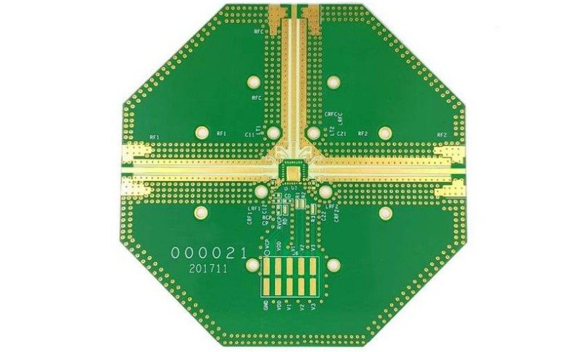
The Complete Guide to Rogers PCB: Materials, Applications, and Design Considerations

RayMing brings over two decades of specialized experience in Rogers PCB manufacturing, delivering complete solutions across the full Rogers portfolio—from RO4350B and RO4003C to RO3003, RT5880, RT5870, AD, and TMM series.

Introduction

Rogers PCB materials have revolutionized high-frequency electronic design, providing engineers with the precision and reliability needed for today’s most demanding applications. From 5G telecommunications infrastructure to aerospace radar systems, Rogers printed circuit boards deliver superior performance where standard FR4 materials fall short.

This comprehensive guide covers everything you need to know about Rogers PCB materials, from basic principles to advanced design considerations, helping you make informed decisions for your next high-frequency project.

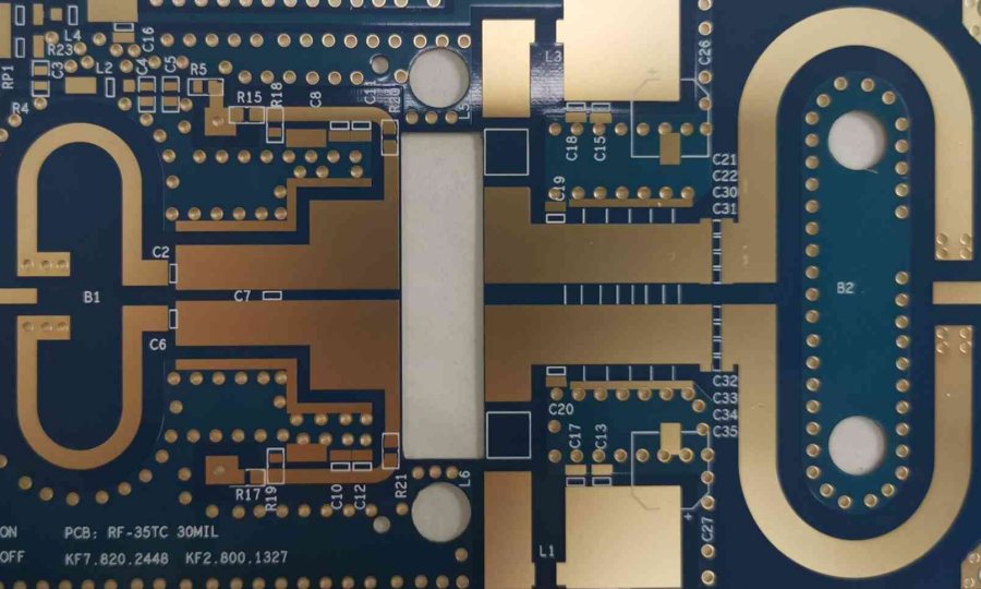
What is Rogers PCB?

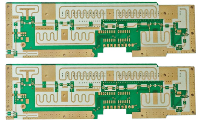
Rogers PCB is a type of high-performance printed circuit board substrate material that is made by laminating multiple layers of specialized materials together. The material is named after the Rogers Corporation, which is a leading manufacturer of high-performance engineered materials.

Unlike traditional FR4 boards, Rogers PCBs utilize advanced dielectric materials specifically engineered for high-frequency applications. These materials typically feature ceramic-filled composites, hydrocarbon resins, or PTFE (polytetrafluoroethylene) bases that provide exceptional electrical properties at frequencies ranging from MHz to GHz levels.

Key Characteristics of Rogers PCB Materials

Rogers PCBs distinguish themselves through several critical properties:

Low Dielectric Constant (Dk): Rogers PCB materials have a low dielectric constant, typically between 2.2 and 3.5, which means that they can maintain signal integrity and minimize signal loss at high frequencies and over long distances.

Minimal Loss Tangent (Df): Rogers PCB materials have a low loss tangent, typically between 0.001 and 0.002, which means that they can minimize signal attenuation and distortion.

Superior Thermal Management: Rogers PCB materials have a high thermal conductivity, typically between 0.5 and 2 W/mK, which means that they can effectively dissipate heat and maintain stable performance even at high temperatures.

Dimensional Stability: Rogers PCB materials have a low coefficient of thermal expansion (CTE), typically between 10 and 17 ppm/°C, which means that they are less likely to warp or deform under temperature changes.

Rogers PCB vs FR4: A Comprehensive Comparison

fr4 material vs rogers material

Understanding the differences between Rogers and FR4 materials is crucial for proper material selection. Here’s a detailed comparison across key parameters:

Cost Considerations

FR4 material is the most cost-effective type available for circuit board fabrication. They are lightweight, moisture-resistant, and have high dielectric strength. Rogers materials command a premium price due to their specialized composition and manufacturing processes.

When to Choose FR4:

  • Budget-constrained projects
  • Low to medium frequency applications (under 500 MHz)
  • Standard operating temperatures
  • Consumer electronics applications

When to Choose Rogers:

  • High-frequency applications (above 500 MHz)
  • Critical signal integrity requirements
  • Extreme operating conditions
  • Aerospace, defense, and telecommunications applications

Frequency Performance

FR4 PCBs perform well only up to a certain range of frequencies, while the Rogers materials perform superbly over a much larger frequency range. That is why Rogers PCB materials are mostly in demand for high-frequency applications extending beyond 500 MHz. In contrast, FR4 PCBs can just about reach 10 MHz.

Thermal Management

FR4 PCB materials have a thermal conductivity nearing 0.3 W/mK. In comparison, the Rogers PCB materials have a thermal conductivity ranging from 0.5 to 0.95 W/mK. Therefore, Rogers materials can conduct heat much faster as compared to FR4 materials, and that helps to make thermal management easier in PCB manufacturing and assembly.

Moisture Absorption

PCB board materials typically absorb moisture between 0.1 and 0.2 percent from the ambient. Moisture absorption directly affects the electrical and thermal properties of the material. For instance, with higher moisture absorption, the performance and efficiency of the material goes down. On the other hand, Rogers PCB materials have a very low value of moisture absorption, ranging from 0.02 to 0.08 percent.

Impedance Stability

The dielectric constant of FR4 is approximately 4.5. In comparison, the value for Rogers PCB materials ranges from 2.5 to 11. Therefore, Rogers PCB materials have much higher impedance stability.

Rogers PCB Material Series: A Complete Overview

Rogers Corporation offers several distinct material series, each optimized for specific applications and performance requirements.

RO4000® Series: The Industry Standard

RO4000 Series materials are high frequency circuit boards with glass reinforced hydrocarbon and ceramic laminates. This series represents the most popular choice for high-frequency applications due to its excellent balance of performance and processability.

Key Materials in RO4000 Series:

RO4003C: RO4003C materials are proprietary woven glass reinforced hydrocarbon/ceramics with the electrical performance of PTFE/woven glass and the manufacturability of epoxy/ glass. This material offers:

  • Dielectric constant (Dk): 3.38
  • Low loss tangent
  • Cost-effective solution for RF applications
  • Compatible with standard PCB processing

RO4350B: RO4350B – Dielectric constant is 3.48, Thermal conductivity is higher, Good thermal & power management. Features include:

  • UL 94 V-0 flame rating
  • Enhanced thermal properties
  • Excellent for high-power RF designs
  • Superior dimensional stability

RO4360: Designed for applications requiring high thermal conductivity while maintaining excellent electrical properties.

RO4835: Optimized for high-frequency applications with exceptional loss characteristics.

RO3000® Series: Ceramic-Filled PTFE Excellence

Rogers RO3000 high-frequency base materials are ceramic-filled PTFE composites designed for use in commercial microwave and RF applications. This advanced laminate family offers exceptional electrical and mechanical stability. They have the lowest loss tangent (Df) among Rogers laminates.

Notable RO3000 Materials:

RO3003:

  • Dielectric constant: 3.0
  • Insertion loss is very low for high-frequency applications up to 10GHz.
  • Excellent for microwave applications

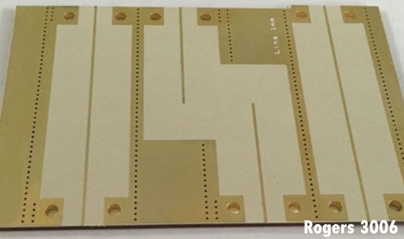
RO3006:

  • Dielectric constant: 6.15
  • It is best for amplifier applications.

RO3010:

  • Dielectric constant: 10.2
  • The cost is low.

RT/duroid® Series: Aerospace and Defense Grade

Rogers RT/duroid is a material especially for high-frequency circuits which is filled by PTFE laminates. Best for durability and reliability, Uses: Aerospace and defense.

Key RT/duroid Materials:

RT/duroid 5880:

  • Density – Very low. Dielectric constant- 2.2. Applications- mmWave Antennas.

RT/duroid 6002:

  • Cost-effective PTFE. It has better thermal conductivity than FR4.

RT/duroid 6202:

  • Dielectric constant is 2.94, which is stable. It Works up to GHz. Low electrical loss. Moisture absorption is low.

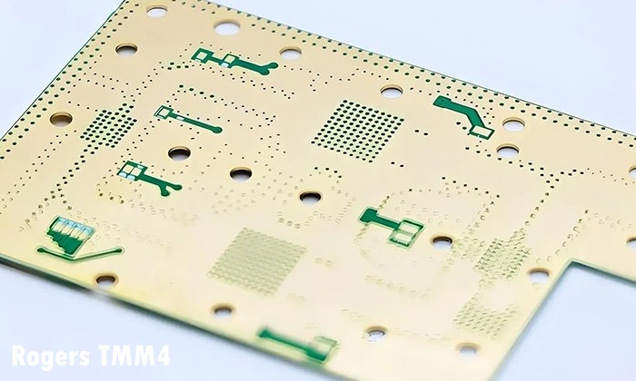
TMM® Series: Thermoset Microwave Materials

The TMM series offers exceptional thermal and mechanical stability for the most demanding applications. These materials feature:

  • High thermal conductivity
  • Low dielectric loss
  • Excellent dimensional stability
  • Superior performance under extreme conditions

Applications of Rogers PCB Materials

Rogers PCBs enable advanced functionality across numerous high-tech industries:

Telecommunications and 5G Infrastructure

Rogers offers a diverse range of antenna-grade circuit laminates to fulfill the stringent requirements of military antenna systems and modern automobile radar systems. These materials are engineered for excellent reliability and consistent performance with minimal circuit losses at high frequencies.

5G Applications:

  • mmWave antenna arrays
  • Base station power amplifiers
  • Beamforming networks
  • High-speed backhaul systems

Aerospace and Defense

Circuit boards that are used in the avionics sector should be able to tolerate extreme temperature swings, shock, vibrations, and pressure changes. The excellent thermal properties of Rogers make them ideal for avionics equipment.

Aerospace Applications:

  • Radar systems
  • Satellite communication equipment
  • Navigation systems
  • Electronic warfare systems
  • Avionics control systems

Automotive Electronics

Modern vehicles increasingly rely on high-frequency electronics:

  • Automotive radar systems (77 GHz)
  • Advanced driver assistance systems (ADAS)
  • Vehicle-to-everything (V2X) communication
  • Collision avoidance sensors

Medical Equipment

Rogers materials enable precision medical devices:

  • MRI systems
  • Medical imaging equipment
  • Diagnostic instruments
  • Therapeutic devices

Test and Measurement

High-precision instrumentation requires Rogers materials for:

  • Network analyzers
  • Signal generators
  • Spectrum analyzers
  • Calibration standards

Rogers PCB Manufacturing Considerations

Manufacturing Rogers PCBs requires specialized knowledge and techniques to achieve optimal results.

Surface Preparation

A chemical process consisting of cleaning, micro-etching, water rinsing, and drying is the preferred method of surface preparation, especially for thinner core materials. Mechanical scrubbing should only be considered for the cores that are thicker than 60 mils.

Multi-layer Bonding

Rogers cores can be prepared for multi-layer bonding using any oxide or oxide alternative process that is also used for high Tg FR4 material systems. Inner-layer cores should be baked in a rack for 30 minutes at 107°C to 121°C (225F to 250F) prior to layup.

Drilling Considerations

Drilling vias/holes using CO2, UV or CO2/UV combination lasers are preferred when aspect ratios permit. A post-laser clean with alkaline permanganate or CF4/O2 plasma can be used to ensure a good electrical connection to copper pads at the base of vias.

Copper Plating and Processing

Panel and pattern processing using electrolytic tin plating and acid copper is compatible with Rogers. The materials can then be treated using any standard strip/etch/strip (SES) method after plating.

Solder Mask Application

After etching, surfaces should bond very well to direct screened and photo-imageable solder masks. A short bake for 30-60 minutes at 110°C to 125°C may be required to ensure the board surfaces are dry prior to applying the solder mask.

Rogers PCB Material Selection Guide

Choosing the right Rogers material requires careful consideration of multiple factors:

Operating Frequency Requirements

Low to Mid-Range (500 MHz – 5 GHz):

  • RO4003C: Cost-effective option
  • RO4350B: When flame retardancy is required

High Frequency (5 – 20 GHz):

  • RO3003: Excellent for microwave applications
  • RO4835: Low-loss performance

mmWave (20+ GHz):

  • RT/duroid 5880: Ultra-low loss
  • RO3003: Proven millimeter-wave performance

Dielectric Constant Selection

For high frequency application less dielectric constant required. So, Roger material has best choice in that case. Less dielectric means high capacitance and lower impedance. Due to this we get best impedance matching.

Applications by Dk Range:

  • Dk 2.2-3.0: Ultra-wideband applications, mmWave antennas
  • Dk 3.0-4.0: Most RF/microwave circuits, 5G systems
  • Dk 6.0-10.0: Size-constrained designs, filter applications

Thermal Considerations

When the temp goes up to beyond level then material gets expand for this case Rogers is far better than other materials.

High-Power Applications:

  • Consider thermal conductivity (k value)
  • Evaluate glass transition temperature (Tg)
  • Assess coefficient of thermal expansion (CTE)

Environmental Requirements

Space Applications:

  • Low outgassing materials
  • Radiation resistance
  • Extreme temperature cycling

Military/Defense:

  • Wide temperature range operation
  • Shock and vibration resistance
  • Long-term reliability

Cost Optimization Strategies for Rogers PCB

While Rogers materials are more expensive than FR4, several strategies can optimize costs:

Hybrid Constructions

Rogers PCB layers may be combined with FR4 layers to achieve improved performance to minimum cost vs. all layers being Rogers materials. When this is done, the signals need to be put on a Rogers PCB core and not on prepreg.

Hybrid Design Benefits:

  • Reduced material costs
  • Maintained signal integrity for critical layers
  • Standard processing for non-critical layers

Material Thickness Optimization

  • Use thinner Rogers cores where possible
  • Optimize stackup design for minimum Rogers content
  • Consider embedded component technologies

Volume Considerations

  • Leverage bulk purchasing for material savings
  • Consider panel utilization optimization
  • Evaluate long-term supply agreements

Design Guidelines for Rogers PCB

Successful Rogers PCB design requires attention to specific considerations:

Stackup Design

Key Principles:

  • Place high-frequency signals on Rogers layers
  • Use Rogers cores for controlled impedance
  • Consider symmetric stackups for warpage control

Via Design

  • Minimize via stubs in high-frequency signals
  • Use blind/buried vias when appropriate
  • Consider back-drilling for critical signals

Thermal Management

  • Include thermal vias for heat dissipation
  • Design adequate copper pour for heat spreading
  • Consider component placement for thermal efficiency

Signal Integrity

  • Maintain consistent trace geometries
  • Use proper ground plane design
  • Implement appropriate spacing rules

Quality Control and Testing

Rogers PCB quality requires specialized testing approaches:

Electrical Testing

  • Time Domain Reflectometry (TDR)
  • Vector Network Analysis (VNA)
  • S-parameter measurements
  • Insertion loss verification

Material Verification

  • Dielectric constant measurement
  • Loss tangent validation
  • Thermal property testing
  • Dimensional stability assessment

Reliability Testing

  • Thermal cycling
  • Moisture resistance
  • Mechanical stress testing
  • Long-term stability evaluation

Future Trends in Rogers PCB Technology

The Rogers PCB industry continues evolving with emerging technologies:

Advanced 5G and 6G

Next-generation wireless systems demand:

  • Higher frequency operation (sub-THz)
  • Lower loss materials
  • Improved thermal management
  • Enhanced integration capabilities

Automotive Radar Evolution

Automotive applications are driving:

  • 77/79 GHz radar optimization
  • Integration with silicon technologies
  • Cost reduction initiatives
  • Higher volume manufacturing

Space and Satellite Communications

Growing satellite constellations require:

  • Improved radiation resistance
  • Lower outgassing materials
  • Enhanced reliability
  • Miniaturization capabilities

Conclusion

Rogers PCB materials represent the pinnacle of high-frequency circuit board technology, enabling applications from 5G infrastructure to space exploration. While these materials command premium pricing, their superior electrical properties, thermal performance, and reliability make them indispensable for demanding applications.

Success with Rogers PCBs requires understanding material properties, proper design techniques, and specialized manufacturing considerations. By following the guidelines in this comprehensive guide, engineers can harness the full potential of Rogers materials to create cutting-edge electronic systems.

Whether you’re designing next-generation telecommunications equipment, aerospace systems, or automotive radar, Rogers PCB materials provide the foundation for reliable, high-performance solutions. As technology continues advancing toward higher frequencies and more demanding applications, Rogers materials will remain at the forefront of electronic innovation.

The investment in Rogers PCB technology pays dividends through improved system performance, enhanced reliability, and the ability to push the boundaries of what’s possible in high-frequency electronic design.