Printed circuit boards (PCBs) provide the interconnect foundation of electronics. But PCBs aren’t designed in isolation. They must interface with other components and assemblies to fully create products. An important part of enabling these mechanical connections is PCB rivets.
PCB rivets provide a robust method to attach a circuit board to chassis, enclosures, heat sinks and more. This article provides comprehensive guidance on PCB rivet usage including:
- Rivet types and materials
- Design considerations
- Installation processes
- Inspection techniques
- Advantages over screws
- Frequently asked questions
By covering key riveting concepts and best practices, readers will gain the knowledge to implement riveted connections that offer superior reliability and longevity.
Rivet Types for PCBs

There are two primary varieties of rivets used with printed circuit boards:
Blind Rivets
These are tubular rivets that get installed through a hole in the PCB and mating component. A blind rivet tool pulls a mandrel to flare out the rivet body securing the connection.
Solid/Drive Rivets
As the name implies, these are solid cylindrical rivets without a hollow body or mandrel. They use pressure and rotational force to create a flared joint.
Blind rivets offer easier installation while solid rivets have greater strength. Additionally, several head styles and flaring approaches provide further options:
Head Styles
- Countersunk (flat) head
- Oval head
- Round head
- Large flange head
Flaring Methods
- Standard (cone) flare
- Radial (trumpet) flare
- Low-profile flare
Material choice also expands possibilities from aluminum and steel alloys to specialty options like monel and titanium.
Overall, blind rivets provide the simplest PCB attachment solution while solid rivets offer increased strength for demanding applications.
PCB Design Considerations
Several important design factors must be considered when planning to use PCB rivets:
Hole Size
The rivet diameter determines hole size. A clearance of at least 0.5 mm is ideal between the hole and rivet body.
Hole Pattern
Symmetric hole patterns provide uniform force distribution. Staggering holes diagonally can also improve shear strength.
Number of Holes
Higher shear and tensile loads require increased holes. A minimum of 4 holes is recommended with 1 hole per corner.
Hole Plating
Plated through-holes provide the most reliable riveted connection. This allows flaring against plated copper rather than base laminate.
Spacing from Holes
Riveting can cause board flexure so maintain sufficient spacing from nearby plated through holes.
Flange Spacing
Ensure room exists for rivet head height and flaring. Board and mating surface should have equal flange spacing.
Component Clearance
Allow clearance around rivets for installation access and to avoid impinging nearby components.
Mechanical Isolation
Isolate rivets from sensitive areas using cutouts or splits to prevent transmitted vibration.
Properly addressing these factors during layout ensures the PCB can be effectively riveted for maximum robustness and longevity.
Installation Processes
With the board designed, let’s look at best practices for installation:
Hole Preparation
Prepare holes by removing burrs and clearing debris. This allows rivets to properly seat against hole walls.
Component Staging
Stage the PCB and mating component(s) together in the assembly configuration and rivet joints aligned. Clamping or fixturing helps alignment during installation.
Rivet Insertion
Insert rivets into each prepared hole. Rivet heads should seat flat against the PCB and mating component flanges.
Installation Tool Setup
Select a rivet hand tool, pneumatic tool, or hydraulic pull tool matched to the rivet size and access requirements. Adjust any controls like pressure or stroke length.
Flaring
Activate the tool to flair the rivet. For blind rivets, this pulls the mandrel to expand the body. Solid rivets use pressure and rotation to flare outward.
Mandrel Removal
For blind rivets, use flush cutters to shear off and remove the leftover mandrel flush with the rivet head.
Inspection
Visually inspect each rivet joint to ensure sufficient flaring and head seating. Repair any insufficient connections before completing assembly.
Proper tool selection, preparation, and flaring technique result in strong, reliable through-hole rivet bonds.
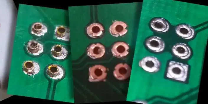
Inspection Methods

Inspection of rivet joints helps verify quality and strength. Some key inspection aspects:
Flaring Shape
- Flare should reach close to hole edges without exceeding
- Flare should have smooth, symmetric shape
Head Seating
- Head should sit flat against flange surface
- No gaps between flange and head
Hole Filling
- Flare should fill at least 80% of hole area
- Little unfilled space visible around rivet body
Board Condition
- Check for lifted copper pads, cracks, or delamination
- Indicates excess force or stress
Both visual inspection and tools like x-ray imaging can provide insight into internal rivet structure. Testing sample rivets to failure determines shear and tensile strength.
Advantages vs. Screws
Let’s also discuss some benefits of using PCB rivets compared to screws:
Vibration Resistance
Rivets form a fixed, non-moving joint. This resists loosening over time from vibration. Screws are susceptible to backing out.
Assembly Speed Rivet installation is faster than driving screws. Large volumes of rivets can be quickly installed.
Reduced Components
Rivets don’t require extra components like washers, screw threads, and nuts. The rivet body provides an all-in-one fastener.
Material Options
Rivets come in more materials than screws such as titanium. This provides flexibility for specialized applications.
Lower Profile
Rivet heads can be less protrusive than screws. Flatter profiles are possible.
Improved Appearance
For external applications, rivets offer a more finished look compared to exposed screw heads.
The permanence and tight fit of rivets makes them ideal for PCB connections under vibration and longevity requirements.
Frequently Asked Questions
Some common questions that arise around PCB rivets:
How are hole size and rivet size matched?
Generally select a rivet shank 0.1-0.3 mm smaller than the hole. The flare fills the remaining space to create a tight assembly.
What tools are needed for installation?
Blind rivets require only simple handheld or pneumatic pull tools. Solid rivets need more advanced rotary-pull tools for best connections.
What force is needed to shear rivet joints?
Well installed rivets offer over 1,000 KgF shear strength and close to 2,000 KgF of tensile strength depending on the rivet size and material.
Can repetitive assembly/disassembly damage rivet holes?
Yes, hole plating and structure can degrade with repeated rivet removal and re-work. Permanent press-fit pins may be better for field replacement needs.
How many boards can be riveted before re-tooling is needed?
On the order of 500 rivet cycles can be achieved before typical hand tools require adjustment, cleaning, or replacement of worn parts.
In summary, matching rivet type and geometry for the design needs is key for achieving robust, reliable PCB connections.
Conclusion
Riveting provides a strong, vibration-resistant means of mechanically attaching PCBs. The versatility of rivet styles and materials allows an ideal solution to be tailored for the design requirements. With careful hole layout and quality installation practices, riveted connections outperform traditional screw fastening.
While requiring some upfront planning, the long term benefits are significant. The permanence of rivets prevents loosening while their simplicity speeds assembly. Riveting improves product life, assures proper grounding, and enhances aesthetics.
So for your next design needing robust board mounting, look beyond just screws. The wide capabilities of PCB riveting make it a compelling alternative for connectors, EMI shielding, board stacking, and other attachments. With the guidelines presented here, you’ll be ready to implement riveted connections that maximize reliability.