Printed circuit boards (PCBs) form the backbone of electronics products housing several crucial components. PCBs utilize tiny metallic tracks deposited on insulating substrate to interconnect components forming functional circuits. Signals enter and leave the PCB through connectors interfacing with other world interfaces.
Edge mount connectors facilitate connecting external devices or cables to board’s edges without occupying valuable board real estate. They deliver signals through durable, replaceable interfaces mounted along periphery of boards.
This article explores PCB edge mount connectors examining types, benefits, mounting considerations and installation processes.
What is PCB Edge Mounting?

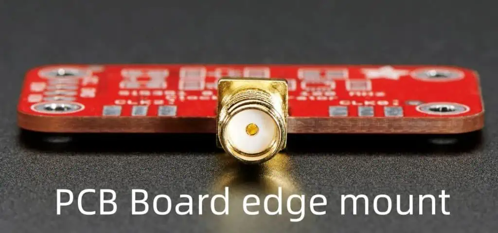
PCB edge mounting refers to interfacing external electronics to a printed circuit board by installing connector modules along the edges of the board instead of directly soldering cables.
They are commonly used in applications like:
- Pluggable daughtercards in large systems
- Digital processor and memory card add-ons
- Control equipment sensor wiring interfaces
- Analog data acquisition card cabling
Edge mount approach minimizes need for onboard connectors occupying valuable layout space. They simplify integrating additional functions through plug-in peripheral boards.
Why Use Edge Mount Connectors on PCBs
Installing durable edge connectors offer several advantages versus soldering wire harnesses directly:
Removability – Facilitates card swapping by avoiding direct cables soldering during upgrades
Pitch Options – High-density mounts maximize contacts in constrained PCB zones
Strain Relief – Robust housing withstands vibration, flexing, frequent mating cycles
Simplifies Testing – Test probe access to signals without affecting functioning system
Custom Configurations – Tailor edge card dimensions, contact density, placement etc. per application
Time Savings – Fast installation compared to manual wiring and strain relief
Edge mounts essentially modularize a PCB’s external interfaces allowing additional functions prototyped via plug-in approach. Let us look at various edge connector types available.
Types of PCB Edge Mount Connectors
Industry offers a range of durable PCB edge connectors targeted to different applications:
Board-to-Wire Edge Mounts
- Interconnects PCB to external device cables
- Insulation piercing contacts bite through insulation
- High density soil-resistant contact tails
- Operation up to 30 A/600 V rating
- Pitch options from 1.27 mm to over 5 mm
Uses: Industrial controllers, motor drives, power supplies
Board-to-Board Edge Connectors
Plug-in daughtercards or peripheral modules internally
- Gold plated contacts handle signals & power
- Up to 10 A per circuit, 300 V rating
- 1 mm to 2.54 mm pitch spacing
- Standoffs guide card alignment
Uses: Memory modules, telecom cards, test points
Wire-to-Board Single Row Headers
- Double beam female contacts
- Scoop-proof housings with board locks
- Stranded wire gauges up to 16 AWG
- Friction lock strain relief
- 1.27mm, 2.0mm, 2.54mm pitch options
Uses: Analog signals, electronic controls, measurement systems
This wide variety caters from low power signals to high current connections in diverse applications. Engineers enjoy flexibility to select optimal edge mount style for needs.
Key Considerations for Edge Connectors
Keep these aspects in mind when planning edge mounts on your PCB:
Pitch and Contact Density – Choose based on signal count and max board edge allotted
Current Loads – Seek connector slots to handle all power traces capacity
Mechanical Stresses – Account for vibration, temperature shifts, mating cycles
Signal Types – Want gold-plated contacts for low level logic, resistance modes?
User Access Needs – Consider wire-to-board headers for easy test probing
Assembly Methods – Pick types suiting soldering or press-fit technologies used
Compliance Needs – Meet safety, EMI/EMC specs like IPC, UL, CSA
Cost Targets – Compare compatible options fitting budget
Analyzing key technical and compliance requirements helps select optimal edge connectors fitting performance, reliability and budgets needs for target application.
PCB Edge Mounting Process Steps
Installing edge connectors require careful planning starting from product design stage. Let’s walk through the end-to-end PCB edge mounting steps:
1. Finalize Edge Zone
Determine maximum PCB real estate available for edge connector during board layout design. Account for panel spacing, device clearances and stiffness needs. Confine to one edge or distribute across sides.
2. Select Edge Mount Product
Choose connector model based on pitch, mating type, density, current capacity and compliance reports studied. Get free samples to gauge quality.
3. Design Housing Cutout
Specify connector footprint dimensions as board cutout in PCB CAD software. Carefully match with edge mount mechanical drawings. Account for tolerances.
4. Assign Reference Designators
Identify contact pad designators for assembly drawing and documentation. Add connector part in Bill of Materials (BOM) for procurement.
Get initial test boards made with panel cutouts. Confirm sample mounts correctly mate into slots before full production.
6. Perform Electrical Testing
Test continuity between board pads and edge mount tails to validate solder connections.
7. Carry Reliability Testing
Subject mated assembly to vibration, thermal cycling, mechanical shocks etc. Determine resultant signal integrity or intermittency before release.
8. Finalize Documentation
Update all component datasheets, reference design docs, assembly files and user manuals with edge mount details for production release.
While seemingly straightforward, meticulously executing each step verifies quality before product ships.
Now that fundamental knowledge is covered, let’s look at some real-world applications.
Example Application Cases
PCB edge mounting approach finds numerous applications for modular, accessible and condensed electronics:
Memory Module Edge Connectors
Dual Inline Memory Modules use high density board-to-board edge mounts to plug into motherboard sockets in personal computers. They allow upgrading system memory capacity via clip-in peripherals connected through gold plated contacts. Dense 1 mm pitch transports data, address and control signals reliably.
PLC Analog Signal Cards
Programmable Logic Controllers use edge mount daughtercards to enhance analog IO capabilities through convenient plug-in approach. Ribbon cables with insulation displacement terminals simplify field wiring handling voltage signals. Cards can be readily swapped without using tools meeting changing needs.
Inverter Drive Controller Cards
VFD motor drives use edge connectors to interface control electronics with high voltage inverter bridge modules. High density board-to-board mounts transport PWM logic signals with power plane. Connectors allow controller cards replaced in the events of drive firmware upgrades or transportability to other motor ratings. High temperature materials ensure durable performance in plethora of industrial ambients.
Creative PCB edge mounting opens up exciting possibilities for innovative electronics modularization in next generation products through stacking daughtercards, external instrument integration and functional upgrades.
Frequently Asked Questions
Q1. Can I solder wires directly to a PCB instead of edge connectors to save cost?
Soldering cable wires directly works for prototypes but not advisable for production due to field reliability concerns. Vibration and thermal movements crack joints over time requiring extensive rework. Edge mounts offer vibration-proof durability withstanding years mechanical stresses.
Q2. How many mating cycles do PCB edge connectors support?
Most board-to-board and board-to-wire models support 500-1000 mating cycles minimum. Heavy duty connectors using thicker gold plating on contacts manage >5000 insertion cycles. Careful material selection ensures years of replacements-free usage even in demanding industries like telecom, defense, aerospace etc.
Q3. Can edge mount connectors handle high speed data communication needs?
Yes, several edge mount models meet requirements of high speed protocols like PCI Express, USB 2.0, Ethernet, SATA etc. Careful contact density, gold plating thickness and molding geometry design ensures matched impedance signal transport minimizing distortions meeting industry standard compliance needs.
Q4. What are some best practices to install PCB edge connectors?
Some design and assembly recommendations include:
- Limit maximum board flexing through adequate stiffeners
- Utilize connector polarization features to avoid misinsertions
- Specify generous fillet radii matching mating chamfers
- Follow recommended torque levels for securing hardware
- Validate solder joint integrity after placements
- Lab test mated assemblies under environmental stresses
Q5. Can edge connectors be mounted on both sides of a PCB card?
Yes, many daughtercard applications utilize edge connectors on both sides. For example, dual inline memory modules use mirrored high density connectors on either sides to double signal contacts while meeting tight space constraints. Standoff heights are accordingly adjusted to ensure planarity across side-A and side-B connectors. Such configurations maximize edge card utilization.