
RAYPCB · ENGINEERING GUIDE
LED Light Assembly: Board, Optics, Housing and Final Test
LED light assembly brings a populated light engine together with its driver, wiring, optics, thermal interfaces and housing. The completed product can behave differently from the board tested on its own. A dependable assembly plan therefore follows the interfaces between parts and defines what the final test is intended to demonstrate.
This page addresses luminaire integration rather than duplicating the LED PCB manufacturing hub. It helps buyers describe the finished deliverable and gives engineers a sequence for identifying fit, thermal and test requirements. The planning tool estimates throughput from entered process assumptions; it does not state a factory capacity or delivery commitment.
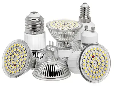
Define what arrives and what leaves the assembly process
List the supplied and purchased items: light engine, driver, housing, lens or diffuser, interface material, wiring, fasteners and labels. Identify who owns each drawing and approved supplier decision. A request for LED assembly can mean only PCB population or a complete boxed product; the quotation must make that boundary explicit.
Use an assembly drawing or exploded view that identifies orientation, mounting surfaces and cable routes. Dimensions should account for the actual tolerance stack rather than nominally matching parts. Connector access and service clearances are often easiest to review before the first build. If a fixture is required to hold alignment, include it in the manufacturing plan.
Define variants with a controlled BOM and configuration table. Different color temperatures, optics, currents or connector options may look similar while requiring different tests and labels. Do not rely on a handwritten instruction to distinguish production variants. The released identity should remain traceable through assembly, test and packaging.
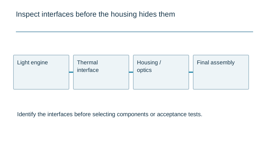
Control the thermal interface during assembly
The interface between board and housing can dominate the final thermal result. Specify the material, coverage, thickness or application method as appropriate to the approved design. Keep the contact surfaces and mounting procedure consistent. An uncontrolled adhesive layer or uneven seating can change heat transfer even when the light engine is electrically correct.
Fastener selection and tightening requirements belong in the mechanical design, including any sequence or torque specification established for the product. Do not invent a universal torque for LED boards. Excess force can distort a board or optical part, while insufficient contact can affect mounting and thermal behavior. The assembly method should reproduce the evaluated condition.
Check how wiring and components interact with the mounting surface. A trapped wire, protruding solder feature or misplaced insulator can change fit and electrical separation. Inspection should examine the relevant interface before it becomes inaccessible. Preserve evidence of the process step where final visual inspection cannot observe the hidden condition.
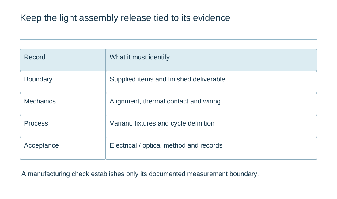
| Review item | What to establish |
|---|---|
| Boundary | Bare light engine versus programmed or complete luminaire delivery. |
| Mechanics | Tolerance, thermal interface, fasteners and accessible inspection steps. |
| Optics/wiring | Orientation, cleanliness, strain relief and installed cable arrangement. |
| Process | Variant identity, sequence, cycle basis and bottleneck assumptions. |
| Acceptance | Electrical, optical, thermal and packaging requirements with records. |
Preserve optics and electrical interfaces
Optical components need correct orientation, spacing and cleanliness. Scratches, contamination or mechanical strain can alter the distribution without creating an electrical failure. Define handling and cleaning methods using the actual material requirements. A generic solvent recommendation can damage a lens or optical coating.
For wiring, identify polarity, connector keying, strain relief and routing relative to heat sources and moving or sharp features. The electrical test should use the final cable configuration where it affects behavior. A board that passes on a short bench lead may respond differently after installation with the intended harness.
The LED strip guide is useful when the light source is distributed along a channel or housing. Feed locations and segment current remain part of the electrical design. A mechanical installer should not have to invent extra feeds to compensate for an undocumented voltage-drop problem.
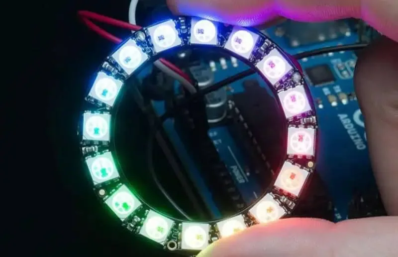
Plan the sequence around observable interfaces
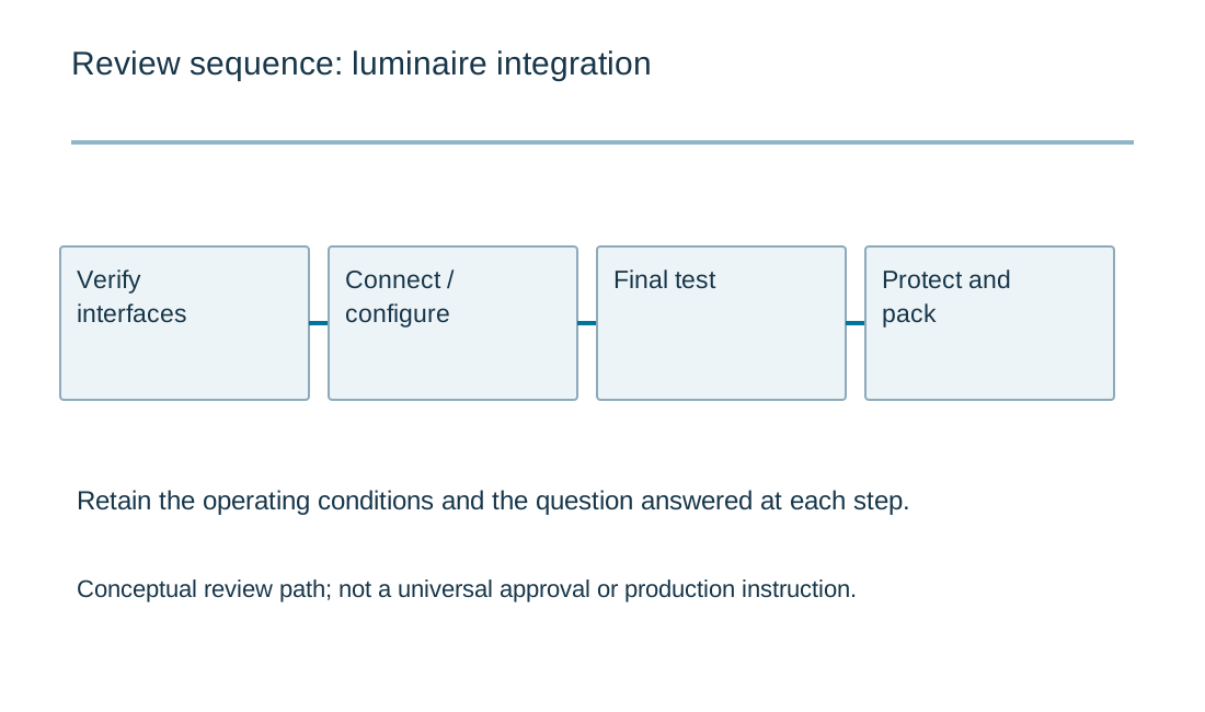
Arrange operations so critical features are checked before they are covered. For example, inspect the thermal interface and wire route before closing a housing that prevents later access. Identify steps that can contaminate optical surfaces and position their cleaning or protection accordingly. The sequence should serve the product rather than simply copy another assembly line.
Define programming or configuration at a stage where access is reliable. Verify the intended current or mode before installing an inaccessible cover. If a final test fails, the diagnosis and rework route should preserve the product's controlled construction. Repeated disassembly may require replacement of an interface material or seal rather than simple reclosure.
Keep a traveler or equivalent record for the operations that matter to acceptance. It should identify product revision, variant, relevant component lots and test outcome without collecting unnecessary information. A record is useful when it explains how the delivered unit was made, not merely because it contains many checkboxes.
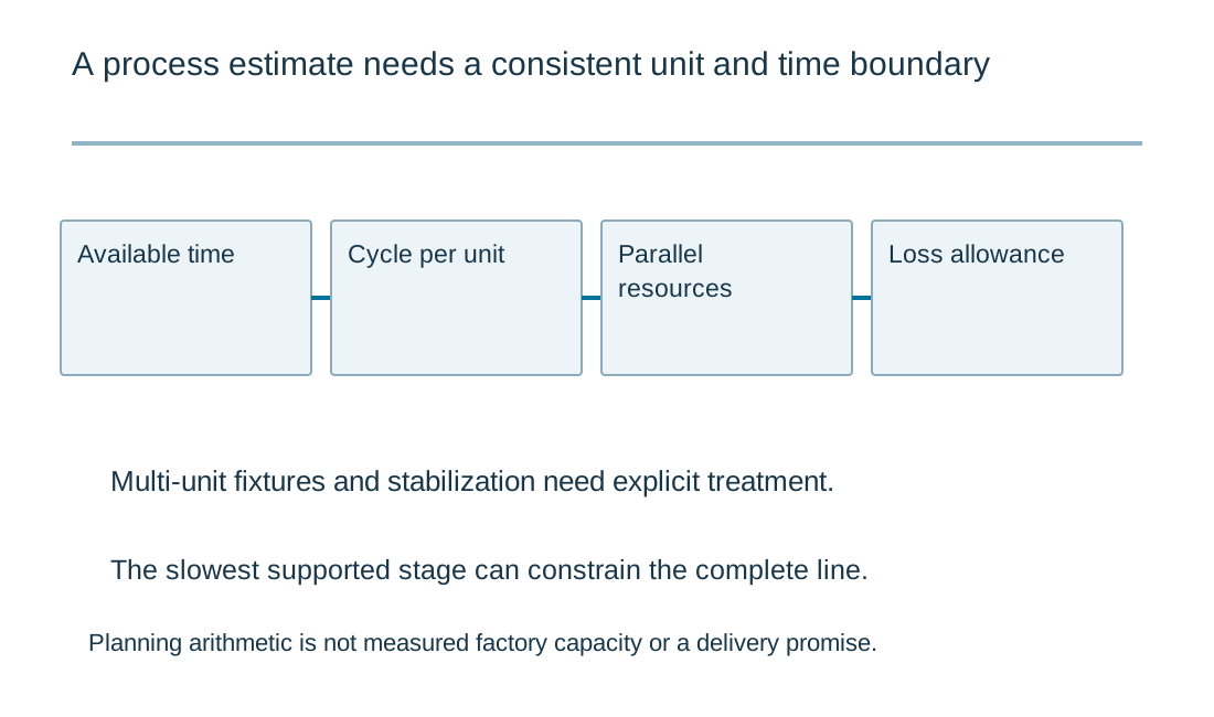
Interpret throughput as a process model
The worksheet uses the entered cycle time, available time, parallel resources and loss assumptions to estimate output for the stated scenario. Define whether a cycle refers to one unit or a multi-unit fixture. Include loading, unloading and any required stabilization in the appropriate part of the process model rather than hiding them outside the timing boundary.
If a test holds several units for a long duration, its capacity may differ from the manual assembly station. Parallel fixtures and batch operations require a consistent unit basis. A simple throughput calculation does not prove that every station, material supply and operator can sustain the result. Review the bottleneck and the actual work sequence.
Use observed or clearly labeled planning values. Do not present an assumed efficiency as measured factory performance. The optional cost worksheet similarly adds user-entered allowances; it is not a live labor rate or a delivery promise. The value of both tools is a transparent comparison of scenarios before a detailed manufacturing proposal.
Production test station capacity
Production test station capacity
Use the current inputs and keep the assumptions
Load the example to inspect its units, then clear it before entering your own revision. Example values are deliberately labeled assumptions. Complete every field; an empty numeric input is not zero. Record the operating condition behind a value rather than copying the first number found on a component summary. For a comparison, keep the measurement boundary and units consistent.
Calculate after checking the inputs. Any edit invalidates the old result and disables its report download until you calculate again. An edited example remains identified as an example. Results and reports are generated locally without uploading a circuit or populating Contact. Attach the downloaded text manually if it helps explain the question. You can request a review directly without completing the tool.
| Input | What to establish before using it |
|---|---|
| Review reference | Nonconfidential revision label. |
| Station occupancy per unit · s | Include load, programming, measurements and unload when they occupy the station. |
| Independent parallel stations | Integer; stations must actually be able to operate concurrently. |
| Scheduled time · h | Length of the planning interval. |
| Usable scheduled fraction · % | Entered allowance for downtime; not an observed factory performance claim. |
| Units planned | Integer; first-pass cycles only. Retest and yield require separate evidence. |
Optional cost comparison from your own allowances
Use a quotation or a clearly labeled internal assumption for each input. Keep the quantity, construction and inspection scope the same when comparing alternatives. This uncalibrated planning model adds entered values; it contains no current market rates and does not issue a RAYPCB quotation. You can contact the team without completing it.
Optional project allowance comparison
Define final acceptance and packaging
Final electrical checks should state the supply, mode and observed quantities. Optical checks need a declared geometry and operating condition. Thermal characterization may require a different duration and setup from routine production testing. The LED quality-control page explains these evidence boundaries and how retest results should be counted.
For specialized products such as grow-light assemblies, use the correct photon quantities and spectral scope in the acceptance specification. Do not substitute a general brightness reading for a requirement it cannot measure. Preserve the fixture configuration and test-program revision so repeat production can be compared meaningfully.
Packaging should protect optics, connectors and mechanical interfaces in the intended transport arrangement. Identify required labels, accessories and assembly instructions. For a RAYPCB inquiry, provide the controlled product files, quantity, supplied-part list and the operations requested. This allows the proposal to cover the actual light assembly and the evidence delivered with it, rather than only the visible PCB.
Make final test a repeatable manufacturing task
Specify what enters the station, what is assembled or programmed, and what leaves as an accepted unit. A time estimate has little meaning if it omits fixture loading, stabilization, optical positioning or record storage. Shared instruments and operators can limit throughput even when multiple fixtures exist.
Separate first-pass results from retest and repair history. Keep firmware, test software, fixtures and acceptance criteria aligned with the hardware revision. If an enclosure or optical part changes, review the complete acceptance boundary. The supplier can then quote setup, recurring assembly and test work as explicit tasks. No downloaded report represents a factory capacity commitment or an independently verified production result.
Standards, source context and limits
Use the exact device revision and application conditions when applying manufacturer guidance. Reference designs are evidence about a specified implementation, not automatic validation of a modified board. Workmanship inspection, functional verification, product safety and application performance are different acceptance tasks. Public summaries do not replace the applicable licensed standards or a project-specific acceptance specification.
For fabrication scope and the agreed construction requirements, see PCB manufacturing.