Prototype boards, also known as breadboards or solderless boards, are reusable circuit building tools used to prototype and test electronic designs during development. They allow creators to quickly connect and alter component configurations without any soldering.
This comprehensive guide will explain what prototype boards are, why they are useful, the different types available, and provide step-by-step instructions on how to effectively utilize them for electronics prototyping, including:
- Understanding the internal connections
- Mounting various components
- Building basic to complex circuits
- Troubleshooting issues
Follow along to learn hands-on skills for rapidly assembling electronics on prototype boards!
What Are Prototype Boards?

A prototype board or breadboard provides a convenient grid of interconnected spring clips and contact holes into which you can insert electronic components to construct a circuit, without any soldering involved.
Benefits
Here are the key advantages of using a prototype board:
- Reusable – Allows repeated connecting and disconnecting of parts
- Solderless – No soldering required for setting up circuits
- Adjustable – Easy to alter component placements
- Testable – Facilitates testing of circuit operation
- Inexpensive – Affordable even for hobbyists
By letting you easily swap arrangements of integrated circuits, resistors, capacitors, inductors and more to form a circuit, prototype boards enable iterative electronic testing and troubleshooting.
Types of Prototype Boards
There are a few varieties of solderless breadboards or prototype boards:
1. Classic Breadboard
This is the most common type, providing connected horizontal rows of clip holes into which component leads or jumper wires can be inserted. The rows are divided in the center, with a positive and negative distribution bus line running vertically to supply power.
2. Mini Breadboard A smaller version of the classic breadboard with limited rows, portable for tiny projects.
3. Perfboard Instead of clips, perfboard offers an array of machined holes into which component leads can be hand-soldered. Allows more permanent assemblies.
4. Modular Breadboards For complex projects, modular breadboards can snap together to expand the prototyping area.
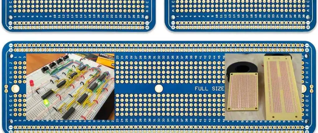
Inside a Breadboard
Looking inside a classic full-sized breadboard reveals how the spring-loaded clips provide electrical connectivity:
The black clips and holes are encased in clear plastic shells to provide insulation from neighboring rows. Metal nickel alloy leaves inside each clip provide electrical spring contact when component leads are inserted.
Rows marked with a – or + indicate connection leads out to the negative and positive bus lines on each side. This lets you easily distribute power supply voltages across the board.
Understanding these internal electrical connections is essential for planning your breadboard layouts!
Mounting Components on Breadboards
Components can be easily secured into a prototype board by plugging their lead wires or pins into the spring clip holes:
Insert Wires & Leads
1. Identify polarity indicators like +/- signs, long/short wire leads or pin positions. Align the positive and negative sides correctly.
2. Push leads/pins in firmly so they make contact with the metal leaves inside. But don’t over tighten or you may damage the contacts.
3. Ensure aligned rows to complete a connected circuit across adjacent clips. Misaligned rows will break connectivity.
4. Use jumper wires to bridge non-adjacent rows and route connections around as needed.
Mount ICs & Sockets
1. Outline the IC footprint by anchoring both ends in the same row.
2. Align Pin 1 markers correctly relative to internal rows.
3. Splay lateral pins outwards across adjacent contact clips for stability.
4. For sockets, mount them first, before plugging ICs into socket. Pressure fit for retention.
Here is a diagram showing insertion of common parts:
Correct positioning ensures reliable connectivity throughout your prototyped circuits!
Breadboard Circuit Basics
Understanding basic prototype board connectivity allows you to transform schematics into physical layouts:
Tips
- Start simple before increasing complexity
- Verify alignments to schematics
- Distribute power rails across rows
- Bridge connections cleanly
- Recheck contacts intermittently
Follow these prototyping best practices as you advance your circuits towards completion!
Complex Breadboard Projects
For intricate projects with higher component counts, utilize larger breadboards or modular linking for expanded capacity:
Considerations
- Section functions into sub-units
- Designate isolated power zones
- Label rows and connections
- Allow room for tweaking parts
- Verify builds incrementally
Careful planning is key for keeping complex prototypes understandable and debuggable!
Breadboard Circuit Troubleshooting
Despite best efforts, prototypes may occasionally run into issues. Here is how to troubleshoot:
No Power
- Check battery clips or power plugs
- Test supply voltage presence on rails
- Measure continuity out to rows
Short Circuits
- Validate only intended connections
- Eliminate solder fragments shorting clips
- Prevent lead wires contacting closely
Erratic Operation
- Redo all component insertions
- Rule out cold joints or faulty parts
- Reflow suspect solder points
- Examine clips/ Sockets for wear debris
Methodically isolating the source from power input to individual sections will help identify any breadboard problems for correction.
Prototype Board Tips

Follow these handy guidelines for smoother prototyping sessions:
Part Insertion
- Push wires and leads fully in without over bending them
- Angle wider leads into offset holes for a snug fit
- Use pliers to trim excess lead lengths
Stable Layouts
- Heavier sections first, then build outward
- Place adhesive foam under boards
- Avoid lifting boards by protruding wires
Repeated Revisions
- Preserve plugged layouts with photos
- Label wire free ends by function
- Clean clip debris before major changes
Once comfortable, prototype boards will accelerate your DIY electronics builds and learning!
Frequently Asked Questions
Q: How do I get a reliable connection to clips?
A: Check for shiny metal contact at lead insertion points. If inserts are loose, squeeze the surrounding plastic gently to increase grip, or change holes. Avoid wiggling inserted leads.
Q: My board has a manufacturing defect. Should I tear off the damaged section?
A: No, remove damaged portion with precision tools to avoid cracking cases open. Even small inner separations can impact electrical connectivity. Test for shorts after any invasive modification.
Q: Can prototype boards handle high voltages or power levels?
A: Most consumer boards are rated for under 25V and 500-1000mA max current only. For driving higher loads, research specialty breadboards or simply solder up finalized prototypes on perfboards/PCBs.
Q: Is it possible to burnout internal clips or connections through misuse?
A: Yes, repeated short circuits or extreme overheating can melt internal alloy contacts, cracking cases when expanding gas builds up. Avoid exceeding rating and rectify shorts quickly.
Q: Do breadboards ever need cleaning or maintenance?
A: Over time clip grip may loosen after frequent lead inserts/removals or environmental grime can accumulate. Use isopropyl alcohol with cotton buds to clean contact posts when necessary.
Conclusion
Prototype boards offer wonderful platforms for conveniently constructing, testing and modifying temporary electronic circuits with no soldering necessitated. Their spring contact holes allow you to securely host components in customized arrangements simply by plugging leads in to form desired connections.
Leverage breadboards to boost your hands-on learning when prototyping fresh designs from concept through maturation. The ability to rapidly alter layouts by just popping parts in and out of reusable boards accelerates iterative development, debugging, and functionality enhancement.
With practice, prototype boards become indispensable tools for giving creative outlet to electronic ideas as you advance from simple hookups towards ever more intricate projects! Just follow fundamental mounting guidelines, plan effective layouts for clean routing, and regularly validate contact integrity at insertion points.
So jump straight into prototyping your next electronic innovations on versatile breadboards before migrating successful verified builds onto permanent soldered PCBs or stripboards towards final deployment!