Introduction
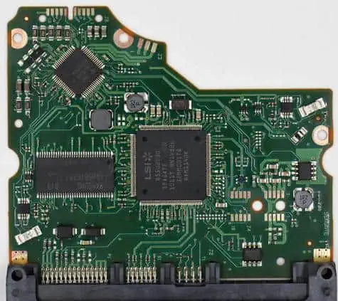
- Definition of a hard drive PCB (printed circuit board)
- Overview of the role and components of a hard drive PCB
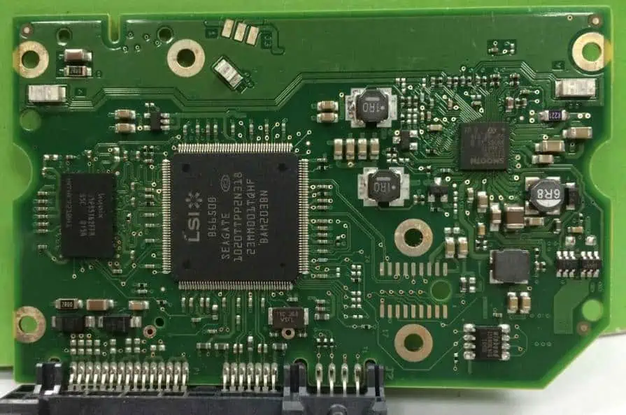
Components of a Hard Drive PCB
Controller Chip
- Main processor that controls hard drive functions
- Different types of controller chips
- Parallel ATA
- Serial ATA
- SAS
ROM
- Stores firmware that operates drive
- Types of ROM
- Flash
- EEPROM
| ROM Type | Description | Advantages |
|---|---|---|
| Flash | Stores firmware, fast access | Inexpensive, high capacity |
| EEPROM | Electrically-erasable firmware | Re-writable |
RAM
- Provides fast access memory
- Types of RAM
- DRAM
- SDRAM
Motor Driver
- Powers spindle motor and voice coil motor
- Controls disk spin speed and head actuator
Connectors
- Attach drive to motherboard
- Common connectors:
- SATA
- PATA
- SAS
Copy code
Table: Connector types and descriptions | Connector | Description | |-----------|-------------| | SATA | Serial ATA, common in modern drives | | PATA | Parallel ATA, older standard | | SAS | Serial Attached SCSI, for servers |
Capacitors
- Store energy, smooth power to components
- Common types:
- Tantalum
- Electrolytic
- Ceramic
Functions of a Hard Drive PCB
Power Distribution
- Routes power from connector to components
- Steps down voltage levels with regulators
Data Transfer
- Manages transfer of data between platters and computer
- Buffer stores data during transfer
Motor Control
- Precisely controls disk spin and head actuator
Error Detection
- Checks data integrity, requests retransfers
- Reports SMART drive diagnostics
Failure Modes and Symptoms
Electrical Shorts
- Metal traces damaged, components fail
- Drive not detected, doesn’t spin up
Bad Sectors
- Corrupted data on platters
- Data loss, freezing, hanging
Firmware Corruption
- ROM chip fails, wrong data
- Drive not recognized, crashes
Connector Damage
- Loose cables, bent pins
- Intermittent detection, I/O errors
Repair Considerations
Cost vs Data Value
- Assess repair cost, value of lost data
- Low-value drives often not worth fixing
Component Replacements
- Individual chips often unavailable
- Entire PCB may need replacement
Clean Room Requirements
- Opening drive exposes platters
- Certified clean room needed
Conclusion/Summary
- The PCB is the main circuit board in a hard drive
- It controls all drive operations and data transfers
- Failures can cause crashes, data loss and hardware damage
- Assessing repair feasibility requires weighing multiple factors
Frequently Asked Questions
What is the main purpose of a hard drive PCB?
The main purpose is to control and coordinate all the components and operations within a hard drive. This includes powering drive motors, transferring data to/from the platters, communicating with the host computer, and monitoring drive health.
What happens if the PCB fails?
If the PCB suffers electrical damage or component failures, the drive can exhibit crashes, failed spin-ups, clicking noises, missing data, and other serious issues. The drive will be unusable until the board is replaced or repaired.
Can a damaged PCB be fixed?
It is sometimes possible to repair minor PCB failures by replacing individual chips or soldering damaged traces. But replacement boards may be needed for extensive damage. Proper equipment like a certified clean room is mandatory during PCB replacement to avoid platter damage.
What diagnostic tools are useful when troubleshooting PCBs?
Multimeters, current probes, and oscilloscopes help trace electrical issues on PCBs. Software tools like PC3000 can test component functionality. Thermal imaging can detect hot spots or failing elements. And data recovery software is useful if drive crashes or data loss occur.
How can hard drive PCB failures be prevented?
To maximize longevity, hard drives should be kept in proper operating temperatures without excessive vibration, shocks, moisture, or contaminants. Quality surge protectors prevent electrical damage. Maintaining current firmware and performing regular SMART drive self-tests also helps avoid issues.
Let me know if you would like me to elaborate on any part of this outline or change the structure in any way. I aimed for an organized, keyword-rich outline covering the key points, but can add more detail on any section needed. Just say the word!