Executive Summary
The Effective Number of Bits (ENOB) represents one of the most critical yet often misunderstood specifications in modern oscilloscope design. Unlike simple bit resolution specifications, ENOB quantifies the actual analog-to-digital conversion performance under real-world operating conditions, accounting for the complex interplay of noise, distortion, and system-level impairments that characterize high-performance measurement instruments. This comprehensive analysis examines the fundamental principles governing ENOB, its measurement challenges, and its practical implications for precision electronic measurements.
Introduction: Beyond Theoretical ADC Resolution
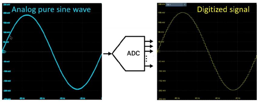
In the realm of high-frequency electronic measurements, oscilloscopes serve as the primary interface between analog phenomena and digital analysis. The quality of this analog-to-digital conversion fundamentally determines measurement accuracy, dynamic range, and signal fidelity. While traditional ADC specifications focus on theoretical bit resolution (K), where quantization occurs across 2^K discrete levels, real-world performance requires a more nuanced understanding of effective resolution.
ENOB emerges as the definitive metric for characterizing actual ADC performance, representing the number of bits that contribute meaningful information to the measurement process. For instance, while a 12-bit ADC theoretically provides 4,096 quantization levels, real-world implementations typically achieve ENOB values between 10.5 and 11.5 bits, corresponding to effective resolutions of approximately 1,500 to 3,000 meaningful levels.
Theoretical Foundation: The Relationship Between SNR and ENOB
The mathematical relationship between ENOB and Signal-to-Noise-and-Distortion Ratio (SINAD) forms the cornerstone of ADC performance analysis. According to IEEE Standard 1241-2010, ENOB can be expressed as:
ENOB = (SINAD – 1.76) / 6.02
Where SINAD represents the power ratio of signal to noise plus distortion, expressed in decibels. This relationship assumes sinusoidal input signals and establishes the fundamental limit that each additional effective bit corresponds to approximately 6.02 dB of SINAD improvement.
The theoretical maximum SINAD for an ideal K-bit ADC equals 6.02K + 1.76 dB, where the 1.76 dB term accounts for quantization noise characteristics in sinusoidal signals. However, practical implementations fall significantly short of this theoretical limit due to various system impairments.
System-Level Factors Affecting ENOB Performance
1. ADC Module Limitations
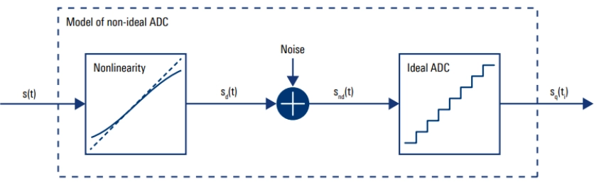
Modern high-speed ADCs exhibit several non-ideal characteristics that directly impact ENOB performance:
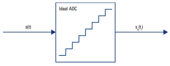
Quantization Noise: Even ideal ADCs introduce quantization noise with an RMS value of LSB/√12, where LSB represents the least significant bit voltage. This fundamental noise floor establishes the theoretical ENOB limit.
Differential Nonlinearity (DNL): Variations in quantization step sizes introduce distortion components that reduce effective resolution. DNL specifications typically range from ±0.5 to ±1.0 LSB in high-performance ADCs.
Integral Nonlinearity (INL): Systematic deviations from the ideal transfer function create harmonic distortion, particularly problematic for high-frequency signals where linearity requirements become increasingly stringent.
Aperture Jitter: Timing variations in the sampling process introduce noise that scales proportionally with input signal frequency and amplitude, making ENOB inherently frequency-dependent.
2. Front-End Signal Conditioning Impairments
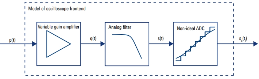
The oscilloscope’s analog front-end significantly influences overall ENOB performance through several mechanisms:
Variable Gain Amplifier (VGA) Characteristics: VGAs provide the dynamic range adjustment necessary for optimal ADC utilization but introduce frequency-dependent nonlinearities, particularly at higher gain settings. Typical VGA implementations exhibit third-order intercept points (IP3) ranging from +20 to +35 dBm, limiting large-signal linearity.
Anti-Aliasing Filter Performance: Analog low-pass filters prevent aliasing but introduce group delay variations, amplitude ripple, and phase nonlinearity that degrade signal fidelity. The trade-off between filter sharpness and phase response directly impacts ENOB, particularly for broadband signals.
Input Protection and ESD Circuits: Necessary protection elements introduce parasitic capacitances and nonlinear junction effects that become increasingly problematic at higher frequencies.
3. Thermal and Environmental Effects
Temperature variations affect component characteristics throughout the signal path:
ADC Temperature Drift: Reference voltage variations, comparator offset drift, and timing variations all contribute to temperature-dependent ENOB degradation.
Front-End Component Drift: VGA gain variations, filter characteristic changes, and impedance matching variations introduce measurement uncertainties that manifest as effective ENOB reduction.
Frequency-Dependent ENOB Characteristics
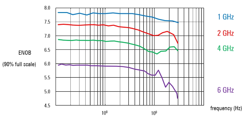
ENOB performance exhibits strong frequency dependence due to several physical phenomena:
Bandwidth Limitations: As signal frequencies approach the oscilloscope’s analog bandwidth, various parasitic effects become dominant, including:
- Skin effect losses in conductors
- Dielectric losses in substrates and interconnects
- Parasitic reactances that affect impedance matching
Sampling Clock Jitter: The relationship between jitter-induced SNR degradation and frequency follows: SNR_jitter = -20·log₁₀(2π·f·σ_jitter)
Where f represents signal frequency and σ_jitter represents RMS jitter. This relationship explains why ENOB typically decreases by 6 dB per octave increase in frequency.
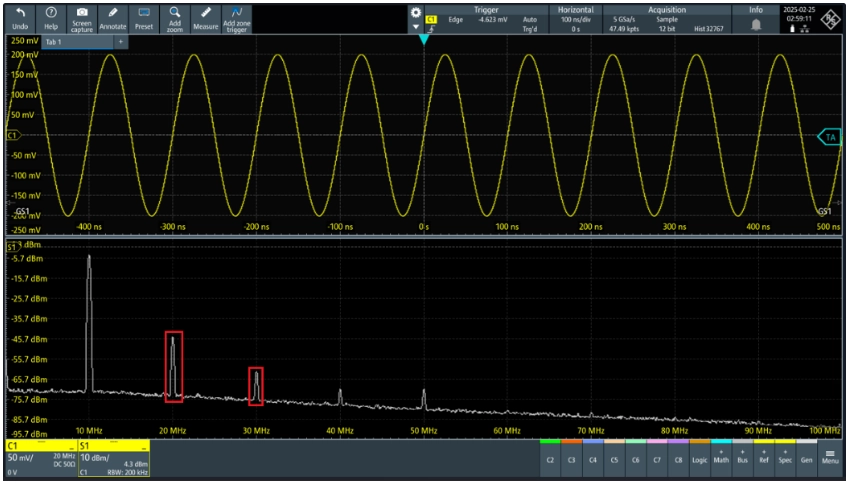
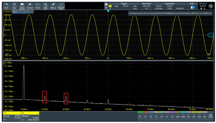
Harmonic Distortion Mechanisms: High-frequency signals exacerbate nonlinear effects in active components, generating harmonic and intermodulation products that directly reduce SINAD.
Measurement Methodology and Challenges
Signal Source Requirements
Accurate ENOB characterization demands signal sources with substantially better spectral purity than the device under test. Key requirements include:
Total Harmonic Distortion (THD): The source THD should be at least 10 dB better than the expected oscilloscope performance. For oscilloscopes with 60 dB SINAD, sources with THD < -70 dB become necessary.
Phase Noise Performance: Low phase noise ensures that jitter contributions from the source don’t dominate the measurement. Typical requirements specify phase noise < -130 dBc/Hz at 1 kHz offset for precision ENOB measurements.
Amplitude Stability: Long-term amplitude variations should remain within ±0.1 dB to ensure measurement repeatability.
Configuration Dependencies
ENOB measurements exhibit sensitivity to numerous oscilloscope settings:
Input Coupling Configuration: 50Ω vs. 1MΩ input impedance selection affects front-end noise figures and linearity characteristics. The 50Ω path typically provides better ENOB performance due to optimized impedance matching and reduced parasitic effects.
Vertical Sensitivity Optimization: ENOB generally improves when input signals approach full-scale deflection, maximizing SNR. However, overdrive conditions must be avoided to prevent compression-induced distortion.
Bandwidth Limitation Settings: Engaging bandwidth limit filters reduces high-frequency noise at the expense of signal rise time. The optimal setting depends on the specific measurement application and signal characteristics.
Averaging and Acquisition Parameters: Sample rate selection, record length, and averaging modes all influence measured ENOB values through their effects on noise floor and spectral resolution.
Practical Implications for Measurement Applications
Dynamic Range Considerations
ENOB directly determines the oscilloscope’s ability to resolve small signals in the presence of larger ones. For applications requiring wide dynamic range measurements:
Spurious-Free Dynamic Range (SFDR): ENOB establishes the theoretical limit for SFDR according to: SFDR ≈ 6.02·ENOB + 1.76 dB
Noise Floor Limitations: The effective noise floor equals full-scale range divided by 2^ENOB, establishing minimum detectable signal levels.
Signal Integrity Analysis
For high-speed digital applications, ENOB performance directly impacts:
Eye Diagram Measurements: Reduced ENOB manifests as increased noise in eye diagrams, potentially masking real jitter and noise contributions.
Jitter Analysis Accuracy: Phase noise measurements require high ENOB to distinguish between real jitter and measurement noise, particularly for low-jitter clock sources.
Power Supply Ripple Measurements: PSRR analysis demands high ENOB to characterize small ripple signals in the presence of DC bias levels.
Industry Perspectives and Best Practices
Specification Interpretation
When evaluating oscilloscope ENOB specifications, engineers should consider:
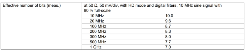
Test Conditions: ENOB values are meaningful only when accompanied by complete test condition specifications, including frequency, amplitude, and configuration settings.
Frequency Response Characterization: Single-point ENOB specifications provide limited insight; frequency-dependent ENOB curves offer more comprehensive performance assessment.
Application-Specific Requirements: Different measurement applications prioritize different aspects of ENOB performance, requiring careful specification analysis.
Optimization Strategies
To maximize ENOB performance in practical applications:
Signal Level Optimization: Utilize maximum available input range without causing compression or clipping.
Bandwidth Matching: Select minimum bandwidth adequate for signal characteristics to minimize noise contributions.
Environmental Control: Maintain stable operating temperatures and minimize electromagnetic interference sources.
Calibration Protocols: Implement regular calibration procedures to maintain optimal ENOB performance over time.
Future Trends and Technological Developments
Advanced ADC Architectures
Emerging ADC technologies promise improved ENOB performance:
Time-Interleaved Architectures: Multi-channel ADC implementations enable higher sample rates while maintaining resolution, though calibration complexity increases significantly.
Hybrid ADC Designs: Combinations of flash, SAR, and delta-sigma architectures optimize performance for specific frequency ranges and resolution requirements.
Digital Correction Techniques: Advanced digital signal processing enables real-time correction of ADC nonlinearities, potentially improving ENOB by 1-2 bits.
System Integration Advances
Monolithic Integration: System-on-chip implementations reduce parasitic effects and improve matching between signal path components.
Advanced Packaging Technologies: 3D integration and advanced substrate technologies minimize interconnect-induced degradation.
AI-Enhanced Calibration: Machine learning algorithms enable adaptive calibration and compensation for temperature, aging, and process variations.
Conclusion
ENOB represents a comprehensive metric that encapsulates the complex interplay of factors affecting oscilloscope measurement quality. Unlike simple bit resolution specifications, ENOB reflects real-world performance limitations arising from ADC impairments, front-end nonlinearities, environmental effects, and system-level interactions.
Understanding ENOB’s frequency dependence, measurement challenges, and practical implications enables engineers to make informed decisions regarding oscilloscope selection and optimization. As measurement requirements continue to evolve toward higher frequencies, greater dynamic range, and improved precision, ENOB will remain the definitive metric for characterizing analog-to-digital conversion quality in high-performance oscilloscopes.
The future of oscilloscope technology lies in addressing the fundamental limitations that constrain ENOB performance through advanced ADC architectures, improved system integration, and intelligent calibration techniques. By maintaining focus on these system-level performance metrics, the industry can continue advancing measurement capabilities to meet the demands of next-generation electronic systems.