The transition from lead-based to lead-free soldering has fundamentally changed the requirements for reflow thermal profiles in electronics manufacturing. Lead-free solder alloys, primarily SAC (Tin-Silver-Copper) compositions, require higher processing temperatures and more precise thermal control than their leaded counterparts. Understanding how to establish optimal thermal profiles is crucial for achieving reliable solder joints while preventing component damage and board warpage.

Understanding Lead-Free Solder Characteristics
Lead-free solders present unique challenges that directly impact thermal profile design. The most common lead-free alloy, SAC305 (96.5% Tin, 3.0% Silver, 0.5% Copper), has a melting point of approximately 217°C, significantly higher than the 183°C melting point of traditional 63/37 lead-tin solder. This temperature difference necessitates peak reflow temperatures typically ranging from 245°C to 260°C, compared to 215°C to 230°C for leaded processes.
The higher processing temperatures create several implications for profile development. Components must withstand greater thermal stress, requiring careful consideration of moisture sensitivity levels and thermal shock resistance. Additionally, the narrower process window of lead-free solders demands more precise temperature control throughout the reflow process. The wetting characteristics of lead-free alloys also differ, with slower wetting speeds and different surface tension properties affecting joint formation.
The Four Critical Phases of Lead-Free Reflow
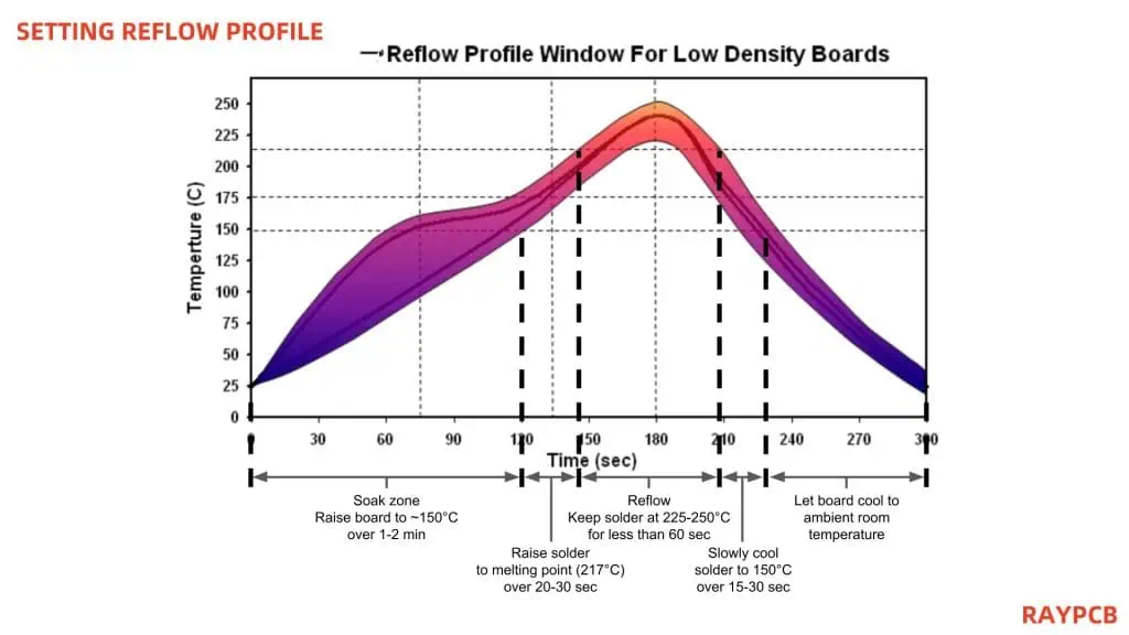
A properly designed lead-free thermal profile consists of four distinct phases, each serving specific metallurgical and process objectives. Understanding these phases is essential for creating profiles that produce reliable solder joints consistently.
Preheat Phase
The preheat phase establishes the foundation for successful reflow by gradually raising the assembly temperature from ambient to approximately 150°C. This phase typically lasts 60 to 120 seconds and serves multiple critical functions. The gradual temperature rise minimizes thermal shock to components, particularly important for larger or thermally sensitive parts. During preheating, solder paste flux begins activating, starting the process of oxide removal from pad and component surfaces.
The temperature ramp rate during preheat should be controlled between 1°C to 3°C per second. Excessive ramp rates can cause thermal shock, leading to component cracking or delamination, while insufficient ramp rates may result in incomplete flux activation and extended cycle times. The endpoint of the preheat phase is typically defined as the temperature at which the assembly reaches thermal equilibrium, ensuring uniform heating across all components.
Thermal Soak Phase
The thermal soak phase, occurring between 150°C and 217°C, is arguably the most critical phase for lead-free soldering success. This phase typically lasts 60 to 120 seconds and must be carefully controlled to achieve proper flux activation without premature solder reflow. During thermal soak, the flux continues its cleaning action, removing oxides and preparing surfaces for optimal wetting.
The temperature profile during thermal soak should maintain a controlled ramp rate of 0.5°C to 2°C per second. This moderate heating rate ensures complete flux activation while preventing thermal damage to components. The upper temperature limit of the soak phase is particularly important – exceeding 217°C will cause premature melting of the solder paste, potentially leading to component movement or tombstoning.
Temperature uniformity across the assembly becomes critical during thermal soak. Large temperature gradients can cause differential thermal expansion, leading to component stress or joint reliability issues. Proper oven zone control and conveyor speed adjustment are essential for maintaining uniform heating during this phase.
Reflow Phase
The reflow phase represents the actual melting and solidification of the solder alloy. For lead-free processes, this phase requires peak temperatures between 245°C and 260°C, with the specific temperature depending on the solder alloy composition and assembly requirements. The time above liquidus (TAL) – the duration the assembly remains above the solder melting point – typically ranges from 45 to 90 seconds.
During reflow, several critical metallurgical processes occur simultaneously. The molten solder wets the component terminations and PCB pads, forming intermetallic compounds that provide the mechanical and electrical connection. The flux continues its cleaning action, ensuring complete oxide removal and optimal wetting conditions. Temperature control during this phase is critical – insufficient temperature results in incomplete reflow and poor joint formation, while excessive temperature can cause component damage or excessive intermetallic growth.
The peak temperature selection requires balancing multiple factors. Higher temperatures improve wetting and reduce the risk of incomplete reflow but increase the thermal stress on components and may cause excessive flux decomposition. Lower temperatures reduce thermal stress but may result in insufficient wetting or incomplete reflow, particularly for larger components or high thermal mass assemblies.
Cooling Phase
The cooling phase solidifies the solder joints and determines the final microstructure of the solder alloy. Proper cooling control is essential for achieving optimal joint strength and reliability. The cooling rate should be controlled between 2°C to 6°C per second, with faster cooling rates generally producing finer grain structures and improved mechanical properties.
Controlled cooling prevents thermal shock while ensuring rapid solidification of the solder joints. Too rapid cooling can cause thermal stress and potential component cracking, while too slow cooling may result in coarse grain structures and reduced joint reliability. The cooling phase continues until the assembly reaches a safe handling temperature, typically below 80°C.
Profile Optimization Strategies
Developing optimal lead-free thermal profiles requires systematic optimization considering multiple variables. Component selection significantly impacts profile requirements, with larger components and higher thermal mass assemblies requiring longer soak times and potentially higher peak temperatures. Mixed technology assemblies, combining components with different thermal requirements, present particular challenges requiring compromise solutions.
Board design factors also influence profile optimization. Copper thickness, board size, and component density all affect thermal uniformity and heating requirements. Boards with large copper areas or ground planes may require longer soak times to achieve thermal equilibrium, while thin boards with minimal copper may heat more rapidly but be more susceptible to warpage.
Solder paste selection impacts profile requirements through its flux chemistry and alloy composition. Different flux systems have varying activation temperatures and thermal stability ranges, requiring profile adjustments to optimize flux performance. Paste rheology and tack strength also influence component placement stability during reflow, particularly important for larger components.
Process Monitoring and Control

Effective thermal profile implementation requires comprehensive monitoring and control systems. Thermocouple placement is critical for accurate temperature measurement, with thermocouples positioned on representative components and board locations. Multiple measurement points provide insight into temperature uniformity and help identify potential process variations.
Data logging systems should record temperature profiles for each assembly, enabling statistical process control and trend analysis. Profile repeatability is essential for consistent soldering results, requiring regular calibration of oven zones and conveyor systems. Automated profile optimization systems can adjust oven parameters in real-time to maintain target profiles despite environmental variations.
Regular profile validation using fresh thermocouple measurements ensures continued process control. Profile drift can occur due to oven aging, conveyor wear, or environmental changes, making periodic verification essential for maintaining soldering quality.
Troubleshooting Common Profile Issues
Several common issues can arise during lead-free profile implementation. Insufficient wetting often results from inadequate peak temperatures or insufficient time above liquidus. This problem manifests as dewetting, poor hole fill, or inconsistent joint appearance. Solutions include increasing peak temperature, extending time above liquidus, or improving flux activation through longer soak times.
Thermal damage to components typically results from excessive temperatures or heating rates. Component cracking, delamination, or electrical parameter shifts indicate thermal stress. Reducing peak temperatures, extending soak times, or decreasing ramp rates can mitigate these issues while maintaining adequate soldering performance.
Board warpage represents another common challenge, particularly with larger assemblies or thin boards. Warpage results from thermal gradients causing differential expansion and contraction. Improved temperature uniformity, controlled cooling rates, and board support fixtures can minimize warpage while maintaining soldering quality.
Future Considerations and Best Practices
The continuing evolution of electronics manufacturing drives ongoing refinement of lead-free soldering processes. Miniaturization trends require increasingly precise thermal control, while new component technologies may demand specialized profile approaches. Environmental regulations and sustainability concerns continue influencing solder alloy development, potentially requiring future profile modifications.
Best practices for lead-free thermal profile development emphasize systematic optimization, comprehensive monitoring, and continuous improvement. Regular training ensures operators understand the critical nature of thermal profile control, while documented procedures provide consistency across multiple production lines. Statistical analysis of profile data enables predictive maintenance and process optimization, improving both quality and efficiency.
The successful implementation of lead-free thermal profiles requires understanding the fundamental differences between lead-free and leaded soldering processes, systematic optimization of the four reflow phases, and comprehensive process control. By following these principles and maintaining focus on continuous improvement, manufacturers can achieve reliable lead-free soldering results while meeting the demanding requirements of modern electronics production.