A fuse holder is a small device designed to hold a fuse and connect it safely to a printed circuit board (PCB). Fuses are important safety components in electrical circuits as they protect the circuit and connected components from overcurrent.
The key things to know about fuse holders in PCB circuits are:
Terminology
- Fuse: A safety component designed to blow or open when excessive current flows in order to protect the circuit
- Fuse holder: A device to physically hold and electrically connect a fuse to a PCB
- Overcurrent: When more current flows than what the circuit is designed for
- Short circuit: An unintended low-resistance path in the circuit
What They Do
- Provide safe and secure mounting for fuses on PCBs
- Allow faulty fuses to be easily identified and replaced
- Protect PCB components like integrated circuits (ICs) from damage due to overcurrent
How They Work
- Fuse holder has metal contacts to electrically connect the fuse in series with the PCB circuit trace
- When overcurrent happens, fuse blows/opens and interrupts excessive current
- Prevents short circuit current from continuing to flow in the PCB
Types
- Through-hole fuse holders
- Surface mount fuse holders
- Chassis-mount fuse holders
- Fuse clips
In the rest of this 5000+ word guide, we’ll explore fuse holders for PCBs in further detail – covering terminology, functions, selection factors and installation best practices with the help of tables and images.
What is the Role of a Fuse Holder?
Protects Circuit Functionality
The primary role of a fuse holder in a PCB circuit is to provide a safe and reliable connection point for a fuse to protect the overall functionality of the circuit.
When overcurrent occurs and too much current flows, the fuse sacrifices itself by blowing and opening the circuit. This interrupts the excessive current, preventing further damage to valuable components downstream on the PCB.
So in short, the fuse holder allows the fuse to do its critical protection job.
Facilitates Fuse Mounting and Replacement
In addition to enabling fuse protection, another key role of a fuse holder is to provide a standardized and safe means to mount fuses onto a PCB. This makes fuse blowing visually identifiable and allows blown fuses to be conveniently accessed and replaced by an operator.
Without a proper holder, fuses would need to be manually soldered onto PCBs, making replacement tedious and unsafe. Fuse holders therefore improve safety, make fusing more modular and allow PCB assemblies to be serviced and reused.
Provides Secure Electrical Contact
Fuse holder contacts firmly grip the fuse blades or end caps to form a stable electrical connection between the fuse and PCB copper traces. This helps avoid issues like high resistance or intermittent contacts across the fuse which can impair circuit functionality. Proper finger pressure ensures the fuse remains seated securely inside the fuse holder.
So in summary, fuse holders play an indispensable role in harnessing the power of fuses to protect PCB functionality, while also enabling modular fuse mounting and reliable connectivity.
Key Functions
The four main functions of a fuse holder are:
- Protection – Allows fuse to safely break overcurrent
- Mounting – Holds fuse mechanically onto PCB
- Replaceability – Easy fuse access for maintenance
- Contact – Provides low resistance electrical connection
Types of Fuse Holders Used on PCBs
There are several common types of fuse holders designed to mount fuses onto printed circuit boards, each with their own sets of pros and cons.
The main types are:
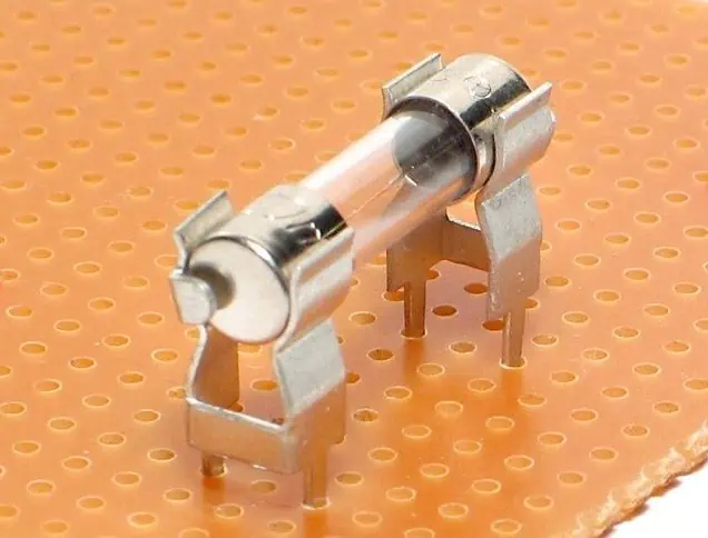
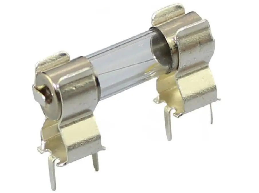
1. Through-Hole Fuse Holders
Through-hole fuse holders are the most popular type of PCB fuse holder for prototyping and low volume production:
Features:
- Two leaded pins for through-hole PCB mounting
- Horizontal or vertical mount options
- Wide fuse size compatibility
- Very easy to manually install/replace fuses
- Low cost
Applications:
- General circuit protection
- Common in electronics prototyping and testing
2. Surface Mount Fuse Holders
Surface mount fuse holders directly mount onto surface mount pads on a PCB:
Features:
- Compact design with low height above PCB
- Available for common fuse sizes like 1206
- Fast automated SMT assembly compatible
- Very stable with good resistance to shocks/vibration
- Often have solder tabs under body for added strength
Applications:
- Cell phones, laptops, and other size constrained consumer electronics
3. Chassis Mount Fuse Holders
Chassis mount fuse holders feature threaded bodies which screw into a cutout hole on device chassis or enclosures:
| Fuse Holder Style | Image | Description |
|---|---|---|
| Open chassis mount | Exposed fuse clips allow fuse accessibility from outside the chassis | |
| Closed chassis mount | Shrouded clip design for applications needing IP rating or safety from live fuse clips |
Features:
- Robust screw mounted mechanical package
- Compatible with wide range of chassis materials and thicknesses
- Easy to replace fuses from outside device
- Protects from accidental user contact with live fuse
- Special versions meet IP67 rating for water proofing
Applications:
- Industrial control boxes and power devices
4. Fuse Clips
Fuse clips provide a spring clamping receptacle to securely grip cartridge type fuses:
Features
- Tight retention force avoids vibration issues
- Wide compatibility with tube and cartridge fuses
- Excellent high current capacity
- Chassis or PCB mountable
Applications:
- Heavy duty power electronics
- Automotive, HVAC and Energy
This covers some of the most popular fuse holder types used with PCBs. There are also more application specific designs like waterproof power fuse holders found in boats and RVs.
Understanding the pros and cons of each will help identify the right solution for your protection needs.
Typical Specifications to Consider When Selecting a Fuse Holder
Choosing the optimal fuse holder involves balancing factors like:
Fuse dimensions – The fuse holder cavity must match your fuse size. Common dimension specs are diameter, length and amp rating.
Mounting style – Through hole, surface mount, chassis or panel mount. Should suit production volume and access needs.
Contact type – Clip, blade, end cap or wire grip options for electrical contact.
Voltage and current ratings – Ensure ratings exceed your application needs with safe margin.
Termination – Solder, screw, quick connect or custom terminations to match equipment interfaces.
Features – Consider IP rating, pass-through, cover interlock or status indicators offered.
To demonstrate, here is a comparison table with key specifications for different sample fuse holder part numbers provided by two manufacturers – Littelfuse and Eaton:
| Specification | Through-Hole Holder | Surface Mount Holder | Chassis Mount Holder |
|---|---|---|---|
| Part Number | Littelfuse: 157742 | Eaton: MF-MSMF020 | Littelfuse: 14xLHD i |
| Fuse Dimensions | 5 x 20mm | 1206 size | 5 x 20mm |
| Mounting | PCB Through-hole | SMD | Panel chassis mount |
| Contact type | Brass clips | Solder tabs | Nickel plated clips |
| Voltage Rating | 560V | 50V | 600 Vac/dc |
| Current Rating | 15A | 2A | 20A |
| Termination | Long wire leads | Tabs under body | 1⁄4-inch male quick connects |
| Features | – | Polarized | Viewing window |
Analyzing key specs like this helps ensure the selected holder is compatible with your fuses, PCB and other interface requirements.
How to Install and Use PCB Fuse Holders
Properly installing and using fuse holders is critical for reliability of your system protection. Here are best practice guidelines for through-hole and surface mount fuse holder installation.
Through-Hole Fuse Holder Installation
Through-hole fuse holder installation involves the following key steps:
- Insert leaded wires – Insert the fuse holder leads into corresponding holes on PCB. Ensure holder aligns properly with fuse access cutout if case used.
- Solder pins – Solder pins to copper PCB pads using standard soldering technique ensuring no shorts or cold joints.
- Inspect solder joints – Carefully inspect that solder joints are complete with good wetting and fillets. Reheat and reapply solder if needed.
- Clean flux residue – Clean flux remaining after soldering using alcohol/acetone and lint-free wipe.
- Insert fuse properly – Align fuse properly before inserting fully into fuse clips with firm pressure. Improper insertion can lead to bad contacts or fuse damage.
- Check for continuity – Use DMM to test continuity across the fuse inside the holder and verify circuit is complete.
Following this reliable installation process avoids contact issues or failed fusing down the line.
Surface Mount Fuse Holder Installation
The installation process for surface mount fuse holders requires the following steps:
- Apply solder paste – Apply precise solder paste volume onto SMD pads on PCBs using solder stencil.
- Position holder – Use pick and place system or tweezers to accurately align holder position over wetted pads.
- Send through reflow oven – Pass board with holders through conveyorized reflow oven heating to form solder joints.
- Inspect solder joints – Inspect under magnifying glass that solder wetting and filleting is sufficient across all holder heel contacts.
- Clean residues – Clear all flux residues left after reflow to avoid electrical leaks or corrosion issues.
- Insert fuse – Carefully and completely slide correct fuse into holder channel.
- Functionally test – Power up populated board and test fuse holder opens circuit properly under simulated overcurrent event.
Again following workmanship standards avoids premature fuse fatigue or failure to trip when needed.
Designing and Laying Out Fuse Holders on PCBs
Several key factors go into successfully integrating fuse holder circuit protection into your PCB design:
Leave Clearance for Fuse Access
- Leave sufficient clearance openings in enclosure so that fuses can slide in/out of the holder cavity easily using fingers or fuse pullers
Place Close to Power Entry
- Position holder as close to power entry point or protected IC to minimize exposed PCB trace length to the fuse. This limits unprotected areas.
Minimize Heat Sinking
- Avoid placing fuse holder immediately adjacent to heat sinks or hot components. Excess heating can impair fuse breaking ability.
Route Traces Appropriately
- Route suitably sized copper traces from the fuse holder to match rated breaker current. Avoid using traces as bottlenecks.
Follow Assembly Restrictions
- Plan housing openings for chassis mount holders accessibility. Account for access needs of panel mount clips.
By appropriately positioning the fuse holder early in the PCB layout process, room can be left for thermal clearance, routing and assembly access.
Here is an example block diagram symbol and layout footprint for incorporating a through-hole fuse holder onto a PCB design:
This demonstrates one technique for cleanly integrating fuse holder protection in the schematic capture and PCB layout process.
Troubleshooting Common Fuse Holder Issues
Some typical fuse holder problems encountered are:
Intermittent or high resistance electrical contacts
- Cause: Loose, corroded or oxidized connection
- Fix: Clean contact surfaces, replace clips, ensure firm insertion pressure
Fuse not blowing properly
- Cause: Excessive heat sinking stealing power from fuse element
- Fix: Relocate fuse holder away from thermal masses
Nuisance tripping
- Cause: Overrated fuse or excessive inrush current
- Fix: Increase fuse rating or use time-delay fuse type
Fuse fatigue or damaged elements
- Cause: Excessive switching cycles or currents near fuse rating
- Fix: Select higher rated fuse or evaluate derated operational conditions
So in summary, many fuse holder issues can be prevented through careful product selection, controlled installation and routine maintenance.
Frequently Asked Questions
What is the difference between a fuse holder and a fuse block?
Fuse blocks usually refer to larger terminal blocks designed for higher power industrial applications. These feature screw terminals to connect external wiring rather than soldered PCB traces. So fuse blocks are often panel mounted DIN rail components for partial power distribution rather than circuit protection inside equipment.
What size wire gauge should be used for fuse holder connections?
As a rule of thumb, the wires connected to a fuse holder should be rated to carry at least 125% of the current capacity of the fuse itself, along with standard voltage and temperature deratings. So for a 15A fuse, 18 AWG or thicker wire would be recommended.
What is the best way to test a fuse holder?
Often issues with fuse holder contacts or fuse element fatigue may not be noticeable from visual inspection alone. The best way to fully validate fuse holder integrity is by electrically testing for expected continuity by applying rated current through panel or environmental conditions and ensuring the fuse successfully opens the circuit. This functional testing exposes unseen weak points.
How are replaceable fuses accessed within sealed chassis mount holders?
Some chassis-mount fuse holders feature IP67 sealing gaskets, transparent windows and hinged covers to enable fuse checking and swapping without fully disassembling equipment. This allows users to replace faulty fuses by simply opening the fuse access door rather than removing the fuse holder entirely when needed.
Can I connect multiple wires into a single fuse holder terminal?
This is generally not recommended, as squeezing multiple conductors under a single fuse holder contact can increase resistance substantially or loosen over time. Best practice is to connect a single wire into each holder contact, potentially using a distribution terminal block first to consolidate multiple input or output wires branching elsewhere.
This covers some common FAQs around properly managing fuse holders in PCB protected circuits. Reach out for any further questions!
Conclusion and Summary
In summary, fuse holders provide indispensable functionality within printed circuit board applications by:
- Safely housing replaceable fuses and interfacing them electrically to a PCB
- Protecting downstream components from catastrophic damage due to overcurrents
- Allowing faulty fuses to be clearly spotted and conveniently swapped out as needed
- Ensuring the fuse remains firmly anchored with reliable connectivity to copper traces
We covered the inner workings, critical specifications like mounting style and current ratings, proper installation methods, layout considerations, troubleshooting tips and FAQs related to effectively utilizing PCB fuse holders for robust circuit protection.
Understanding fuse holder selection and integration best practices empowers engineers to build durable, serviceable and safe electronics ready for the rigors of real world operating conditions. Protect your next product design with the peace of mind offered by intelligent fusing solutions.