In the world of radio frequency (RF) electronics, the choice of connectors plays a crucial role in maintaining signal integrity and ensuring optimal performance. SV Microwave Solderless Compression Connectors have emerged as a game-changing solution for RF printed circuit boards (PCBs), offering numerous advantages over traditional soldered connections. This comprehensive guide will explore the intricacies of working with these innovative connectors, their benefits, installation techniques, and best practices for achieving superior RF performance.
Understanding SV Microwave Solderless Compression Connectors
What Are Solderless Compression Connectors?
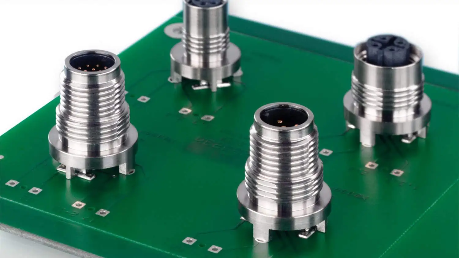
Solderless compression connectors, as the name suggests, are RF connectors that do not require soldering for installation. Instead, they utilize mechanical pressure to establish a secure and reliable electrical connection between the connector and the PCB. SV Microwave, a leading manufacturer in the RF industry, has developed a line of high-performance solderless compression connectors designed specifically for RF applications.
Key Features and Benefits
SV Microwave Solderless Compression Connectors offer several advantages over traditional soldered connectors:
- Quick and Easy Installation: The solderless design allows for faster assembly and reduced production time.
- Improved Reliability: Eliminates the risk of cold solder joints and thermal stress on components.
- Consistent Performance: Mechanical compression ensures uniform contact pressure across all connections.
- Reworkability: Connectors can be easily removed and replaced without damaging the PCB.
- Enhanced RF Performance: Optimized design for superior electrical performance at high frequencies.
- Thermal Management: Reduced heat exposure during installation helps protect sensitive components.
Types of SV Microwave Solderless Compression Connectors
SV Microwave offers a variety of solderless compression connectors to suit different RF applications:
| Connector Type | Frequency Range | Impedance | Common Applications |
|---|---|---|---|
| SMA | DC – 18 GHz | 50 Ohm | General RF, Test & Measurement |
| 2.92mm | DC – 40 GHz | 50 Ohm | High-frequency RF, Millimeter-wave |
| 2.4mm | DC – 50 GHz | 50 Ohm | Microwave, Satellite Communications |
| 1.85mm | DC – 65 GHz | 50 Ohm | Millimeter-wave, 5G |
| 1.0mm | DC – 110 GHz | 50 Ohm | Extremely high-frequency applications |
Designing RF PCBs for Solderless Compression Connectors

PCB Layout Considerations
When designing RF PCBs for use with SV Microwave Solderless Compression Connectors, several factors must be taken into account:
- Footprint Design: Ensure that the PCB footprint matches the specific connector model’s requirements.
- Trace Impedance: Maintain consistent impedance throughout the signal path, including the transition to the connector.
- Ground Plane: Implement a solid ground plane beneath the signal traces to minimize signal loss and interference.
- Clearance: Provide adequate clearance around the connector for proper tool access during installation.
Material Selection
The choice of PCB material is critical for optimal RF performance:
| Material | Dielectric Constant (εr) | Loss Tangent | Suitable Frequency Range |
|---|---|---|---|
| FR-4 | 4.3 – 4.7 | 0.02 – 0.03 | Up to 4 GHz |
| Rogers 4350B | 3.48 | 0.0037 | Up to 10 GHz |
| Rogers 5880 | 2.2 | 0.0009 | Up to 77 GHz |
| PTFE | 2.1 | 0.0002 | Up to 110 GHz |
Select a material that balances performance requirements with cost considerations for your specific application.
Installation Process for SV Microwave Solderless Compression Connectors
Preparation
Before installing the connectors, ensure you have the following:
- Clean work surface
- ESD-safe environment
- Appropriate compression tool
- Connector-specific installation fixtures (if required)
- Torque wrench (for securing the connector body)
- Cleaning supplies (isopropyl alcohol, lint-free cloth)
Step-by-Step Installation Guide
-
Inspect the PCB: Ensure the PCB footprint matches the connector specifications and is free from defects.
-
Clean the PCB: Use isopropyl alcohol and a lint-free cloth to remove any contaminants from the connection area.
-
Align the Connector: Carefully position the connector on the PCB, ensuring proper alignment with the footprint.
-
Apply Compression: Using the appropriate compression tool, apply even pressure to secure the connector to the PCB.
-
Verify Connection: Inspect the connection visually and electrically to ensure proper contact and alignment.
-
Secure the Connector Body: If applicable, use a torque wrench to tighten the connector body to the specified torque value.
-
Final Inspection: Perform a final visual and electrical inspection to confirm the installation’s quality.
Common Installation Pitfalls and How to Avoid Them
- Misalignment: Use alignment fixtures or guides to ensure precise positioning of the connector.
- Over-compression: Follow manufacturer guidelines for compression force to avoid damaging the connector or PCB.
- Contamination: Maintain a clean work environment and handle components with care to prevent contamination.
- Improper Tools: Use only tools specifically designed for SV Microwave Solderless Compression Connectors.
Testing and Verification
Electrical Testing
After installation, perform the following electrical tests to verify proper connection and performance:
- Continuity Test: Ensure electrical continuity between the connector and PCB traces.
- Isolation Test: Verify that there are no short circuits between signal and ground.
- Insertion Loss Measurement: Measure the signal loss across the connector-PCB interface.
- Return Loss / VSWR Measurement: Evaluate the impedance matching quality of the connection.
- Time Domain Reflectometry (TDR): Analyze the connector-PCB transition for impedance discontinuities.
Mechanical Testing
Perform these mechanical tests to ensure the connector’s physical integrity:
- Pull Test: Apply a specified axial force to verify the connector’s mechanical strength.
- Torque Test: For threaded connectors, verify that they can withstand the specified mating torque.
- Vibration Test: Subject the assembly to vibration to ensure the connection remains stable.
Maintaining RF Performance
Best Practices for Optimal Performance
- Proper Grounding: Implement a comprehensive grounding strategy to minimize noise and interference.
- Signal Integrity: Use appropriate PCB design techniques to maintain signal quality, such as controlled impedance traces and minimizing vias.
- Shielding: Incorporate effective shielding measures to protect sensitive RF circuits from external interference.
- Thermal Management: Consider the thermal impact of high-frequency operation and implement appropriate cooling solutions.
Troubleshooting Common Issues
| Issue | Possible Causes | Solutions |
|---|---|---|
| High Insertion Loss | Poor contact, contamination | Re-clean and re-compress the connection |
| Intermittent Connection | Insufficient compression, PCB warpage | Verify compression force, check PCB flatness |
| Frequency Response Deviation | Impedance mismatch, improper grounding | Review PCB layout, improve grounding |
| Mechanical Instability | Over-torquing, improper fixture use | Follow torque specifications, use correct tools |
Advanced Applications and Future Trends
High-Speed Digital Applications
As data rates continue to increase, SV Microwave Solderless Compression Connectors are finding applications in high-speed digital systems:
- Data Centers: High-density, high-bandwidth interconnects
- 5G Infrastructure: Millimeter-wave frequency support for next-generation networks
- Automotive Radar: Precision connectors for advanced driver assistance systems (ADAS)
Emerging Technologies
SV Microwave continues to innovate in the field of solderless compression connectors:
- Higher Frequency Support: Development of connectors for sub-THz and THz applications
- Miniaturization: Smaller form factors for dense PCB layouts and portable devices
- Multi-port Connectors: Integrated solutions for complex RF systems
- Smart Connectors: Incorporation of built-in diagnostics and monitoring capabilities
Conclusion
SV Microwave Solderless Compression Connectors represent a significant advancement in RF PCB technology, offering improved performance, reliability, and ease of assembly. By understanding the design considerations, installation processes, and best practices outlined in this guide, engineers and technicians can leverage these innovative connectors to create high-performance RF systems for a wide range of applications.
As the demand for higher frequency and more compact RF solutions continues to grow, SV Microwave Solderless Compression Connectors are well-positioned to meet the challenges of next-generation wireless technologies and beyond.
Frequently Asked Questions (FAQ)
-
Q: What is the maximum frequency range for SV Microwave Solderless Compression Connectors? A: SV Microwave offers solderless compression connectors that can support frequencies up to 110 GHz, such as their 1.0mm connector series.
-
Q: Are special tools required for installing these connectors? A: Yes, SV Microwave provides specific compression tools and fixtures for proper installation of their solderless compression connectors. Using the correct tools is crucial for achieving optimal performance and reliability.
-
Q: Can SV Microwave Solderless Compression Connectors be reused? A: While these connectors are designed for reworkability, repeated compression and decompression may affect their performance. It’s best to consult the manufacturer’s guidelines for specific reuse recommendations.
-
Q: How do I ensure proper alignment when installing the connectors? A: Use alignment fixtures provided by SV Microwave, carefully follow the PCB footprint guidelines, and visually inspect the alignment before and after compression.
-
Q: Are there any environmental considerations for using these connectors in extreme conditions? A: SV Microwave offers connectors designed for various environmental conditions. Consider factors such as temperature range, humidity, and vibration when selecting the appropriate connector series for your application. Always refer to the product specifications for detailed environmental ratings.