RAYPCB · ENGINEERING GUIDE
PCB Cleaning Methods: Match Residue, Components and Verification
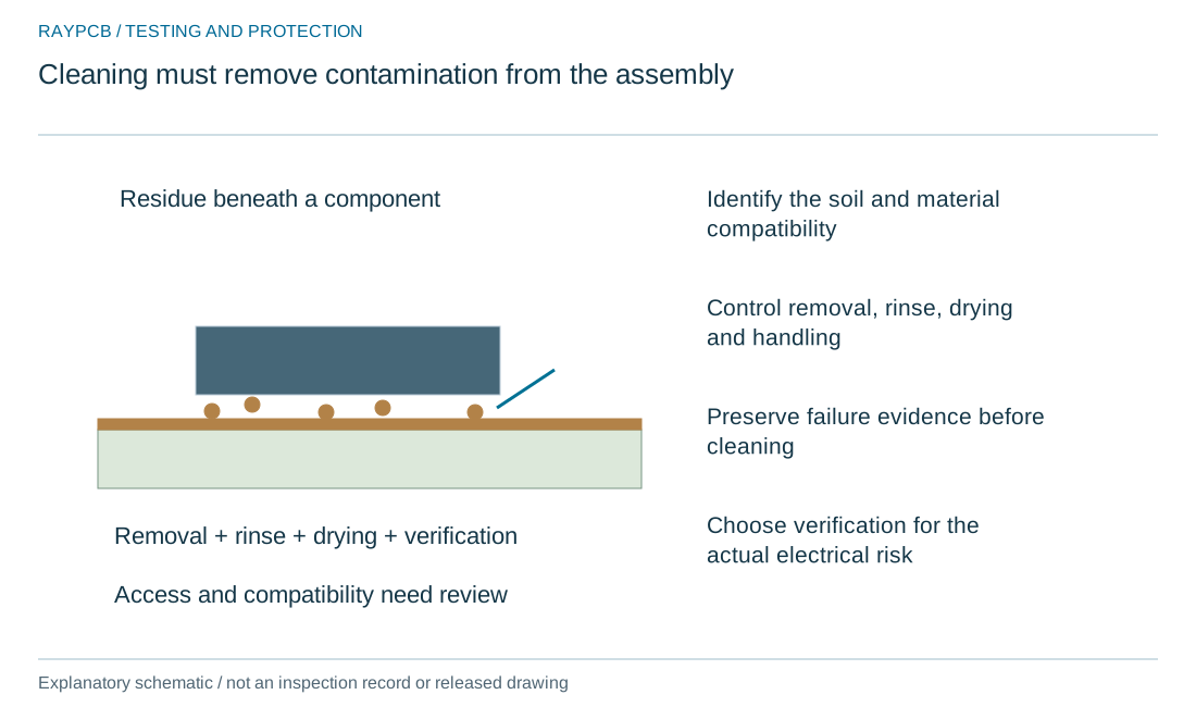
PCB cleaning should remove the relevant contamination without damaging the assembly or leaving a new residue problem. The method depends on the soil, flux system, component construction, surface materials and required cleanliness. A board that looks clean is not necessarily suitable for a sensitive circuit or a subsequent coating process.
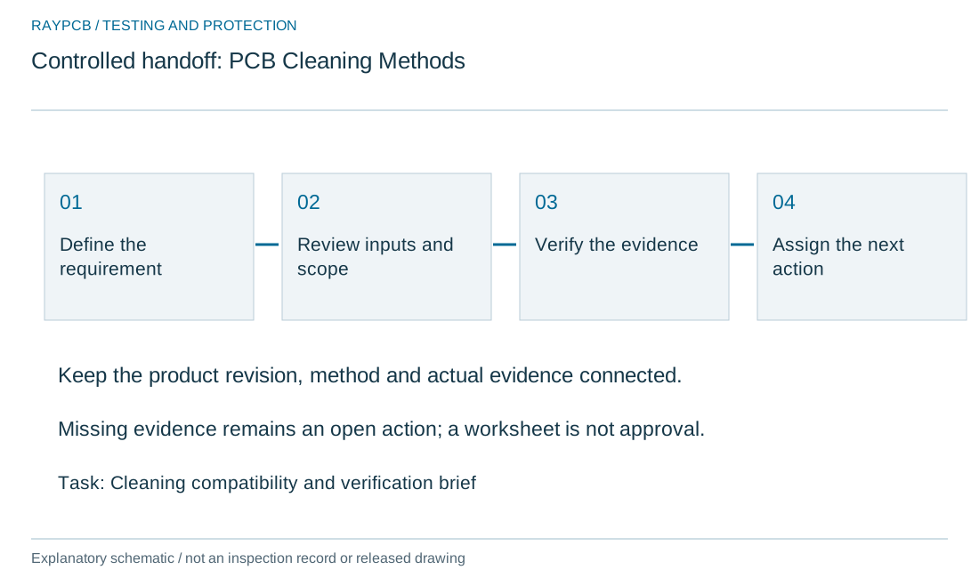
This page compares process decisions rather than prescribing one solvent for every assembly. The online brief records compatibility and verification questions before a cleaning route is selected or changed.
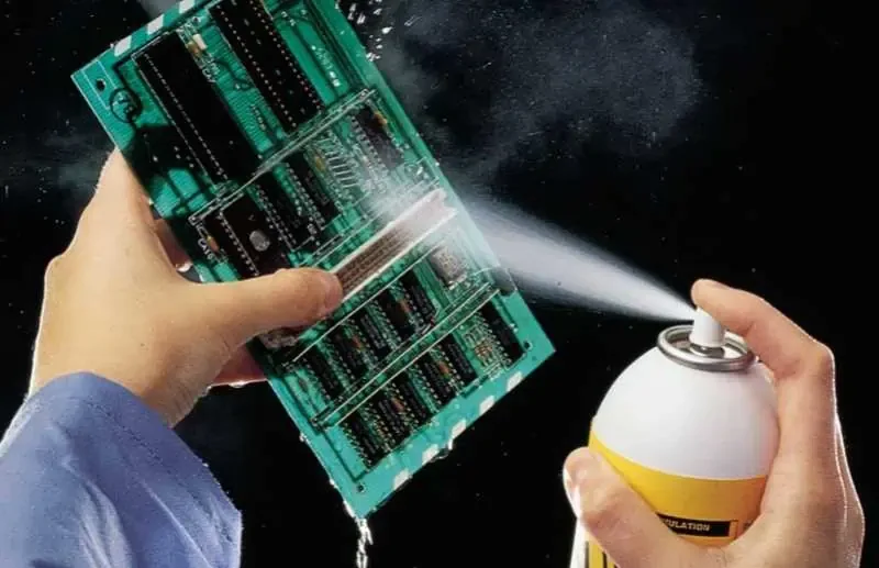
Identify what needs to be removed
Flux residues, handling contamination, particulate matter and service deposits have different characteristics. Record the source and condition of the soil. Distinguish routine production cleaning from cleaning an unknown failed board, where removal may destroy useful evidence.
If the task is failure investigation, preserve the original condition and follow the failure-analysis route before cleaning. The order of operations can determine whether the cause remains discoverable.
Review component and material compatibility
Consider seals, switches, connectors, displays, labels, adhesives and sensitive packages. The assembly's weakest compatibility constraint may control the method. Solvent, water, temperature and mechanical energy can affect different materials in different ways.
Ultrasonic cleaning is not automatically suitable for every populated board. Use component and equipment guidance with a representative validation. Do not infer compatibility from a successful visual result on one sample.
| Review item | What to establish |
|---|---|
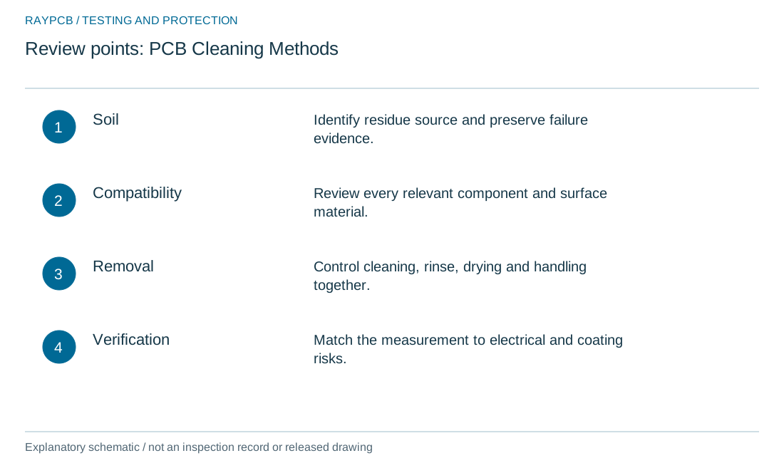
| Soil | Identify residue source and preserve failure evidence. |
| Compatibility | Review every relevant component and surface material. |
| Removal | Control cleaning, rinse, drying and handling together. |
| Verification | Match the measurement to electrical and coating risks. |
Compare the complete cleaning routes
Manual, aqueous, semi-aqueous and solvent-based methods include more than the cleaning medium. Access beneath components, contact time, agitation, rinsing, drying and handling influence the outcome. Follow the actual chemistry and equipment instructions, including workplace controls.
A wipe or brush may redistribute dissolved residue if the route lacks an effective removal stage. The process should transport contamination away from the assembly and establish the required final condition.
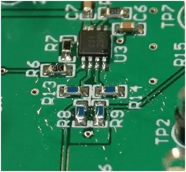
Treat rinse and drying as controlled steps
Residual cleaning chemistry or trapped moisture can undermine the purpose of cleaning. Define how the route reaches inaccessible areas and how the assembly is dried without exceeding material limits. Record conditions relevant to the chosen process.
Do not set a universal drying temperature from a general article. The product, component limitations, chemistry and geometry determine the qualified route. Verify representative difficult locations rather than only exposed flat surfaces.
Cleaning compatibility and verification brief
Cleaning compatibility and verification brief
Use the current inputs and keep the assumptions
Choose the engineering question before entering numbers. Fields begin blank. Load example fills teaching values so you can understand the model; those values are not recommended dimensions, process settings or market prices. The example label remains visible after edits. Reset before preparing a record based entirely on your own project data.
Use the displayed units and keep a reference for each input. Counts must describe the same scope, and measurements must share the declared conditions. A threshold entered by you remains your supplied review condition. The website does not turn it into an IPC limit or an approved product requirement. If the necessary value is unknown, obtain the evidence rather than replacing it with an attractive assumption.
Read the result and its limitations together. An access fraction is not fault coverage, a cost allowance is not a quotation, and a completed evidence checklist is not a safety or quality approval. Negative margins remain visible where the model permits them. They identify a conflict in the entered scenario rather than silently adjusting the result.
Changing an input invalidates the result and disables its download until you run the tool again. The text record contains the inputs, result and limitations. Processing stays in your browser; no CAD files, instruments or certificates are read. No data is automatically transferred to the enquiry form. Download and attach the record manually if useful, or contact RAYPCB directly without completing the tool.
| Input | What to establish before using it |
|---|---|
| Review reference | Use a nonconfidential revision or scope reference. |
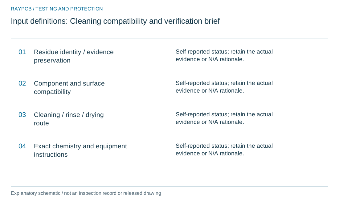
| Residue identity / evidence preservation | Self-reported status; retain the actual evidence or N/A rationale. |
| Component and surface compatibility | Self-reported status; retain the actual evidence or N/A rationale. |
| Cleaning / rinse / drying route | Self-reported status; retain the actual evidence or N/A rationale. |
| Exact chemistry and equipment instructions | Self-reported status; retain the actual evidence or N/A rationale. |
| Relevant cleanliness verification | Self-reported status; retain the actual evidence or N/A rationale. |
| Next action / record reference | Use a nonconfidential reference; this tool does not verify the record. |
Choose verification for the product risk
Visual inspection can identify obvious residues but does not quantify every ionic or organic contaminant. Different analytical or electrical methods answer different questions. Agree the method, sample preparation, limit and decision basis with the responsible team.
For coated assemblies, connect cleanliness verification to conformal coating. Good adhesion alone may not establish every electrical cleanliness requirement, and a bulk measurement may not reveal every localized risk.
Example: a no-clean label is not the entire decision
An illustrative assembly uses a no-clean paste but later requires a coating and contains a high-impedance sensor. The team still needs to evaluate residue compatibility and electrical behavior under the product's environment. The label does not independently approve that combination.
If cleaning is chosen, validate the removal route for the actual residue and geometry. An incomplete or incompatible cleaning step can be worse than a properly qualified retained-residue process.
Request a review with the chemistry and geometry identified
Provide flux or paste identity, component list, assembly drawing, residue concern, downstream processes and cleanliness requirements. State whether the board has been powered, repaired or exposed in service. Include any prohibited materials or methods.
For production, connect the decision to PCB assembly. The tool records open evidence and next actions; it does not approve a solvent or claim that an unseen board is clean.
Questions to resolve before the next build
Is isopropyl alcohol suitable for every residue and assembly? No single cleaning medium should be assumed compatible with every soil, component and downstream process. Use the actual chemistry and component guidance, including removal and drying requirements. A board that looks cleaner may still contain redistributed or inaccessible residue. Verify the relevant final condition rather than treating a familiar solvent name as a qualification.
Should a failed board be cleaned before analysis? Not automatically. Contamination location and residue can be important evidence. Document the original condition and agree the investigation sequence first. If cleaning has already occurred, record the method and materials used so the analyst can interpret what remains and identify evidence that may no longer be available.
Connect surface preparation with the downstream process
Treat protection as a complete assembly process. The relevant chain begins with the product environment and continues through material selection, surface condition, application, cure, inspection and service. A strong result at one step cannot compensate automatically for an unresolved interface or an unsuitable surface at another.
Use a controlled drawing to connect design intent to manufacturing. Mark coated regions, no-coat zones, connectors, sensors, mating faces and future test access. Define how edges and difficult geometry are handled. Include the assembly variant and sequence so that an operator does not have to infer whether a component is fitted before or after protection is applied.
Record the exact materials in contact with the process. Coating product, flux residue, cleaning chemistry, labels, adhesives and component surfaces can all matter. Keep technical and safety documentation available for the selected products. A resin-family name or a general compatibility table is a starting point for review, not proof that the complete combination is suitable.
Use representative trials to resolve uncertain geometry and process behavior. Include difficult access, tall components, shadowed regions and relevant no-coat boundaries. A flat coupon may help characterize some aspects, but it may not reproduce the populated assembly's flow, cure or service-access problems. State what each specimen represents.
Define verification in terms of the actual property. Coverage, thickness, cure, adhesion and electrical behavior are distinct. A fluorescent appearance can help show where a suitable material is present, but it should not be used as an unqualified substitute for every other requirement. Match the observation and method to the decision being made.
Consider the life of the product after shipment. Repairs, connector access, calibration and mechanical maintenance may disturb protection. Establish an approved route for any required removal and restoration, and keep the material identity traceable. If a change makes maintenance impractical, resolve the product tradeoff rather than leaving the service team an undocumented problem.
For purchasing, include preparation, masking, material handling, application, cure, inspection and repair assumptions in the scope. Material price alone rarely describes the complete operation. Ask which trials and records are included, and keep environmental qualification separate from routine production checks. A useful enquiry allows the manufacturing team to review the real assembly and explain the proposed route with its limits.
Standards, source context and limits
Use each reference for its stated scope. Equipment and material documentation applies to the identified product and conditions. A published study describes its own specimens and methods; its settings are not universal production limits. Public standard summaries and revision tables do not replace the controlled normative document.
Agree the applicable standards, revisions, product class where relevant, measurement methods and exceptions before production. Distinguish printed-board requirements, assembly workmanship, laboratory competence and finished-product certification. A method name or photograph does not establish that a supplier holds an accreditation or that a particular test is included in an order.
Archive photographs illustrate relevant boards, equipment or operations from the existing RAYPCB website. They are not evidence of current equipment ownership or results from your project. Original diagrams explain concepts and measurement boundaries; they are not inspection records or released manufacturing drawings. Confirm the actual service and reporting scope in the project review.