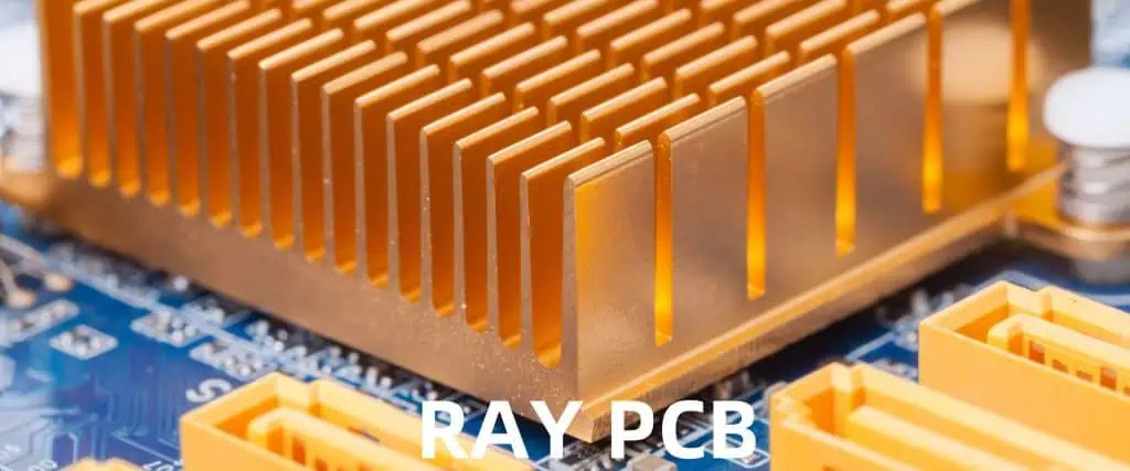
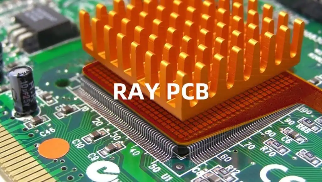
In the world of electronics, thermal management is a critical aspect of design that can significantly impact the performance, reliability, and lifespan of electronic devices. As electronic components become smaller and more powerful, the need for effective heat dissipation becomes increasingly important. One of the most common and effective methods of managing heat in printed circuit boards (PCBs) is through the use of heatsinks. This comprehensive guide will explore the intricacies of PCB heatsink design and selection, providing you with the knowledge and tools to optimize thermal management in your electronic projects.
Understanding Heat Generation in PCBs
Sources of Heat
Heat generation in PCBs primarily comes from active components such as:
- Integrated Circuits (ICs)
- Power transistors
- Voltage regulators
- LEDs (especially high-power variants)
- Resistors (particularly when handling high currents)
The Impact of Excessive Heat
Excessive heat can lead to various issues in electronic devices:
| Issue | Impact |
| Reduced performance | Components may not operate at their full potential |
| Decreased reliability | Higher failure rates and shorter component lifespans |
| Thermal runaway | A self-reinforcing cycle of heat generation and increased current flow |
| Physical damage | Melting, warping, or delamination of PCB materials |
| Signal integrity problems | Increased electrical resistance and signal distortion |
Basics of Heat Transfer

Understanding the principles of heat transfer is crucial for effective heatsink design. The three primary modes of heat transfer are:
1. Conduction
Heat transfer through direct contact between materials. In PCBs, this occurs through copper traces, thermal vias, and the PCB substrate itself.
2. Convection
Heat transfer through the movement of fluids (including air). This is the primary method by which heatsinks dissipate heat into the surrounding environment.
3. Radiation
Heat transfer through electromagnetic waves. While less significant in most PCB applications, it can become more important in high-temperature scenarios or space applications.
Heatsink Fundamentals
What is a Heatsink?
A heatsink is a passive heat exchanger that transfers heat from a hot component to a fluid medium, typically air. Its primary function is to increase the surface area available for heat dissipation, thereby improving cooling efficiency.
Key Heatsink Parameters
| Parameter | Description |
| Thermal resistance | Measured in °C/W, lower values indicate better heat dissipation |
| Surface area | Larger surface areas generally provide better cooling |
| Fin design | Affects air flow and heat dissipation efficiency |
| Material | Determines thermal conductivity and overall performance |
| Weight | Important for portable devices or applications with weight constraints |
Heatsink Materials
The choice of material significantly affects a heatsink’s performance. Common materials include:
Aluminum
- Pros: Lightweight, cost-effective, easy to manufacture
- Cons: Lower thermal conductivity compared to copper
Copper
- Pros: Excellent thermal conductivity
- Cons: Heavy, expensive, can be difficult to machine
Composite Materials
- Examples: Aluminum-graphite, copper-tungsten
- Pros: Can combine desirable properties of multiple materials
- Cons: Often more expensive, may have manufacturing limitations
Heatsink Design Considerations
Surface Area Optimization
Increasing the surface area of a heatsink improves its ability to dissipate heat. This is typically achieved through the use of fins or pins. Consider the following:
- Fin spacing: Balancing between maximizing surface area and allowing sufficient airflow
- Fin height: Taller fins increase surface area but may reduce air velocity
- Fin thickness: Thicker fins conduct heat better but reduce the number of fins possible
Airflow Management
Effective heatsink design takes into account the direction and velocity of airflow:
- Align fins parallel to the primary airflow direction
- Consider using ducting to direct airflow through the heatsink
- In natural convection scenarios, vertical fin orientation is generally more effective
Thermal Interface Materials (TIMs)
TIMs are crucial for ensuring good thermal contact between the heat source and the heatsink:
| TIM Type | Pros | Cons |
| Thermal paste | Excellent contact, fills microscopic gaps | Can dry out over time |
| Thermal pads | Easy to apply, reusable | Generally lower thermal conductivity |
| Phase change materials | Combine benefits of paste and pads | More expensive |
Mounting Pressure
Proper mounting pressure is essential for optimal heat transfer:
- Too little pressure results in poor thermal contact
- Excessive pressure can damage components or the PCB itself
- Consider using springs or torque-limiting screws for consistent pressure
Heatsink Selection Process

Step 1: Determine Thermal Requirements
- Calculate the total power dissipation of the components requiring cooling
- Determine the maximum allowable temperature rise
- Consider any space or weight constraints
Step 2: Choose Heatsink Type
Select from various heatsink types based on your application:
- Stamped heatsinks: Cost-effective for low to medium power applications
- Extruded heatsinks: Versatile, good for medium to high power applications
- Bonded fin heatsinks: High performance, suitable for high power density applications
- Forged heatsinks: Excellent for high-performance computing and telecommunications
Step 3: Evaluate Thermal Performance
Use thermal resistance calculations to determine if a heatsink meets your cooling requirements:
ΔT = P * (Rja - Rjc)Where:
- ΔT = Temperature rise above ambient
- P = Power dissipation
- Rja = Junction-to-ambient thermal resistance
- Rjc = Junction-to-case thermal resistance
Step 4: Consider Manufacturing and Assembly
- Assess the ease of integrating the heatsink into your PCB design
- Evaluate the cost and complexity of the manufacturing process
- Consider any special assembly requirements (e.g., specific mounting hardware)
Advanced Cooling Techniques
Active Cooling
For high-power applications, active cooling methods may be necessary:
- Fans: Increase airflow across the heatsink
- Liquid cooling: Offers superior heat dissipation but adds complexity
- Thermoelectric coolers: Can cool below ambient temperature but require power
Heat Pipes and Vapor Chambers
These advanced heat transfer technologies can significantly improve cooling performance:
- Heat pipes: Use phase change to transfer heat over distances
- Vapor chambers: Provide more uniform heat spreading across larger surfaces
PCB Layout Considerations for Effective Cooling
Component Placement
- Group heat-generating components together when possible
- Place high-power components near board edges for better airflow
- Consider the impact of component height on overall airflow
Thermal Vias
Use thermal vias to improve heat conduction through the PCB:
- Place vias directly under heat-generating components
- Use larger diameter vias for better heat transfer
- Consider filling vias with thermally conductive material
Copper Planes
Utilize copper planes for improved heat spreading:
- Use thicker copper for better thermal conductivity
- Minimize thermal breaks in power and ground planes
- Consider using internal copper planes for heat dissipation
Thermal Simulation and Testing
Computational Fluid Dynamics (CFD)
CFD software can help optimize heatsink design:
- Simulate airflow and heat transfer
- Identify hotspots and areas of poor cooling
- Iterate designs virtually before physical prototyping
Thermal Imaging
Use thermal cameras to visualize heat distribution:
- Identify unexpected hot spots
- Verify the effectiveness of your cooling solution
- Compare actual results with simulation predictions
Temperature Sensors
Incorporate temperature sensors in your PCB design:
- Monitor real-time component temperatures
- Implement thermal throttling or shutdown mechanisms
- Gather data for long-term reliability analysis
Regulatory Considerations

Safety Standards
Ensure your thermal management solution complies with relevant safety standards:
- UL 60950 (Information Technology Equipment)
- IEC 60950 (International Electrotechnical Commission)
- JEDEC JESD51 (Thermal measurement standards)
Environmental Regulations
Consider environmental factors in your heatsink selection:
- RoHS compliance for lead-free solutions
- REACH regulations for chemical substances
- Recyclability and end-of-life considerations
Conclusion
Effective PCB heatsink design and selection are crucial for ensuring the reliability and performance of electronic devices. By understanding the principles of heat transfer, considering various design factors, and utilizing advanced cooling techniques when necessary, engineers can create thermal management solutions that meet the demands of modern electronics. Remember that thermal management is an iterative process, often requiring simulation, testing, and refinement to achieve optimal results.
FAQ
Q1: How do I know if my PCB needs a heatsink?
A1: Consider using a heatsink if your components are operating near or above their maximum rated temperature, or if you notice performance issues related to heat. Calculate the power dissipation of your components and compare it to their thermal specifications. If the ambient temperature plus the temperature rise due to power dissipation exceeds the component’s maximum operating temperature, a heatsink is likely necessary.
Q2: Can I use the PCB itself as a heatsink?
A2: Yes, the PCB can act as a heatsink to some extent. Techniques like using thicker copper layers, thermal vias, and copper planes can help spread heat across the board. However, for components with high power dissipation, a dedicated heatsink is usually more effective.
Q3: How do I choose between natural convection and forced-air cooling?
A3: The choice depends on factors such as power dissipation, available space, noise constraints, and cost. Natural convection is simpler and silent but less effective for high-power applications. Forced-air cooling (using fans) is more effective but adds complexity, potential points of failure, and noise. Generally, if natural convection can’t keep components within their rated temperatures, forced-air cooling should be considered.
Q4: Are there alternatives to traditional metal heatsinks?
A4: Yes, there are several alternatives:
- Graphite sheets: Lightweight and flexible, good for space-constrained applications
- Phase-change materials: Can absorb heat during temperature spikes
- Thermally conductive plastics: Lightweight and moldable, suitable for some low to medium power applications
- Liquid cooling: Highly effective but more complex to implement
Q5: How does altitude affect heatsink performance?
A5: Altitude can significantly impact heatsink performance, especially for systems relying on natural convection or air cooling. As altitude increases, air density decreases, reducing its ability to carry heat away from the heatsink. At high altitudes, you may need to:
- Oversize heatsinks
- Use forced-air cooling instead of natural convection
- Implement more aggressive thermal management strategies Always consider the intended operating environment when designing your thermal management solution.
