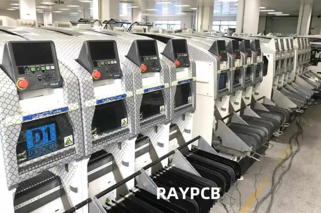
Surface Mount Technology (SMT) has revolutionized electronic manufacturing, enabling the production of smaller, more complex, and highly efficient electronic devices. At the heart of SMT assembly lies the chip mounter, a crucial piece of equipment responsible for accurately placing components onto printed circuit boards (PCBs). Among various types of chip mounters, the multi-head gantry-type chip mounter stands out for its high speed and precision, making it an ideal choice for high-volume production environments.
This article delves into the optimization of SMT assembly processes using multi-head gantry-type chip mounters. We will explore various strategies, techniques, and technologies that can significantly enhance production efficiency, reduce errors, and improve overall product quality.
Understanding Multi-head Gantry-Type Chip Mounters
Basic Principles
Multi-head gantry-type chip mounters are advanced pick-and-place machines designed for high-speed, high-precision component placement in SMT assembly lines. These machines typically feature:
- A gantry system for X-Y axis movement
- Multiple placement heads mounted on the gantry
- A variety of nozzle types for handling different component sizes and shapes
- Advanced vision systems for component recognition and alignment
- Sophisticated software for optimizing placement sequences and machine movements
Advantages of Multi-head Gantry-Type Chip Mounters
| Advantage | Description |
| High Speed | Multiple heads allow simultaneous pick-and-place operations, significantly increasing throughput |
| Flexibility | Can handle a wide range of component types and sizes |
| Precision | Advanced vision systems and motion control ensure high placement accuracy |
| Scalability | Easily adaptable to different production volumes and product types |
| Efficiency | Optimized movements and parallel operations reduce cycle times |
Understanding these fundamental aspects is crucial for implementing effective optimization strategies in SMT assembly processes.
Key Components of a Multi-head Gantry-Type Chip Mounter
To optimize the SMT assembly process, it’s essential to understand the key components of a multi-head gantry-type chip mounter and their roles in the overall system.
1. Gantry System
The gantry system provides the main framework for the chip mounter, enabling precise X-Y axis movement.
- X-axis: Typically the longer axis, allowing movement across the width of the PCB
- Y-axis: Allows movement along the length of the PCB
- Z-axis: Vertical movement for component pickup and placement
2. Placement Heads
Multiple placement heads are mounted on the gantry, each capable of independent movement and component placement.
- Number of Heads: Typically ranges from 2 to 24, depending on the machine model
- Head Types: Can include fixed heads, rotating heads, or a combination
3. Nozzles
Nozzles are responsible for picking up and placing components. Different nozzle types are used for various component sizes and shapes.
- Nozzle Types: Include vacuum nozzles, mechanical grippers, and specialized nozzles for odd-shaped components
- Nozzle Change System: Allows quick and automatic nozzle changes during operation
4. Feeder Systems
Feeders supply components to the placement heads. Various types of feeders are used depending on the component packaging.
- Tape Feeders: For components in tape and reel packaging
- Tray Feeders: For larger or tray-packaged components
- Tube Feeders: For components supplied in tubes
- Bulk Feeders: For small, loose components
5. Vision System
The vision system is crucial for component recognition, alignment, and placement verification.
- Upward-looking Camera: For component pickup inspection and alignment
- Downward-looking Camera: For PCB fiducial recognition and placement verification
- High-speed Image Processing: For real-time component and feature recognition
6. Control System
The control system manages all aspects of the chip mounter’s operation.
- Main Controller: Coordinates all machine functions and optimizes placement sequences
- Motion Controllers: Manage the precise movements of the gantry and placement heads
- User Interface: Allows operators to program and monitor the machine
7. Conveyor System
The conveyor system transports PCBs through the chip mounter.
- Input Buffer: Holds PCBs waiting to enter the placement area
- Placement Area: Where components are placed on the PCB
- Output Buffer: Holds completed PCBs
Component Specifications Table
| Component | Key Specifications | Typical Range |
| Gantry System | Acceleration, Maximum Speed | 1-3 G, 1-2 m/s |
| Placement Heads | Number of Heads, Rotation Speed | 2-24 heads, 2-3 rotations/s |
| Nozzles | Diameter Range, Pickup Force | 0.3-6 mm, 1-10 N |
| Feeders | Tape Width, Pitch | 8-56 mm, 2-72 mm |
| Vision System | Resolution, Processing Speed | 5-20 μm, 50-200 ms/frame |
| Control System | CPU Speed, Memory | 2-4 GHz, 16-64 GB RAM |
| Conveyor System | Width Range, Transport Speed | 50-460 mm, 1-2 m/min |
Understanding these key components and their specifications is crucial for implementing effective optimization strategies in the SMT assembly process using multi-head gantry-type chip mounters.
Optimization Strategies for SMT Assembly

Optimizing the SMT assembly process using multi-head gantry-type chip mounters involves a multifaceted approach that addresses various aspects of the production line. This section outlines key strategies for enhancing efficiency, accuracy, and overall productivity.
1. Component Placement Optimization
Efficient component placement is crucial for maximizing throughput and minimizing cycle times.
- Intelligent Grouping: Group components based on size, type, and placement location
- Dynamic Head Assignment: Optimize the use of multiple heads for parallel operations
- Path Optimization: Minimize head travel distances and optimize placement sequences
2. Feeder Arrangement and Management
Proper feeder setup and management can significantly impact machine efficiency.
- Strategic Feeder Placement: Arrange feeders to minimize pick-up distances
- Component Family Grouping: Group similar components for efficient nozzle utilization
- Just-in-Time Feeder Replenishment: Implement systems for timely feeder refills
3. Vision System Enhancements
Improving vision system performance can lead to faster and more accurate placements.
- Advanced Algorithms: Implement state-of-the-art image processing algorithms
- Multi-camera Integration: Use multiple cameras for simultaneous inspections
- Adaptive Lighting: Optimize lighting conditions for different component types
4. Motion Control and Path Optimization
Enhancing motion control can lead to smoother, faster movements and reduced cycle times.
- Acceleration Profile Optimization: Fine-tune acceleration and deceleration profiles
- Jerk Control: Implement advanced motion control algorithms to reduce vibration
- Predictive Path Planning: Use AI algorithms for optimal path generation
5. Nozzle Selection and Management
Efficient nozzle management is crucial for handling diverse component types.
- Automated Nozzle Selection: Implement intelligent nozzle selection algorithms
- Nozzle Wear Monitoring: Use sensors to detect and predict nozzle wear
- Quick-change Nozzle Systems: Minimize downtime during nozzle changes
6. Production Planning and Scheduling
Effective planning can optimize machine utilization and reduce changeover times.
- Intelligent Job Sequencing: Group similar jobs to minimize setup changes
- Real-time Production Monitoring: Implement systems for live production tracking
- Predictive Maintenance Scheduling: Use data analytics to schedule maintenance
7. Machine Learning and AI Integration
Leveraging advanced algorithms can lead to continuous process improvements.
- Self-optimizing Systems: Implement machine learning for ongoing process refinement
- Predictive Error Detection: Use AI to anticipate and prevent potential errors
- Adaptive Process Control: Dynamically adjust parameters based on real-time data
Optimization Strategy Impact Table
| Strategy | Potential Impact | Implementation Complexity | ROI Timeframe |
| Component Placement Optimization | High | Medium | Short-term |
| Feeder Arrangement and Management | Medium | Low | Short-term |
| Vision System Enhancements | High | High | Medium-term |
| Motion Control and Path Optimization | Medium | High | Medium-term |
| Nozzle Selection and Management | Medium | Medium | Short-term |
| Production Planning and Scheduling | High | Medium | Medium-term |
| Machine Learning and AI Integration | Very High | Very High | Long-term |
By implementing these optimization strategies, manufacturers can significantly enhance the performance of their multi-head gantry-type chip mounters, leading to improved productivity, reduced errors, and increased overall efficiency in the SMT assembly process.
Component Placement Optimization

Component placement optimization is a critical aspect of improving the efficiency of multi-head gantry-type chip mounters in SMT assembly. This section delves into specific techniques and strategies for optimizing the component placement process.
1. Intelligent Component Grouping
Grouping components based on their characteristics and placement requirements can significantly reduce cycle times and improve overall efficiency.
Grouping Criteria:
- Component size and type
- Placement location on the PCB
- Required nozzle type
- Placement force and speed requirements
Benefits of Intelligent Grouping:
- Minimizes nozzle changes
- Reduces head travel distances
- Allows for parallel placements by multiple heads
2. Dynamic Head Assignment
Optimizing the use of multiple placement heads is crucial for maximizing throughput.
Strategies for Dynamic Head Assignment:
- Assign components to heads based on their proximity and grouping
- Balance workload across all available heads
- Dynamically reassign tasks to idle heads to minimize wait times
Head Assignment Optimization Algorithm:
- Analyze component placement map
- Group components based on proximity and type
- Assign groups to heads considering travel distances and nozzle compatibility
- Continuously reassess and adjust assignments during operation
3. Path Optimization
Minimizing head travel distances and optimizing placement sequences can significantly reduce cycle times.
Path Optimization Techniques:
- Implement advanced pathfinding algorithms (e.g., modified Traveling Salesman Problem solutions)
- Consider component height and placement order to avoid collisions
- Optimize Z-axis movements for efficient pick-and-place operations
Path Optimization Metrics:
- Total travel distance
- Number of direction changes
- Z-axis movement efficiency
4. Component-specific Placement Strategies
Tailoring placement strategies to specific component types can improve both speed and accuracy.
| Component Type | Placement Strategy | Benefits |
| Fine-pitch ICs | Slow, precise placement with vision assistance | Improved accuracy, reduced placement errors |
| Large Components | Use of specialized nozzles, adjusted placement force | Better handling, reduced risk of damage |
| Small Passive Components | High-speed placement, gang pick-up | Increased throughput for high-volume components |
| Odd-shaped Components | Custom nozzles, adjusted placement parameters | Improved handling of non-standard parts |
5. Placement Sequence Optimization
Optimizing the order in which components are placed can lead to significant efficiency gains.
Sequence Optimization Considerations:
- Minimize nozzle changes
- Reduce head travel distances
- Consider component dependencies (e.g., taller components placed after shorter ones)
- Balance workload across multiple heads
Sequence Optimization Algorithm:
- Create initial sequence based on component locations
- Apply local optimization techniques (e.g., 2-opt, 3-opt swaps)
- Consider constraints (nozzle changes, component height)
- Iteratively improve sequence using metaheuristic algorithms (e.g., Genetic Algorithms, Simulated Annealing)
6. Real-time Adjustment and Adaptation
Implementing systems for real-time optimization can help adapt to changing conditions during production.
Real-time Optimization Strategies:
- Continuous monitoring of placement accuracy and speed
- Dynamic adjustment of placement parameters based on feedback
- Real-time resequencing to account for unexpected events (e.g., component shortages, feeder issues)
Component Placement Optimization Impact
| Optimization Technique | Potential Throughput Increase | Accuracy Improvement | Implementation Complexity |
| Intelligent Grouping | 10-20% | Moderate | Medium |
| Dynamic Head Assignment | 15-25% | Minimal | High |
| Path Optimization | 5-15% | Minimal | Medium |
| Component-specific Strategies | 5-10% | Significant | Medium |
| Sequence Optimization | 10-20% | Moderate | High |
| Real-time Adjustment | 5-10% | Significant | Very High |
By implementing these component placement optimization techniques, manufacturers can significantly enhance the performance of their multi-head gantry-type chip mounters. The combined effect of these strategies can lead to substantial improvements in throughput, accuracy, and overall efficiency of the SMT assembly process.
Feeder Arrangement and Management
Efficient feeder arrangement and management are crucial for optimizing the performance of multi-head gantry-type chip mounters in SMT assembly. This section explores strategies and techniques for improving feeder setup and operation.
1. Strategic Feeder Placement
Proper placement of feeders can significantly reduce pick-up times and improve overall machine efficiency.
Feeder Placement Strategies:
- Place high-usage components closest to the center of the pickup area
- Group similar component types together
- Consider the PCB layout when arranging feeders
- Minimize head travel distances for frequently used components
Feeder Placement Optimization Algorithm:
- Analyze component usage frequency from production data
- Rank components based on usage and criticality
- Assign optimal feeder slots based on ranking and physical constraints
- Iteratively refine placement to minimize overall travel distance
2. Component Family Grouping
Grouping similar components can lead to more efficient nozzle utilization and reduced setup times.
Grouping Criteria:
- Component size and shape
- Required nozzle type
- Placement force and speed requirements
- Packaging type (tape and reel, tray, tube)
Benefits of Component Family Grouping:
- Minimizes nozzle changes
- Simplifies feeder setup and changeover
- Improves overall pick-and-place efficiency
3. Just-in-Time Feeder Replenishment
Implementing systems for timely feeder refills can minimize machine downtime and maintain continuous operation.
JIT Replenishment Strategies:
- Use smart feeders with component level monitoring
- Implement warning systems for low component levels
- Develop standardized procedures for quick feeder changes
- Train operators in efficient replenishment techniques
JIT Replenishment Workflow:
- Continuous monitoring of component levels
- Automated alerts for low-stock situations
- Preparation of replacement feeders off-line
- Quick-swap procedures for minimal production interruption
4. Intelligent Feeder Management Systems
Advanced feeder management systems can significantly improve setup times and reduce errors.
Key Features of Intelligent Feeder Management:
- RFID or barcode tracking for individual feeders
- Automated feeder