Copper conductors are used to link electronic board components electrically. These boards provide mechanical support to suit electronic gadget components. Before we go into details on how to make a electronic board, let’s first consider what an electronic board means.
What Does an Electronic Board Mean?
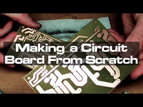
This bare board in which you provide with the layout data as well as which, after we have given this to you, you use it to place your components is known in the industry as printed circuit board.
Utilizing conductive paths, tracks, as well as signal traces that are etched out of copper sheets and laminated to a substrate that is non-conductive, a PCB, is employed to electrically link as well as mechanically support the electronic components.
Whenever the board merely has copper tracks as well as features but no active devices or capacitors or resistors have been fabricated into the board’s actual substrate, then it is referred to as the PWB (printed wiring board or the etched wiring boards.
Though much more accurate but distinguishable from what can be recognized as a genuine pcb, the term PWB has generally lost favor with many people with the line between wiring and circuit gotten more hazy.
Currently, every one of the basic commercially made electronic devices employ printed circuit (wiring) boards, which enable completely automated assembly procedures that weren’t feasible or viable in older tag type processes of circuit assembly.
Important Steps on How to Make a Electronic Board?

PCB Design: The Design and the Output
Although the stage of CAM engineer constitutes the primary step during PCB fabrication, the circuit board design can be described as the preliminary step of the process of etching.
Designers choose the proper power supplies, processors, and other components after analyzing the needs. Make a plan that satisfies all requirements.
The board must, however, be strictly consistent with the layout of the PCB that the designer generated using Circuit board design software. This contract manufacturer must be informed about the software version used for the PCB design that was used to create the circuit, as a designer, since this helps to prevent issues brought on by inconsistencies before the circuit board is made.
Print the finished design onto transfer paper. Ensure the design will fit on the paper’s glossy side.
Circuit Board Design Output
Although alternative databases and formats are accessible as well, data often comes in an Extended Gerber file called RX274x or simply Gerber), which happens to be the most used software.
Gerber files, which all store crucial information enabling synthesis, such as drill patterns, copper trace layer, component symbols, as well as other parameters, may need to be generated using various Gerber file generating processes depending on the Circuit board design program being used.
All the various components of such design are examined to make sure no problems exists after the PCB design layout has been imported in the extended gerber program.
Drawing of the PCB File – PCB Design Film Creation
The following step has to do with printing the PCB when it has been finalized. Normally, this is carried out in a dim space with regulated humidity and temperature. Punch holes within every PCB picture film layer at specific locations to align the various layers. The images for the copper routes were created with the aid of this movie.
Advice: As a Circuit board designer, please remember to inform your manufacturer to perform DFM inspection after generating the Circuit board schematic file.
PCB printing often uses a specialized laser printer termed laser photoplotter; while it’s a laser printer, this differs from a Laserjet printer in many ways. Nevertheless, this shooting method seems to be no longer adequate due to downsizing and technological innovation.
Transfer of the Inner Layer Imaging: Printing of the Inner Layer
Only boards having at least three layers can complete this step. Straightforward, two-layer boards don’t need to be drilled. Steps are added when using multilayer boards.
This preceding step’s film generation was intended to graph its copper journey. The graphics gotten from this film are now ready to be printed on this copper foil. This copper needs to be cleaned first.
Maintaining cleanliness is essential when building PCBs. After being cleaned, this copper-faced laminate gets delivered to the decontaminated area. To prevent opening or shorting of the completed PCB, be sure that there’s no dust settling on the PCB surface.
The photosensitive film coating known as photoresist is applied to its cleaning panel. This copper design is defined by the photoresist being hardened by the printer’s strong UV lamp via a transparent film.
Etching of Copper: Removing any unwanted copper

Etching can be described as the technique of removing surplus copper from the circuit board during PCB fabrication. All that is left on this board after removing the non-circuit copper is the surplus copper. A desirable circuit layout is therefore realized. This base copper, also known as starting copper, gets taken from the circuit board throughout this procedure.
Unwanted copper is eliminated from the board, while required copper is protected by the hardened photoresist, and the unwanted copper is removed from unhardened photoresist. To remove the extra copper, you rinse with acid etchant. Nonetheless, we still want this photoresist layer to completely enclose any residual copper.
Prior to the etching procedure, lithography is used to transfer the circuit image needed by a designer on the PCB. This creates a framework that helps in determining that part of copper that needs to be taken out.
Alignment of the Layers
The layers appear in pairs in order to create a Circuit board “sandwich,” which includes a thin copper foil layer that covers the bottom and top surfaces of the board. A “prepreg” piece would be put between every pair of layer to aid in the bonding process. Prepreg can be described as fiberglass material which has been impregnated using epoxy resin. It melts when laminated because of the pressure and heat involved. The prepreg will glue the layers in place as it cools.
Prepregs, or alternate layers of the fiberglass epoxy-impregnated sheets, are bonded with conductive cores utilizing the hydraulic press and at high pressure and temperature to create multilayer Boards. Prepreg is melted and joined together under heat and pressure. The resulting material, after cooling, will utilize the same process for manufacturing as the double-sided circuit boards.
Drilling of Holes: For the Connection of the Components
The PCB has been drilled with mounting holes, through holes, as well as other holes (which are usually inside the panel stack, with respect to the deepness of the drilled holes). Complex optics offer accurate as well as clean hole walls, which are essential.
The X-ray finder can recognize the proper drilling target point and locate the drilling target’s location. After that, drill pilot holes in the proper places to anchor the stack before drilling a succession of more precise holes.
To maintain a proper drill hole, the technician installs a buffer material beneath its drilling target prior to drilling. Its drill exit is shielded from any unintended ripping by a exit material.
AOI Inspection (For Multilayer PCBs Only)
It is not possible to detect flaws in its inner layers after lamination. Hence, before gluing and laminating, the panels go through an automated optical examination. The machine uses the laser sensor to scan the layer and compare it with the initial Gerber file so as to identify any discrepancies.
The layers must be verified for alignment after they are ready and clean. With the aid of the previously-drilled holes, the outer and inner layers will align. To keep its layers in place, the optical punch punches a pin via the hole. This process of inspection then starts to make sure there aren’t any flaws.
Final stripping and outer layer etch
Photoresist removal

After plating, the photoresist on the panel becomes undesired and must be removed. This is accomplished via a lateral technique that exposes the base copper of the panel to an underlying etching process for elimination while successfully removing the photoresist with a solution of soda ash.
Tin currently shields the optimal copper. Remove any unnecessary copper that is exposed and any copper that is buried beneath the remaining resist layer. In order t o remove the undesired copper during this etch, you utilize the ammonia etchant. Tin also guarantees the current stage’s need for copper.
Conducive regions and links have now been classified legally.
Solder mask
This solder mask is applied using the UV exposure procedure that is akin to photoresist to protect your board throughout assembly. All of the circuit board’s surface will be covered by the solder mask, excluding the functional parts and metal pads.
marks for component reference as well as other circuit board markings will be silkscreened onto the circuit board asides from a solder mask. The board can be baked in the oven to cure the solder mask as well as the ink for screen printing.
The exposed metal surface of the board is going to have a polish. This facilitates soldering operations throughout assembly and protects exposed metal. The surface finish gets exemplified via HASL. Before dipping the board inside the molten solder baths, flux your board to get it ready for solder. High pressure of hot air is used to remove the excess solder out from the holes after this board has been removed from your solder bath and to smooth this solder onto the metal’s surface.
Application of a solder mask
Before applying solder resist to the board’s two sides, epoxy solder ink is put to the panel. This solder mask would let through the Ultraviolet light that the board receives. The piece that was covered is still soft and must be taken off.
The board should then be baked to cure any solder mask.
Because it is easy on the eyes, green was selected as the typical color of solder mask. All processes are manually reviewed before such a machine could inspect the PCB during manufacture and assembly. This overhead lighting that technicians utilize to examine circuit boards is beneficial for human eyes because it does not reflect the greenish solder mask.
Silkscreen
The technique of printing every important information on the surface using profiling or screen printing on the circuit board like name of company, manufacturer ID, debug points, component number, etc. This is very important when repairing and servicing.
Important information gets printed upon that board throughout this process, making it an essential phase. The final curing and coating processes will be applied to the boards after they are finished. This printing of legible identification information, such as 1-pin locators, part numbers, as well as other markings, is known as screen printing. Inkjet printers can be used to print these.
Moreover, it is the most sophisticated method of producing PCBs. In order to identify test points, components, PCBA and PCB part numbers, company logos, warning symbols, manufacturer markings, date codes, manufacturer markings, as well as almost finished boards were printed using easy-to-read lettering.
The final curing and coating stage for the PCB is at last reached.
Flying probe test for electrical testing
The technician would run a functionality test of your board as a last-ditch precaution before inspection. They now perform an automated approach to verify the PCB’s functionality and conformity to the initial design.
Flying probe test, which is an advanced form of the electrical testing, is typically used to examine the electrical functions of every net on such an uncovered circuit board.
Analysis of the production and the V-score
These individual boards could be removed from this panel once the circuit board panel must have undergone electrical testing. A CNC router or machine carries out the procedure to shape as well as resize every board from a panel towards the needed specifications.
According to the total thickness of every panel, several panels could be stacked three or two high to accelerate the procedure and use router bits that are typically between 0.030 and 0.093 in size.
Using different head sizes of milling, the CNC machines may also produce grooves, bevels, and chamfers during the operation.
Final Examination – PCB Quality Assurance
The inspector must perform an extra inspection of every PCB during the process’s last stage. Check the Circuit board visually for adherence to the admission requirements. Utilizing manual and AVI visual inspection Compared to the inspection of the human eye, compares PCBs into Gerber, and yet still needs human verification.
To ensure these items meet the customers’ criteria, all orders would also be thoroughly inspected, including solderability, dimensions, and other factors. Additionally, goods on the board is subjected to a perfect quality audit before even being packed for transportation.
Typical Mistakes in Electronic Board Construction
There are many potential for Circuit board failure concerns to develop due to the complexity of Circuit board design as well as manufacturing processes. A number of the failures are the consequence of design errors, such as inadequate clearances or inaccurate measurements that can impair the end product’s functionality. Everyone else might be the result of manufacturing process issues, such as over-etching or drilling mistakes, which can both be disastrous.
Fortunately, the majority of these mistakes could be avoided having knowledge of the manufacturing procedure, consideration for it, and knowledge of the typical PCB manufacturing problems. Connection problems, component failure, and other concerns related to circuit board can be avoided by adhering to a variety of general design guidelines and considerations.
Plating Voids
Copper-coated holes on the PCB are known as plated through-holes. From one of the sides of your PCB to the second side, electricity can travel through these holes. This PCB board manufacturer drills these holes via the PCB board, completely piercing its base material. Then, using an electroplating procedure, a copper foil layer as well as copper coating is applied to the material’s surface as well as along these holes’ wheels.
Deposition is the procedure used in this step to deposit a thin electroless copper layer to the printed circuit board. Following this, further copper layers will be applied, and the image of the circuit is etched.
Plating voids, which are essentially holes or gaps in the circuit board plating, are usually the consequence of issues with the process of deposition. The plating voids seem to be especially problematic since through-hole plating flaws make it impossible for the electrical current to pass via the hole, leading to a flawed product.
Slivers
When making circuit boards, slivers, which are tiny wedges of solder mask or copper created during the circuit board manufacturing process, can be quite problematic. These fragments, which are frequently created during the process of etching, can happen in any of these ways explained below.
Slivers could first be created by etching away an exceptionally thin, long, characteristic of the solder mask or copper. This sliver occasionally separates before dissolving completely. Inside this chemical solution, these disconnected slivers may float around or even settle on some other board, creating an accidental link.
Cutting a part of the circuit board too deeply or narrowly is another approach to create slivers. Even when they’re intended to remain connected to the circuit board, a material of silver can entirely or partially separate from it if the etched section becomes too small or its etching is too deep, leading to either the peeled-back silver or a floating sliver. Both possibilities could have extremely detrimental effects on the functionality of your circuit board.
Acid Traps
A circuit’s acute angles are frequently referred to as “acid traps.” The acute angles help in trapping acid throughout the process of PCB etching, causing acid to accumulate in the angle’s nook, which is why they are known by this name. Because of the angle, this same acid stays in a corner that is longer than is necessary by design, eating away more material than is planned. Due to this, this acid can weaken a connection, rendering the circuit flawed and leading to subsequent, more severe issues.
The majority of designers were told to stay away from acute angles since they are conscious of the issues they can cause on the circuit board. Nonetheless, errors do occur.
Solder Mask Missing Between the Pads
The copper layer of the PCB is followed by a solder mask layers. To protect its copper traces against contact made with other metals, solder, and conductive bits, the solder mask gets placed on the copper layer’s top. Moreover, it serves as a shield between the copper as well as the environment, preventing corrosion as well as shielding the people handling the PCB from being electrocuted. Components are typically soldered onto the areas of metal known as pads that such solder board has left exposed.
This solder mask between pads may be absent entirely or partially on some printed circuit boards. By exposing excess copper than what is required, this raises the risk of solder bridges unexpectedly forming between pins while assembling.
As a result, the circuit board’s functionality and durability may be adversely impacted by a short as well as lower corrosion protection.
Copper-To-Edge Clearance Not Enough
Copper, which serves like an active constituent of PCBs, is a very conductive metal. But copper also happens to be a somewhat soft metal that is prone to corrosion. The copper gets covered with various materials to stop corrosion and guard against environmental contact.
But, if indeed the copper becomes too near to its edge during the trimming of the PCB, some of the coating may also be removed, revealing that copper layer beneath. Many issues with the board’s functionality may result from this.
Leakage of Chemicals
Another typical problem with PCBs is chemical leakage, which can occur due to the different chemicals utilized when manufacturing PCBs.
The leaking of such chemical residues over time might corrode the metal parts of the circuit boards and lead to short circuits.
Conclusion
By now, you should understand how to make a electronic board. Several electrical parts make up the electronic board. Each part is essential to the operation of the electronic board. PCBs also feature holes where each electrical component needs to be installed. PCBs play a significant role in any electronic device.