A Kelvin connection refers to a four-wire electrical measurement configuration used to determine the precise resistance of a device under test (DUT) with high accuracy. Kelvin connection printed circuit boards (PCBs) integrate this specialized wiring pattern into the PCB traces to enable accurate on-board resistance measurement of components.
In a Kelvin connection, two wires are used to source current through the DUT while a separate two wires sense the resultant voltage drop. This eliminates errors caused by wiring resistance to achieve micro-ohm precision unmatched by traditional two-wire (non-Kelvin) connections.
Why Use Kelvin Connections on PCBs?
There are several benefits to integrating Kelvin connections into a PCB design:
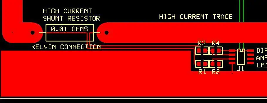
Precision Current Shunt Resistance Measurement
High-power PCBs often incorporate current shunts – low value resistors designed to measure current flowing through a circuit. Kelvin connections on the shunt traces allow micro-ohm resolution that improves current measurement accuracy.
Accurate Sensing of Voltage Drops
Minimizing trace resistance allows small voltage drops across PCB nodes to be sensed with less noise using Kelvin connections. This helps calibrate power regulation circuits.
Analyze PCB Copper Integrity
Measuring PCB trace resistances during quality control verifies design integrity and detects defects like cracks or gaps. Kelvin connections provide repeatable precision trace measurements.
Improved Reliability Testing
Monitoring PCB trace resistance changes using Kelvin connections during temperature or vibration testing correlates small damage before outright failure.
Key Properties of Kelvin Connections
To enable accurate resistance measurement, Kelvin connections exhibit:
1. Electrically Isolated Current and Sense Traces
Separate pairs of traces are used to source current and measure voltage. No current flows through the sense traces.
2. Low Impedance Paths
Thicker, short traces minimize parasitic resistance allowing micro-ohm resolution.
3. Direct Component Terminations
Sense traces connect directly across the resistive component, not indirectly through a node.
4. Optional Shielding
Shielding prevents noise coupling from high current flow into precise sense traces.
##Types of Kelvin Connection Implementation
Several approaches exist to integrate Kelvin connections into PCBs:
Discrete Wired Resistors
Discrete surface mount or through-hole resistors are soldered to dedicated Kelvin termination pads connected by wide traces.
Printed Resistive Elements
Thick-film or etched copper elements patterned directly on the PCB surface act as shunt resistors with Kelvin connections.
Internal Layer Traces
Entire internal copper layers are devoted to low-impedance Kelvin wiring to minimize trace lengths throughout a multilayer PCB stackup.
High Density Kelvin Arrays
Arrays of spring-loaded contact pins allow temporary connections to pads on boards under test for production line automated testing.
| Implementation | Pros | Cons |
|---|---|---|
| Discrete Resistors | Inexpensive, interchangeable | Larger footprint, lower precision, slower measurement |
| Printed Resistors | Compact size, higher precision | Custom fabrication required |
| Internal Layer Traces | Excellent measurement resolution | Complex PCB design, high layer count |
| High Density Arrays | Automated testing, custom grid pitches | Expensive fabrication, fragile pins |
Kelvin Connection Considerations for PCB Design
Several key guidelines should be followed when laying out Kelvin connections in circuit boards:
1. Minimize Trace Lengths
Keep all 4 traces as short and wide as possible to reduce parasitic resistances.
2. Avoid Trace Bends/Shapes
Refrain from trace angles or shapes which increase impedance through the thin circuit board laminate.
3. Use Copper Fills for Shielding
Adding copper fill shapes connected to ground around the traces shields noise sources.
4. Include Test Points
Test points allow temporary connections to the internal PCB Kelvin wiring to facilitate debugging or failure analysis.
Applications and Usage Examples

Kelvin connection PCB implementations enable precise resistance measurement across a variety of applications:
Power Supply Current Monitoring
Shunt resistors with 4-wire Kelvin connections provide temperature stable, high-resolution current sensing for closed-loop supply regulation.
Battery Pack Wired Resistance Measurement
Cell balancing circuits in battery packs leverage Kelvin connections to measure wiring harness resistances influencing voltage accuracy.
Press Fit Connector Contact Resistance Testing
Measuring contact resistance changes in press-fit PCB connectors during thermal cycling qualifies reliability using mayn dedicated Kelvin connection spring pins.
Continuous PCB Trace Integrity Testing
Running high current loads while continuously monitoring copper trace resistances with Kolvin connections over long time periods assesses reliability.
Biomedical Sensor Calibration
On-board Kelvin wiring allows micro-ohm resolution tuning and calibration of delicate instrumentation amplifier circuits used in medical sensors.
Conclusion

Integrating Kelvin connections into printed circuit board designs enables accurate resistance measurement unachievable by traditional two-wire configurations. By isolating current flow and voltage sense pathways both electrically and physically, noise is reduced achieving micro-ohm precision critical for precision current monitoring, voltage drop sensing, and PCB copper integrity validation. With thoughtful layout and shielding, PCBs with Kelvin connections populate a diversity of applications ranging from power electronics to biomedical instruments.
Frequently Asked Questions
How does a Kelvin connection provide more accurate resistance measurement compared to traditional wiring?
Kelvin connections eliminate the measurement uncertainty caused by parasitic resistance in the wires used to source current by providing a separate isolated pair to sense voltage with ultra low-impedance. This avoids measurement error.
What magnitude of resistances can be measured with Kelvin connected PCBs?
Properly designed Kelvin connections allow resistances from milliohms down to microohms to be resolved. This covers measurement of typical current sense elements, PCB traces, and other integrated resistive components.
Does the thickness and length of the traces impact Kelvin connection performance?
Yes, using shorter and thicker copper traces is critical to minimize trace resistances below the micro-ohm devices under test. Long, thin traces degrade resolution through excessive trace resistance and noise pickup.
How many wires does a Kelvin connection require?
Four wires are needed – two distinct connections to each terminal of the resistive device under test. This provides dedicated current flow and voltage sense pathways to avoid measurement errors.
Can Kelvin connections adjust for temperature drifts during resistance measurement?
Yes, by using temperature calibration standards with known resistance drift specifications and similarly constructing the DUT, temperature induced resistance changes can be accurately measured with the Kelvin connection.